Search the Community
Showing results for tags 'viewports'.
-
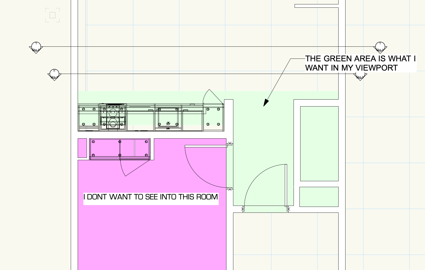
Is there a way to get viewports to wireframe render? I'm trying to model an existing structure. I've got dxf wire models representing scans from my Disto s910. I wish to measure and manipulate bim geometry in reference to those scans. Elevation Level Benchmarks attached to story levels seem to only appear in viewports. So how do I get my viewport to render wirefrane so I can dimension, view, and manipulate everything? Thanks, Rudy Beuc
.thumb.png.76f7513b11aebb5b3ba14fe777edd6a8.png)
.thumb.png.294dbc05a37d74c1a2d8ca3eacbaa45d.png)
.thumb.png.8d4a79411b804a050514b1dd0354e3c9.png)
-
Hi I am trying to render a scene using custom lighting symbols and have the color of the output react to the viewport class color set. I have created some custom fixtures and have a lens in one separate class and the light source in another. When i change the color of the viewport classes to be different than the classes of the main file, only the lens class actually changes color in the render, and not the light sources. The sources are the same color as the main class color, and not the viewport class color. I have the light source in the 3D model set as style solid fill and color to class style. The lens has a texture with color set to "object attribute". Is there a setting somewhere that needs to be changed in order for the viewport class to set the of the light source? Or is there another problem?
-
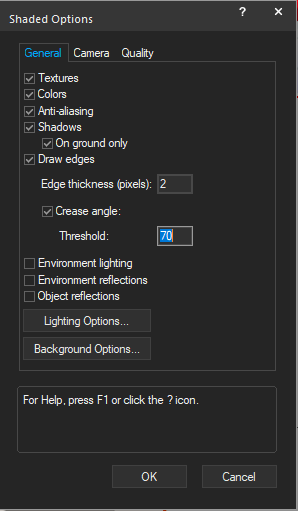
I created a horizontal section viewport to show an interior plan. Hadn't noticed I'd checked Background Render Settings/Shadows /On ground only "on". See image below. Which causes a random grey background in the VP....Removed by checking "off".
-
- 1
-

-
- viewports
- background
- (and 3 more)
-
 Sometimes I have found that my SLVPs do not fully update after I have made a change to either something in the model or the linked camera view. The Foreground Hidden Line is the correct current view, but the Shaded Background render is out of sync. It's like the VGM needs a good kick in the pants. On the SLVP OIP I click 'Update', and it re-renders the view, but the Foreground Hidden Line will be out of sync with the Shaded Background Render view. It is only when I turn off one of the visible Layers in the SLVP, and then click 'Update' does it correctly update the view. slvp update bug.mov
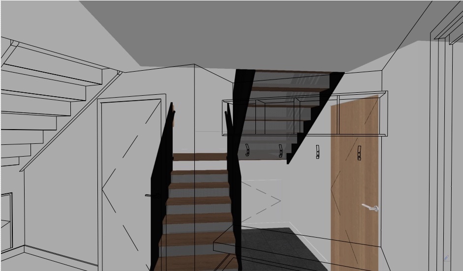
-
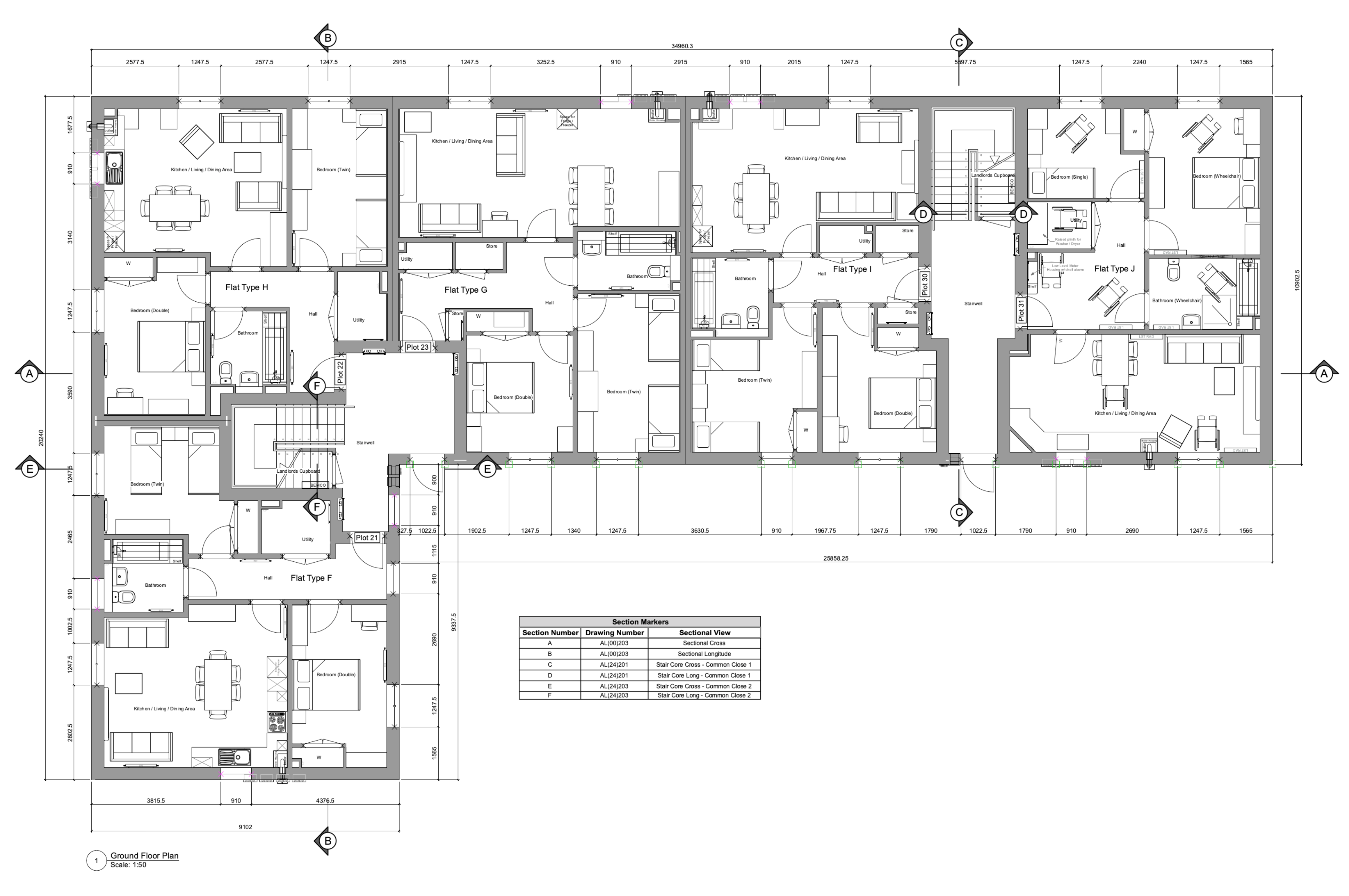
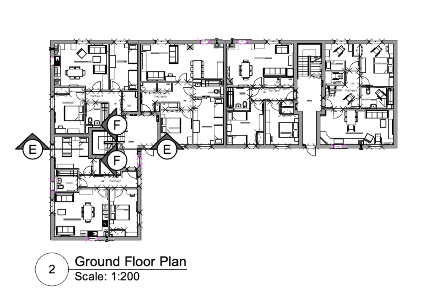
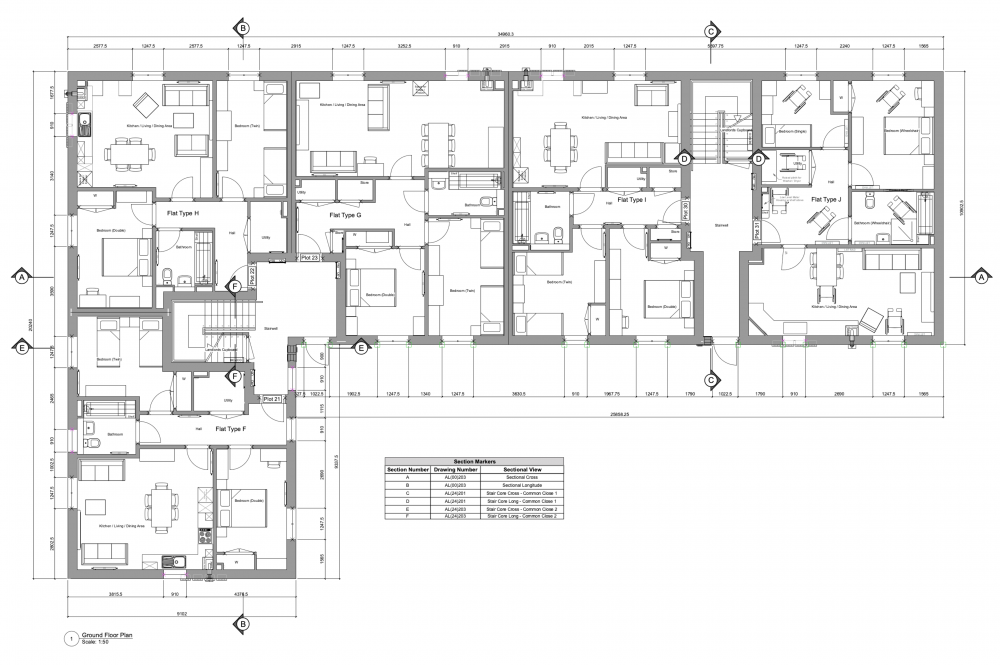
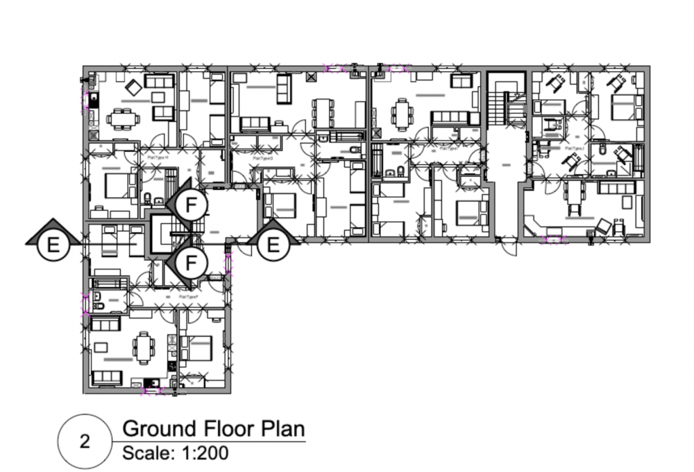
Hoping someone can help with this and we're not missing something obvious. When using coordinated section markers on a plan viewport (1:50) we also show these on the section sheet layer adjacent to the associated section viewport in a contextual plan viewport at a smaller scale (e.g. 1:200) - to allow those reading the drawing to easily identify where a section is taken if reading the section drawing in isolation. Our issue is that the scale of the section markers on the 1:200 scale context viewport appears to be a universal setting across all instances of the marker that are associated with that particular section viewport, meaning they show as either impractically large on the context plan (as shown below) or too small on the main plan if scaled to suit the context plan. Trying to scale markers/symbols etc. in the Advanced Properties for the viewport doesn't appear to affect them and if we change the scale factor for the marker in the annotation layer of one viewport it affects the markers in all other viewports. Is there a way to individually scale these markers for legibility? We are currently working off VW 2022 SP1.1 - While we are aware that SP2.1 is the latest version, there is a known issue with wall hole components of symbols attached to walls that is yet to be fixed.
-
Hello, Is there a way to prevent VP's auto updates after having edited an object directly in the VP ? I want to manually update them in order to save me time. I would appreciate your help.
-
 Good morning everyone, Not sure if this is possible but I thought someone might have discovered a way to do it... My workflow right now for setting up viewports (usually plans) is to control class appearances through a data visualization preset so it's consistent and easy to apply, and then turning on / off class visibilities in the "Classes" options under the Viewport OIP. On every plan viewport, I turn off all the wall component classes so that the walls default to their class appearance. (ie, all new walls are drawn under the WALL-NEW class which is a white fill with a .35 black line). I learned this trick from, I think, a @Wes Gardner video. This is great for simplifying the drawing and making it easier to read but it's a pain for dimensioning when we are dimensioning from structure and not finished faces. It would be wonderful if I could setup a data visualization that would alter both the appearance of the classes AND also the class visibility in the viewport. I like working on the annotations in full colour / detail and it would be grand if with one selection I could set all the visibilities / visual properties for viewport when I'm done or need to switch between the two. I know I can accomplish this with the eyedropper tool but it makes it hard to keep things consistent throughout multiple projects and I have to remember to keep one viewport always set to the "final look" to pull from. Does anyone know if this is possible? Thanks folks!
 -
 To add dimensions in sheet layers, we have to enter into an annotation 'layer' of the individual viewport. Making changes involves a lot of clicking with the mouse. I wish, we could just add the dimensions right there in the sheet without ever leaving the 'top layer'. The dimensions would somehow automatically adjust to the scale of the viewport underneath - and would automatically change when the scale of the viewport is changed and move, when the viewport is moved. And why not?
 -
I know this topic has been floating around in historic posts, but, I'm hoping someone can answer my question below unequivocally (feel a bit silly as I've been using VW for years): Within the Advanced Section Properties of the Cut Plane, can I have each object's respective fill be shown, and add a profile line to the cut elements? Seems I can either alter the settings to specify the profile line, or the fill, but not both. Have I missed something very basic here?
-

Better Viewport Naming and Managment
Tom Klaber posted a question in Wishlist - Feature and Content Requests
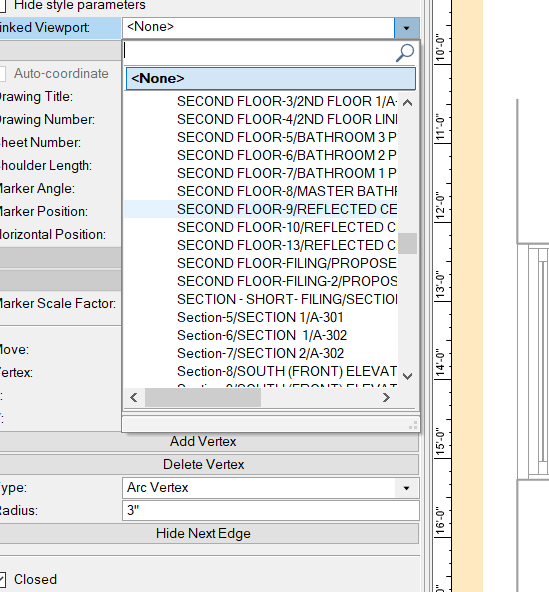
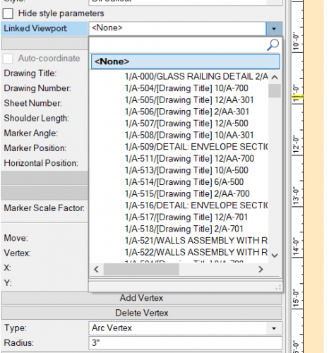
Maybe I am alone - but we are not super disciplined about naming Viewports. Even when we do - when you list the 100s of viewports in a list aphetically - it is still incredibly hard to find what you are looking for. I love the new tags and how VW is becoming better about what I call "dumb-smart coordination." It really is great - but we need a better way for us to link viewports to tags. The list should be organized by the SheetNumber that the viewport is currently on, followed by the Drawing Number currently assigned, followed by the name. Also - the name of the viewport should be able to be set as the Drawing Title - so when you change the title. Viewports seem to be currently named by the number and sheet where they are first created - so after things have moved around a bit - it becomes impossible to find it from the list. So much back and forth to see the name of the viewport, back to the detail tag, ect.
-
After some thought and discussion I decided to try using referenced viewports to create master apartment floor plans. The units are on one file and the building is on another. It is a bit of work to setup but seems good except for one big problem, the units do not show up in 3D. Does anyone have experience using this system and how do I solve the unit 3D issue.
-
 I would like to be able to customise the Default Crop Object in the Viewport and have it show up customised right from when opening the Viewport, rather than having to change it manually again and again. Every time I go into a Viewport to add a Crop Object to my Design Layer by the steps below - it shows a thick green outline: Double Click on a Viewport --> Design Layer --> "ADD REFERENCE CROP OBJECT" Now I know I can place it into a CLASS. But still I would need to add the Crop Object every single time to a Class. Which if you have hundreds of Viewports is rather time consuming.
 -
Hi- Long time 2D drafter using some of my free time to dip my toes in the 3D world. I've modeled a simple wooden desk lamp in Vectorworks and I'm pretty happy with how that went. Now it is time to make the construction drawings and I want to see what the best practice is before I get some bad habits. My lamp is made up of two parts 4X Uprights and 8X Cross Pieces. I'd like to have a sheet for the Upright and a sheet for the Cross Piece. Each piece would need a top, front and right side view. My current solution is to put a copy of each piece on it's own layer and move the viewport crop around as I change the view. Am I missing an easier approach? I'd love to be able to click on the part in the design layer and have a command give me an orthographic projection of it on a sheet layer I can than annotate with dimensions. Any thoughts?
-
Hi all. This viewport is rendered background=unshaded polygon. Has anyone experienced the unwanted diagonal lines, indicated in green, attched? Seem to be associated with a re-shaped wall....any comments welcome. Rendering in opengl solves the problem. (I used unshaded polygon because it renders two extrudes semi-transparent, the ones showing existing gables of this extended house.) 200511 GA Tech 1.pdf
-
Hi, how is it possible in a viewport to show only the data visualisation objects in colour and all other objects/layers in black and white? - without this affecting viewports which require all colours visible. Thanks
-
 When creating viewports the default naming convention is: viewport number / sheet number We would rather it followed this convention: sheet number - viewport number - drawing title Reasons: We'd rather the sheet number was first so that when we're sorting viewports in the nav palette they're grouped by sheet. The forward slash is not a good practice because some systems don't deal well with forward slashes in file names. VE-104110
 -

Move Viewport, not my crop
Anthony Neary posted a question in Wishlist - Feature and Content Requests
I might be splitting hairs on this, but I find it constantly annoying. Alright, let's say I create a cropped viewport on a sheet layer, then I go in to the viewport and move the crop, I would really like Vectorworks to be a bit smarter and keep the viewport crop centered on the sheet layer where it was originally and not make me run after the viewport and move the object back to where it was on the sheet layer. Surely this is feasible? -
Viewport renderings appear 'see through' , as the attached pdf. This happens when exporting to pdf or publishing to pdf. Background renders are set to OpenGL Renderworks. The walls are set to solid in the class settings. Foreground render is set to sketch. I thought it could be file size all be it the pdf file size is only 10MB, so I have tried to reduce the file size by reducing DPI of sheets to 72 or turning off 3 D people and trees and cars but this has not worked. Any suggestions appreciated. 0458-WesthillPavillion-FeasibilityStudies-OPTION-7-test 2.pdf
-
Hi, I'd like to know if it's possible to show instances of sections in horizontal section viewports. I've tried but the VW only shows me viewport which are top/plan and not horizontal section viewports. Thanks in advance.
-
I find using the VW grid line bubble tool very cumbersome and objects often struggle to snap to the lines as well as if the gridlines were drawn just as lines. It is also very cumbersome to adjust, are their advantages to using it? Is there are quick way of transferring gridlines on plan to elevations or section viewports without drawing planes to transfer them to the viewport and then adding them within the annotation layer?
-
It would make navigation of viewports much easier if they can be associated with the page that they are located on. An extra column in the navigation browser that gives the sheet name and number would be helpful.
-
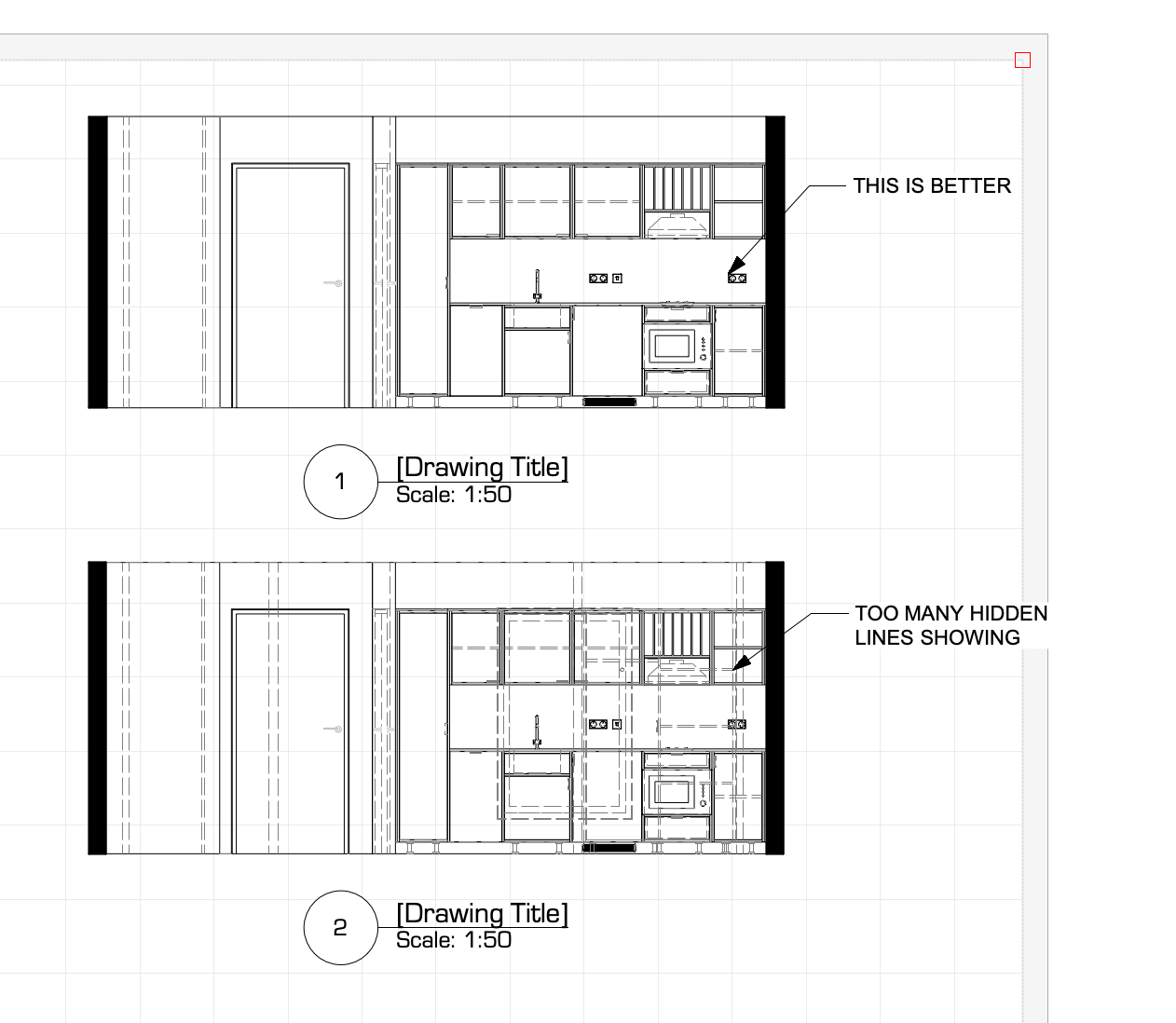
Hello Forum, I'm creating elevation views on my sheet layers from my models. I like to display using 'dashed hidden line' as a lot of my interiors have furniture with shelving inside etc. I know I can turn off classes for certain objects I don't want to display. Is there a way to 'hide' objects from appearing in the background as dashed hidden lines, it makes the elevations look messy and confusing. I guess I'm looking for an efficient way to achieve this, any help much appreciated, cheers (screenshots attached)


-
Is it a known issue that hidden line sketch mode (I'm using Section viewports in this case), produces seriously unstable results? I've run into a few different ways it fails to draw the expected result: The most common issue is that it displays everything in the view, but sketch mode does not appear to be activated. In some cases, the line work initially displays in sketch mode, but then after drawing annotation in the viewport, sketch gets deactivated. To be clear, sketch is still checked off as the desired render option, but the viewport behaves as if it's been turned off. Other times, all of the lines "beyond cut plane" simply don't display at all. Silver lining here is that for whatever reason, this seems to reactivate sketch mode for the cut plane elements and the annotation. There's also cases where the model line work maintains sketch display, but the annotative layer displays without sketch. I've also gotten the reverse situation, where only the annotation was displaying in sketch! It's really all over the map. There does seem to be one way to control this situation (at least it's worked so far). I discovered that by setting the line style of objects beyond cut plane to "use original" in the advanced properties, I can stabilize the sketch render setting, and both model and annotation maintain the correct display. When this is overwritten with a single class, all bets are off. Unfortunately, using the original line style of each modeling object requires a lot more work than being able to quickly set all lines to the same weight. So this is an unfortunate work around to have to accept. Thanks, Matt
-

Editing classes in multiple viewports
hajom posted a question in Wishlist - Feature and Content Requests
It would be nice if one could modify/edit classes in multiple viewports simultaneously. Not just turn them on or off, but also override class attributes like textures etc.. This would speed up work if one is rendering different options for certain components, ie. cladding options, component colours. Also it would be great, if one could override the texture for all aspects of object (wall, roof directions) with one button click. So you don't have to click 5 times to make sure the texture is going to be overridden for all aspects object. Thanks -

Camera Viewport Enhancements
Darrell Henry posted a question in Wishlist - Feature and Content Requests
There are two issues with viewports linked to cameras. The first is the limit of 196mm (35mm equivalent) of zoom (12.45 degree field). This is an artificially low limit that does not allow the previewing of long glass on video cameras (33X or up). The second is that in the OIP it would be great if you could change which camera a viewport is linked to. When you select the viewport on the sheet layer it should say Camera: <name> and you should be able to point it to a different camera.

.png.6d07e0daf50f15118d95ce2d91b2519f.png)
.png.597337341ed2648b77bfa9dc07680d0e.png)
.png.02195f56072e4c11331cc50f1794c9b0.png)