Search the Community
Showing results for tags 'style'.
-
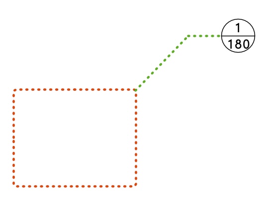
Detail callout markers (DCMs) have three basic parts - The bit I've made red above, which I'll call the "crop box". The line colour, type, thickness and fill of this are controlled per instance, by changing the object's attributes in the attributes panel. If the DCM is given a certain class, then the attributes of this "crop box" can be set to be by class. The shape of this crop box is essentially drawn per instance. - The bit I've made green which VW calls the "leader (and shoulder?)". The attributes of this line can be controlled per instance using the DCM's OIP, or they can be controlled by a DCM style. - The bit I've made black I'll call the "marker" and the layout and appearance of this can be controlled by style What I'd like: 1) The attributes, and basic shape of the "crop box" should be included in the things that can be controlled by style. Why would I want to control the leader & shoulder by style, but not the crop box? It doesn't make sense. At the moment, to get a reasonably consistent appearance for all of these objects I have to do it using a special class. 2) If "rounded rectangle" is to be one of the shapes we can use for the crop box, then the radius of the corner fillets needs to be independent of the scale of the viewport I'm using it on. That is, whatever value I give for the fillet radius needs to produce the same result whether I'm using it on a 1:100 or 1:2 scale sheet layer viewport. I see no reason why it is useful to have it relative to the scale of the viewport. 3) If "rounded rectangle" is to be one of the shapes we can use, and especially if it's not included in the things we can control by style, then there needs to be an easy way of retrospectively changing the radius of those corner fillets. At the moment it's unintuitive and convoluted, and involves changing each vertex individually using the "change vertex mode" of the reshape tool.
- 3 replies
-
- 12
-

-
- detail callout
- style
-
(and 1 more)
Tagged with:
-
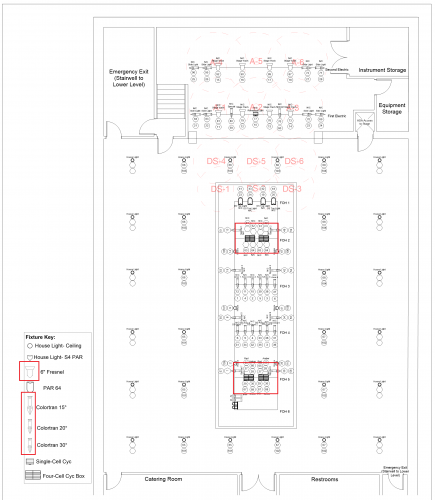
The red squares are where I'm looking and it's alright if there's no actual fix for what I'm going to ask. The ones I've pointed out look significantly different than the rest. Is there a way to change that or is that just how they're going to look in the paperwork? I've tried changing line weights and things and everything is set to just have a black outline, but so far, nothing I've really tried has worked. Thanks in advance!
- 2 replies
-
- formatting
- paperwork
-
(and 1 more)
Tagged with:
-
In VW2019 and now in VW2020, after the new creation of Plant Styles, there is a problem with the way the Plant Tool operates... Upon picking a precisely defined Plant Style to use with the Plant Tool, the tool does not have the ability to place the plants using the Style Definition for Spread, Height, or Spacing. This means that when plants are placed using the tool, they automatically are placed using a custom Spread, Height, or Spacing. This may or may not match the Style Definition, but that is a mere coincidence. The only way to make a plant placement respond to the Style Definition for Spread, Height and Spacing is by first placing plants and then by going into the Advanced Plant Settings, Size Tab, and switching from Custom Spread, Custom Height, and Custom Spacing to Use Plant Style. This is a SEVERE regression and a problem with current workflows. Instead please allow for the ability in the Plant Tool Preferences to utilize the Plant Definitions Spread, Height, and Spacing as a DEFAULT. @Bryan G.@Tony Kostreski @Eric Gilbey, PLA @Vladislav Stanev
-
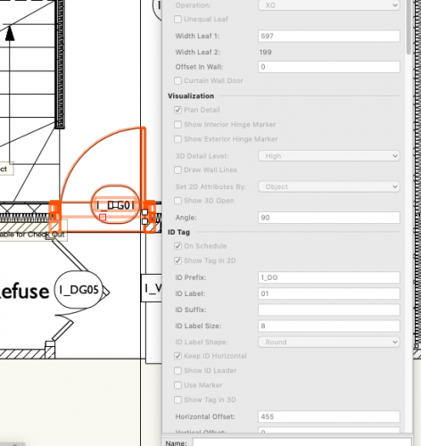
How do I change the ID tag on a door or window, without converting to unstyled? Currently all the instances of a particular style of door have the same ID tag! Not helpful. If I go into the settings for a particular instance, the ID tag options are greyed out....If I convert to unstyled, that defeats the object of having pre-prepared styles that can be edited across the project easily e.g. if Client decides to have a different shaped vision panel in the front doors across a series of houses, or we have particular product data to update the style with later in the project. I'm trying to generate a door schedule too.
-
When deleting a window or door style to have the ability to replace it with another style similar to when you delete a symbol.
-
Tend to just use Arial font but trying to use courier std, but can't get it to display correctly. I'm guessing there's a box I need to tick somewhere or something else...any thoughts appreciated!
-
Is there a way to turn a roof object with a few components into a roof style that can then be applied to other roofs? Yes, yes dumb mistake on my part not making the style first, still seems like there should be an obvious way to do this but its very well hidden.


