Search the Community
Showing results for tags 'site model'.
-
Hi there, I'm having a problem generating a section containing a site model as well as other layers where the building is modelled. Every time I update the section viewport with the site model layer turned on, Vectorworks will take a long time to load, eventually it will freeze and stop responding. The site model was generated from information provided from a surveyor, the model is large and complex and contains a lot of information. Is there a way simplify the model? I have tried to changing the 3D view of the model to triangulated geometries, and reducing contours so it only shows contours every 2m, rather than 250mm. Is there anything else I can do to simplify the model? Or is there anything else I can do to solve this dilemma? Thank you for your advice in advance! J
-

Site Model 2D vs 3D Visual Characteristics
ericjhberg posted a question in Wishlist - Feature and Content Requests
In addition to the several other wishlist items for site models, it would be awesome to have the ability to keep the fill color for the 2d site model to none and still have the ability to have the 3d site model fill solid. Currently, if no fill is assigned to the site model, despite any graphic over-rides set for its 3d properties (i.e. separate classes and properties), then the 3d site model will appear in wireframe, no matter what. The reason for this is because the 2d site model can be used for contours, which often needs to graphically appear above hardscape or flat work, turf, landscape areas etc in order to convey the grading concept...so you set it to no fill and it works beautifully...until you enter 3d and see a wireframe site model. Just another practical use of the tools that should be accomodated for.-
- 1
-

-
- site model
- landscape
- (and 2 more)
-
I want to edit and use some tools for the site model such as cut and fill for the imported site model from elsewhere (ifc format). Can I do this without reconstructing the whole site model all over again from start in Vectorworks? Also, if I exported a Vectorworks site model (ifc format), I cannot edit it again when I import it again to Vectorworks? Is there a way to edit it (and do some cut and fill etc) after the site model was exported?
-
I'd like a Smooth Site option for the Site Model. This would do away with the need to Drape Surface onto an existing site model to get the desired effect. The new Smooth Site would interact predictably all the usual Site Modifiers & settings. Ideally the mesh density would auto-adjust to allow for retention of hard-edged features while reducing the overall vertex count. It would be important to retain existing Texture Mapping of Drape Surfaces.
- 2 replies
-
- 2
-
-
- landmark
- site model
- (and 3 more)
-
 I created my survey site model in one file and a building in a second file. From the Survey file, I attached the building file as a reference file. But Now , how do I translate and rotate the imported layer so that to register in the exact location over the site model? I see the reference layer , but it is placed way out of place.
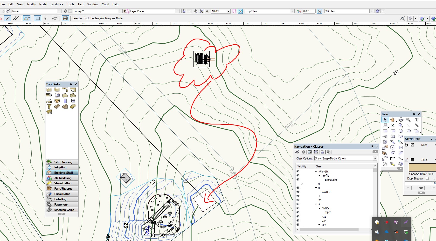
-
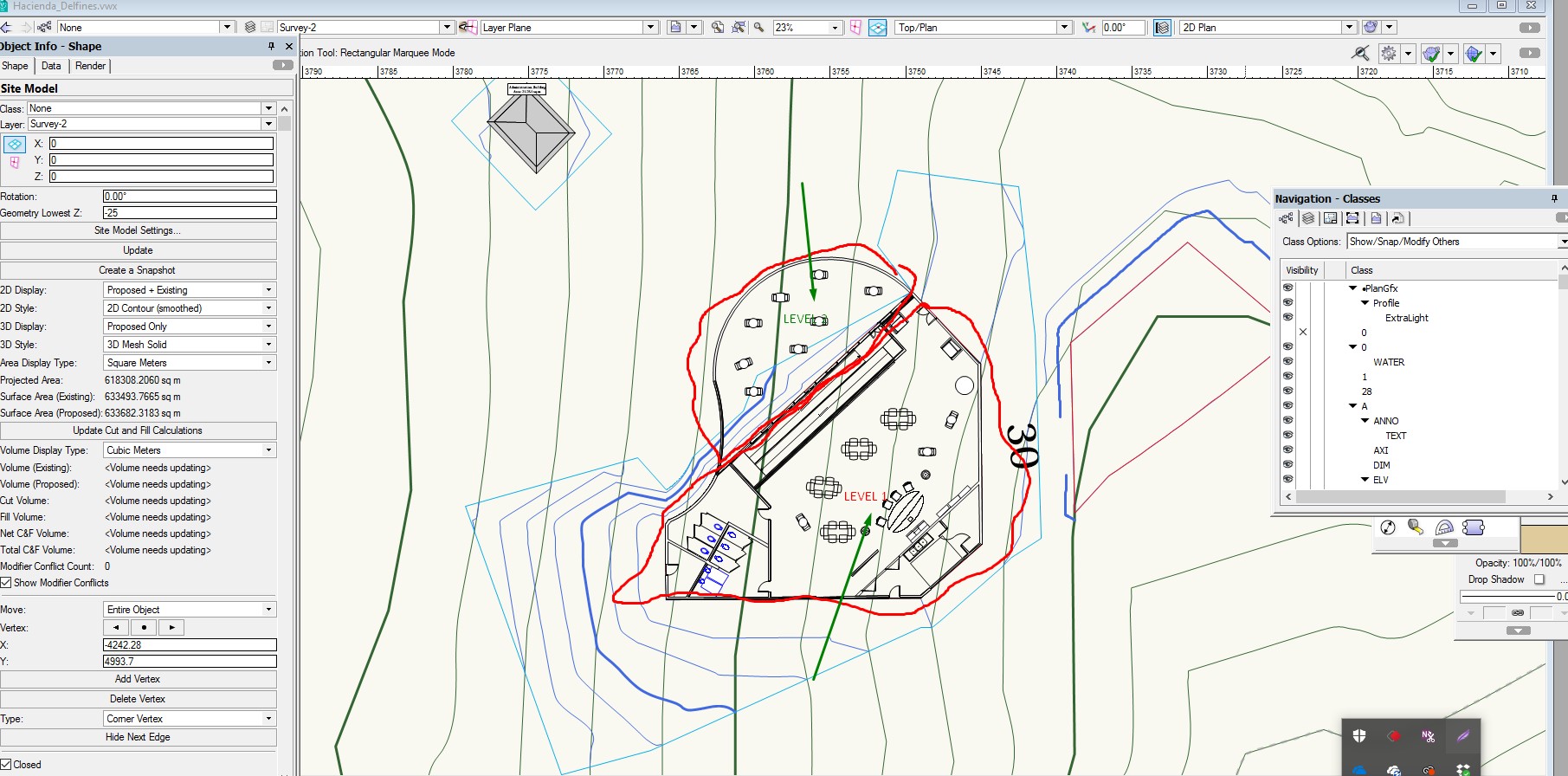
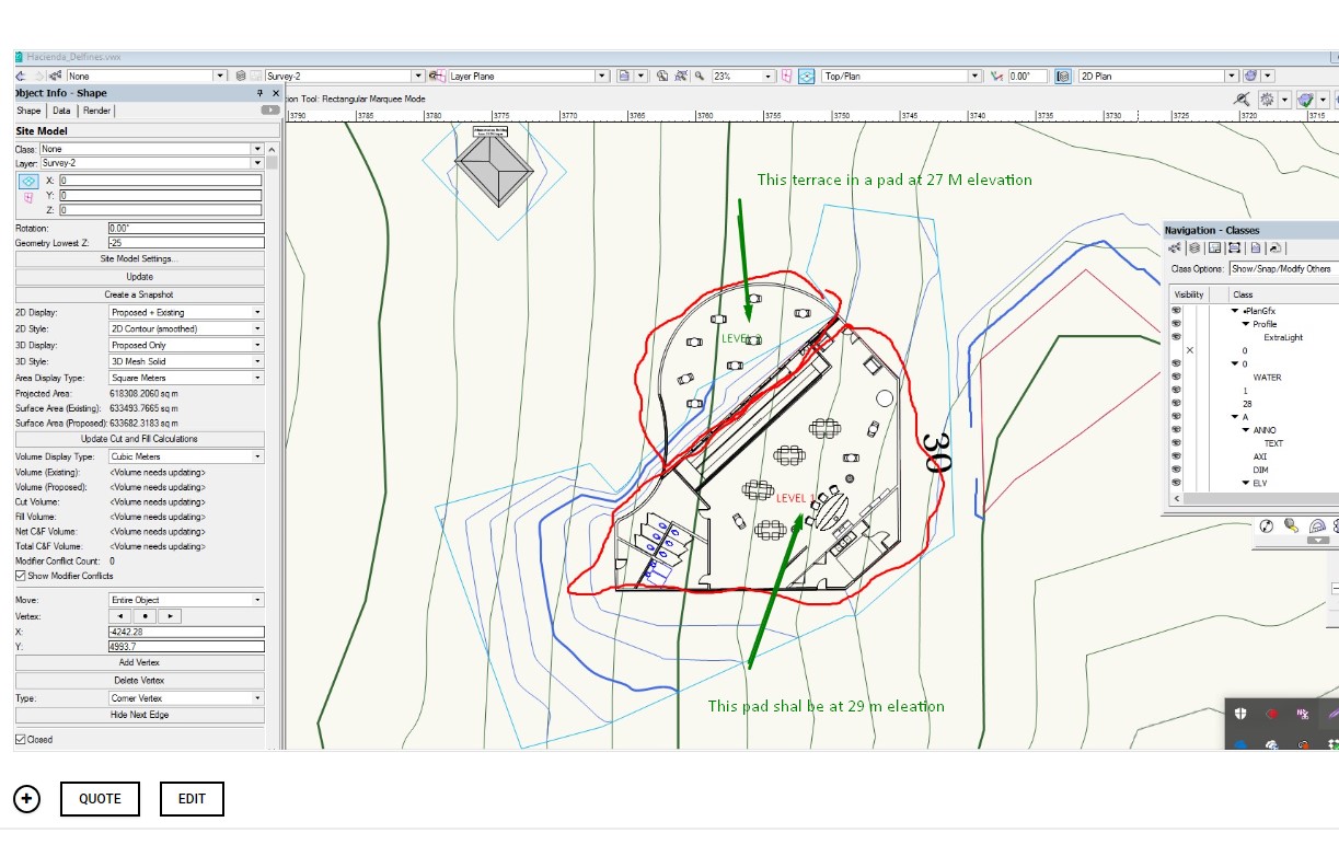
I am working with getting refine skills in Site Modeling. I have a small building resting over a steep hill . I designed one floor building with a terrace at one level and the remaining area steps up into another pad elevation. I have trouble setting the Site Modifier for Pad with retaining wall and normal pad. The problem that I face is that the pad are joined together alone the line that separated both sections of the building returns an error. What technique I need to apply? IS there a better technique to tackle this situation. I sea a lot videos but they don t really take into account Pad modifiers that are aligned one next to the other touching together. Here is a link to the VW drawing... https://www.dropbox.com/s/ro2ke5nzk1dqqh0/Hacienda_Delfines.vwx?dl=0
-

Import IFC from architect workflow please.
nca777 posted a question in Wishlist - Feature and Content Requests
After about two months with landmark I feel I am beginning to run up against the softwares limitations--limitations I strongly feel define the product as a professional landscape architects tool versus one more geared for garden design. We always import IFC files from architects typically working in archicad or revit. I would like to see or hear some detailed workflows on importing IFC models, setting accurate finished floor elevations and doing initial site modeling (including foundations). Most of the architects we work with do an initial pass at grading/site modeling.I need to re-model their site grading somehow so that I can easily edit in VW. A good workflow video (using a sloping site, because sites are never flat) would be great. Any resources out there? -
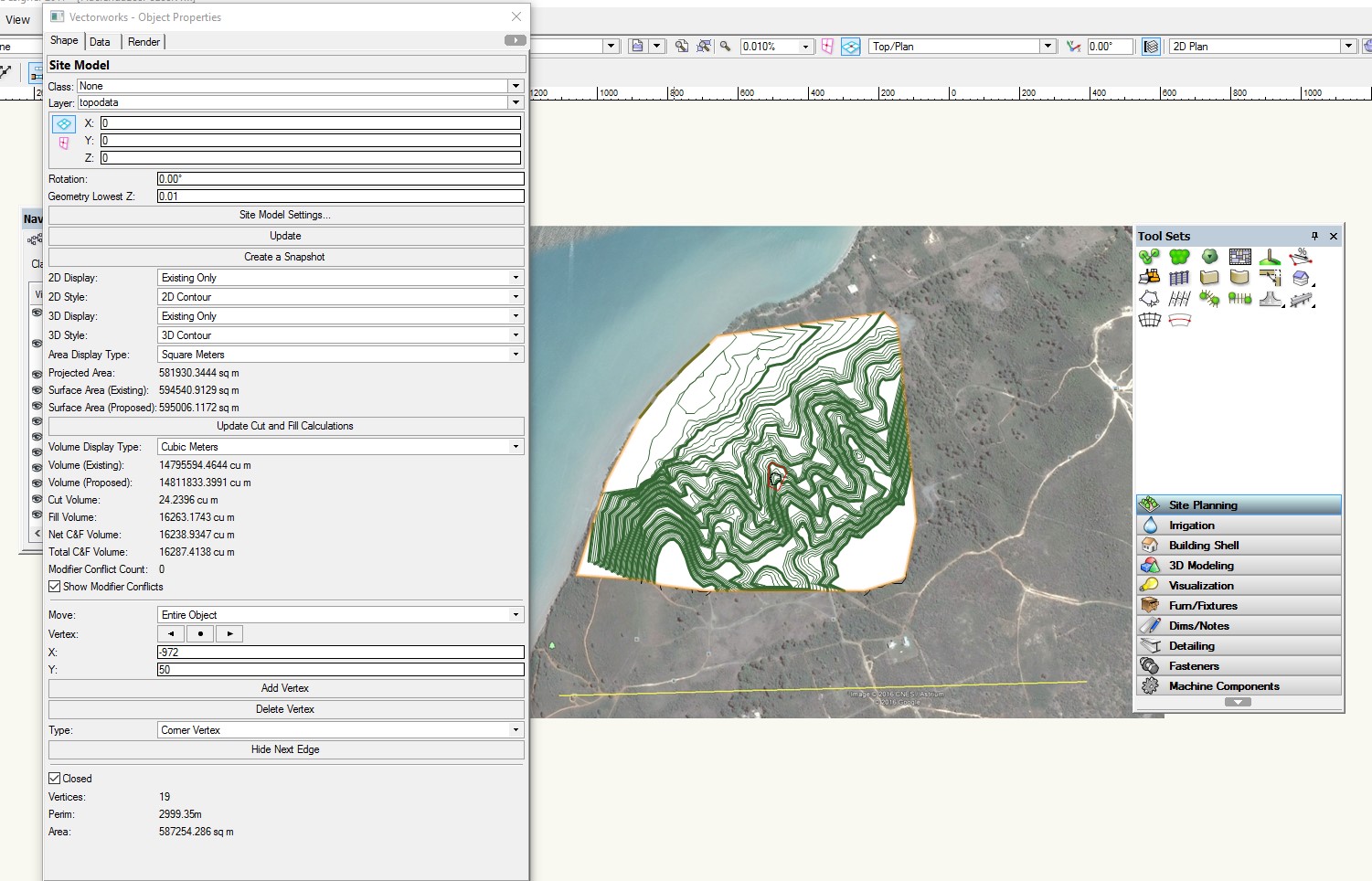
I have no idea what I am doing wrong. I created the Site model follow by a polygon and a site modifier pad. I se the pad height but the contour lines are not modified at all. See That I have a small polygon and a modified pad around the pad. Here is a link to the file https://www.dropbox.com/s/es3twjlnpsus5ct/HaciendaLosPozos.vwx?dl=0 I also notice that the contour lines are all solid. This is contrary to the documentation showing the original to be dashed lines.

-
I have a text file with latitude, longitude and elevation coordinates separated by commas. I'd like to create a site model from this by converting the information into 3d loci or stakes After selecting AEC > Survey Input > Import Survey File, I tried to selecting various options but the elevations of the 3d loci all end up on top of one another, that is the lat. and long. coordinates aren't recognized. What am i doing wrong?
-
Wouldn't it be great if we could layout streets/ driveways/ roads with vertical curve alignments? My wish, aside from world peace, would be to have the ability to create 3D polys that use all the geometry of vertical curves that you would use in road alignments. I've included description from a college course on the subject and a spreadsheet from Michigan DOT that will run the calculation. I use to do these by hand when I first started as a designer in a landscape architecture firm. The built result is a smooth and beautiful transition that avoids abrubt grade changes. GEOMETRIC DESIGN of CURVES.pdf MDOT-Vertical_Curve_Calcs_120887_7.xls
-
This is an update to earlier workaround for site model contours which are flattened or clipped or bridged. I hope this gets fixed in the software. Or others have a better fix. The workaround is rather cumbersome. 7 min video on Vimeo: -B
-

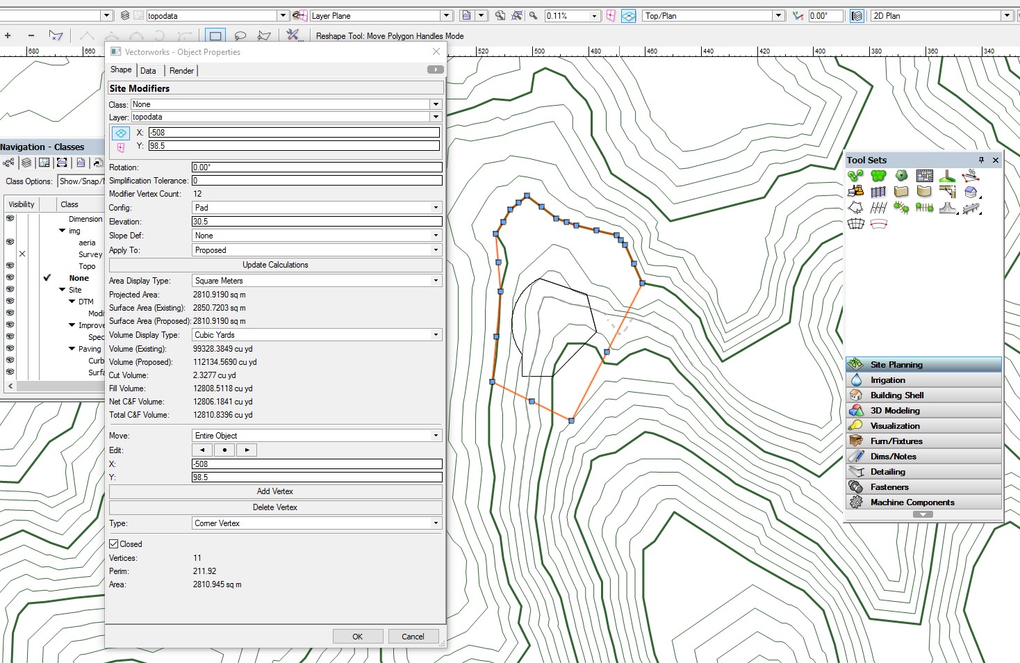
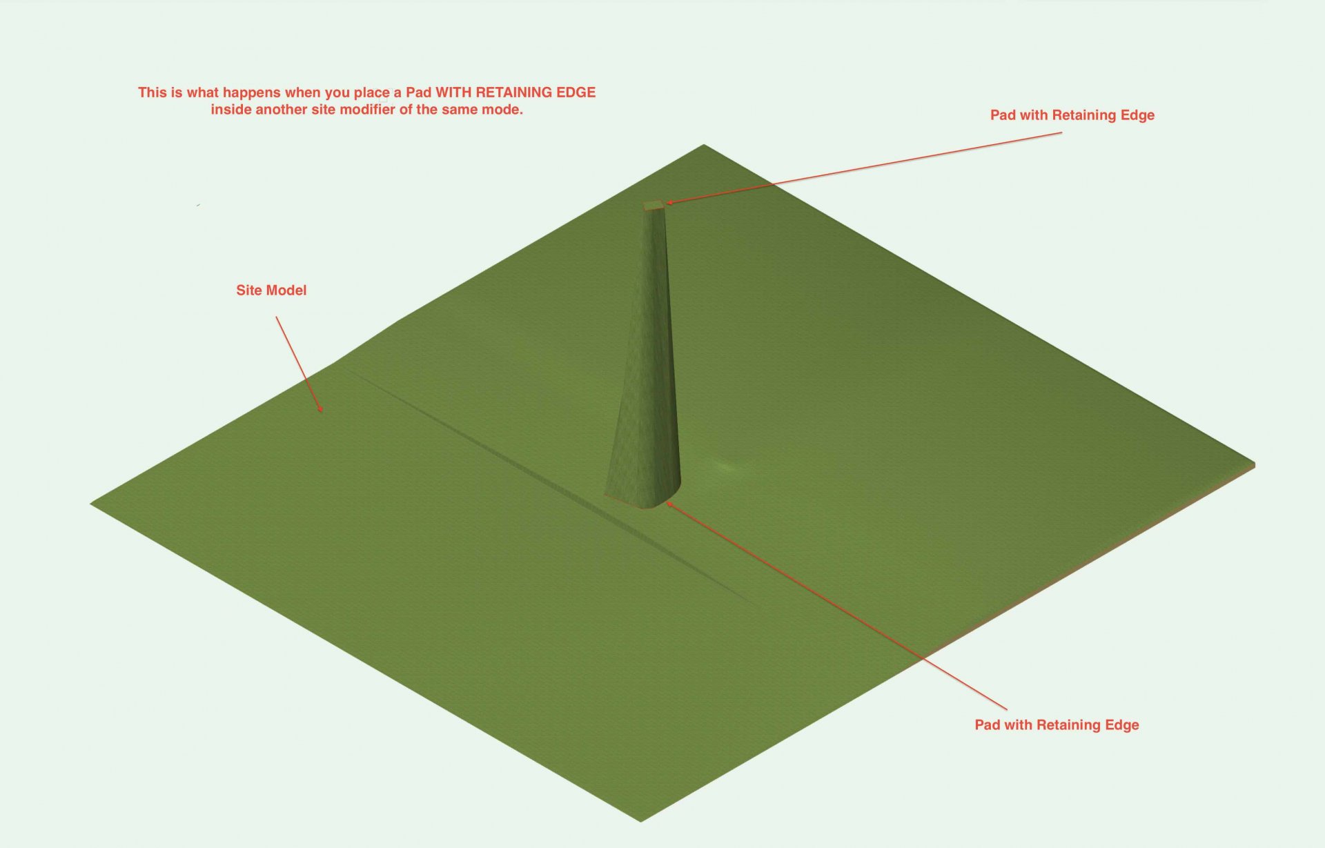
Site Modifiers - Two Pads with Retaining one inside the other
martinfdc posted a question in Troubleshooting
Hi, I'm having trouble getting a Pad with Retaining Edge to Work inside another Pad with Retaining Edge. I attach two screenshots. One is of a Pad with Retaining Edge inside another Pad With Retaining Edge and the other one is the way I believe the combination of the last two mentioned should work (the second screenshot is made though by a Pad with Retaining Edge containing a Pad with a Grade Limits) Am I doing something wrong by placing a Pad with Retaining Edge inside another site modifier of the same mode?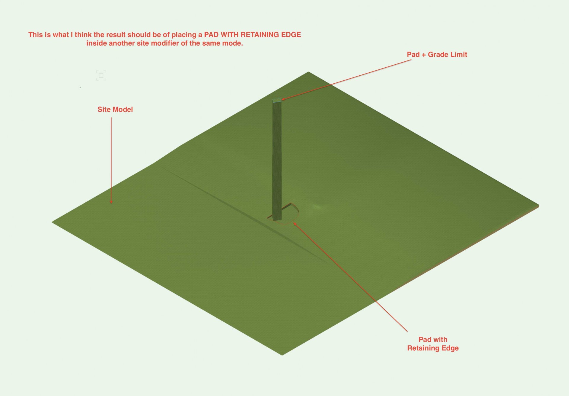
-
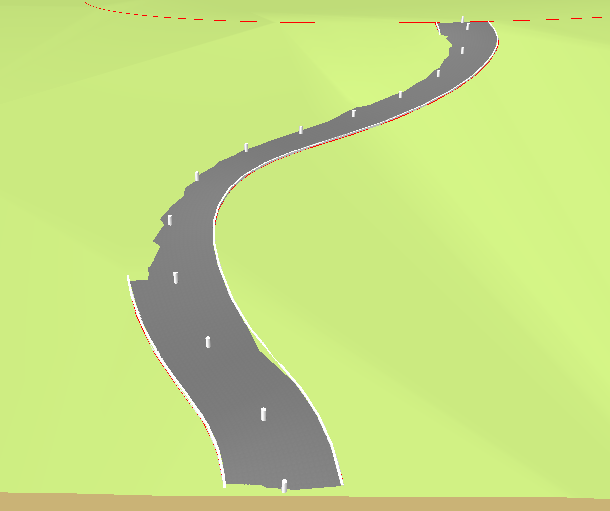
I searched the forum for an answer but to no avail. I'm using the NURBs Roadway tool on a site model with pad and grade limits selected but the site model does not conform to the curve of the road as if the pad and grade limits were not working. Can anyone tell me why?
-
Stake Objects - Prefix or Suffix
ericjhberg posted a question in Wishlist - Feature and Content Requests
This is a fairly simple request. Can a field be added to stake objects that would allow for the addition of a prefix or suffix. This would allow for more precise graphical communication of spot elevation types (i.e. FS, TW, TS, FL, etc.)? We ideally need this information to use stake objects as annotative tools for grading plans. -
We often work directly with civil engineers who are stuck in Autodesks Civil3D world. I know that the suite of tools they use to model terrain, roads, and sites isn't too far off from Vectorworks site models and site modifiers. Everytime we try to collaborate with Civil3D users, we have to dumb the data down to a base .dwg and in doing so we lose a lot of what Civil3D calls AeCc objects. These have a lot of information included that is useful, including the basic graphic attributes and operability. It would be awesome if the import commands for .dwgs or whatever file type is best can better aide the interchange between the two programs! And for that matter, the interchange should work both ways. I should be able to send files with objects that a Civil3D user can easily use and manipulate!