Search the Community
Showing results for tags 'site design'.
-
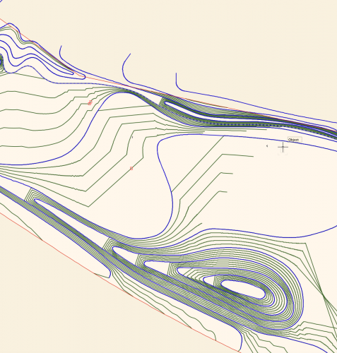
I'm wondering if I'm missing something in terms of the control we have over site modelling in Vectorworks. I've attached a screengrab of a site model I have created. Blue lines are the 3D polyline contours I have drawn and set to 0.5m height intervals, the green lines are the contour lines generated by the site model calculation by Vectorworks, using my blue lines as input data. I have two big issues with this output, namely: I want the model to EVENLY interpolate between the contour lines - for example on the hill to the bottom of the screen grab, I want the mounding to extend evenly to the left, I don't want flat platforms between each level. I want the contours to actually follow the curves I have drawn, and not truncate my contours in large angular lines!! (As seen in the middle of the screengrab.) Is there anything I can do, aside from draw contours at really tight intervals to reduce the visibility of the problem? Is this just how the site modelling algorithm works? I understand the need for a mathematical algorithm, but this results in a fundamentally incorrect site model I can't really use for anything in terms of BIM or production information, as it isn't giving me smooth grades. I'm sure I could fudge it for visualisation purposes, but I need an accurate technical model I can issue in IFC form to provide information for collaboration and also construction. I've turned on mesh smoothing in document properties, which makes the rendered model appear slightly less angular, and also turned on contour smoothing display, but I need an accurate model in terms of BIM compliance and I'm not sure I have this control outwith doing an excessive amount of contour drawing. Is Vectorworks the wrong software for this, or am I missing something? Any ideas or advice would be much appreciated. Lisa
- 21 replies
-
- site design
- site model
-
(and 3 more)
Tagged with:
-
Is it possible to generate a set height contour for a proposed model? For example, I have built a proposed site model. I don't know the footprint of the lake on the on my model in plan, but I do I know the water level on site is 29.150. So, if I could generate a poly line at this height around the model, i.e. a contour line, I would be able to see the footprint of what will essentially be the lake and calculate area / volume etc?
- 26 replies
-
- site design
- model
-
(and 3 more)
Tagged with:
-
Hello, I noticed a problem with the plants tool and the use of VectorWorks internal databases. Indeed, in my process I want to assign personal data to plant occurrences (for example zones, phases or other data). It works quite well overall (sometimes the data disappears for no reason, you have to be careful to have regular backups). You can easily replace a plant with another style of plant, and the custom data is well preserved. But I have a data loss problem when I want to use the group / ungroup the plants function. As much for the grouping of plants having different data fields, I can understand that VectorWorks cannot concatenate the data of the plants (it cannot know what is priority). But for the grouping of plants with the same personalized data, it would be interesting to be able to keep the identical fields filled in. And for the ungrouping of groups of plants, it would be good for the symbols resulting from a group with personalized data to find them once separated. So I don't know if this could be a bug or a feature request (wishlist), so I'm posting my message in this section. Thank you for your comments and suggestions if you have already had this scenario and found a solution. Best regards. Edgar
-
- site design
- plant tool
-
(and 1 more)
Tagged with:
-
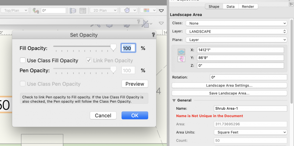
For years, I've been wishing that you could assign different opacities to fill and pen style in a Landscape Area. You can do this with most other objects, but not a landscape area. It would make life a lot simpler as I like drafting with a more transparent fill, while having the pen set to 100%. Basically, I just want to be able to uncheck the "Link Pen Opacity" box in the "Set Opacity" palette.
- 3 replies
-
- 7
-

-
- site design
- landmark
-
(and 3 more)
Tagged with:
-

Send Objects to Surface...works sometimes, but not always
ericjhberg posted a question in Troubleshooting
We often work with site models to visualize projects and there has always been an issue with sending items to the surface. Sometimes it works and other times, no matter what I try, it doesn't Curious if anyone has determined best practices for this or experienced the same issue and have a work around?- 16 replies
-
- site model
- surface
-
(and 4 more)
Tagged with:
-
Hello Marionette aficionados... I would absolutely love a tool for drafting all Site related surfaces/areas including Existing, Demolition and New conditions. Basically it would take a polygon and turn it into something similar to a space object, but with a lot fewer functions. full disclosure: I do not know marionette Preface... Site Plans seem simple, but to fully coordinate all the information that gets put on the Site Plan is pretty intense. Our building department makes us fill out very detailed worksheets. They want to know the area of everything. Getting this info correct is the sort of thing that slows you down to a crawl when you're getting ready for submittals. Description of Tool... One of the biggest benefits of this tool, would be that you could make all of your site surfaces on a single class, let's say "A-SITE-AREA", and allow a lot of graphic changes and record keeping to be bundled into the tool (similar to a space object). But it doesn't need to be nearly as complex as a space object. Space objects are a bit heavy and clunky, and I think drawing a siteplan using spaces would create an undesirable workflow. The OIP for this marionette would need to control the following parameters: "Surface Type": This list would be pretty long, and would cover all of the site classes we currently use when drafting a site plan. It needs to satisfy the basic Architectural, Landscape and Civil design elements. You would still need all these classes in the document, it's just that you wouldn't have to constantly be switching to different site classes as you drafted. Instead, the tool would allow you to link each surface category to a specific class, so that the pen and fill properties belonging to each category could still be independently controlled by separate classes. It would be like how door and window component graphics work. You can link each one to its own component class, or you could choose the object class to keep things simple. "Existing", "Demolition" or "New" ("New" would be the default): Including this function means that each surface category would potentially need 3 separate options for class assignment, one for Existing, one for Demolition, and one for New. Having this single feature hardwired into the tool would save a ton of drafting work. It would also make Site Data Tabulations a lot easier. "Pedestrian" or "Vehicular" (for hardscape surfaces): This wouldn't effect class assignments, but would be needed for Site Data worksheets. Yes, we're asked to provide this information in some jurisdictions. "Permeable" or "Impervious": This also wouldn't effect class assignments, but would be needed for Site Data worksheets. Turn Line Work On/Off: Turn Fill On/Off: Duplicate Line Work: An important feature would be the ability to push a button and get the polygon line work redrawn, removing it from the marionette object, and put onto the appropriate class associated with the surface element it represents. You would want to be able to select multiple surface objects all at once, and then run this command, putting the resultant line work into a group, so it could be easily selected and moved to a different layer. Duplicate Fill: The same goes for the fill Add Label Display Name/Title Display Area Is all of this achievable with marionette? Thanks! Matt Regarding Landmark... I know that Landmark has a Hardscape and Landscape tool that is similar to what I've outlined. If I had Landmark, I'd probably be using these tools. I recently posted to the Site Design section about this to see if I was overlooking something in my version (see link directly below). But there's nothing in Fundamentals or Architecture that does any of this for us. So now I'm turning to all you marionette aficionados... I'm hoping we can make something even better using your skills!
-
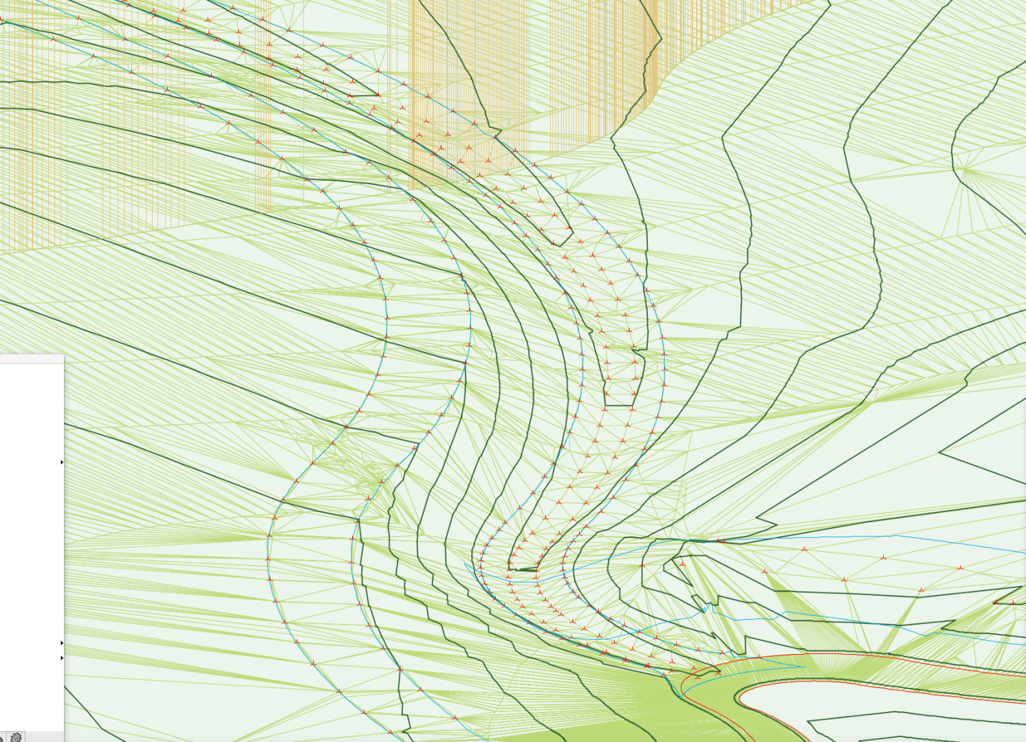
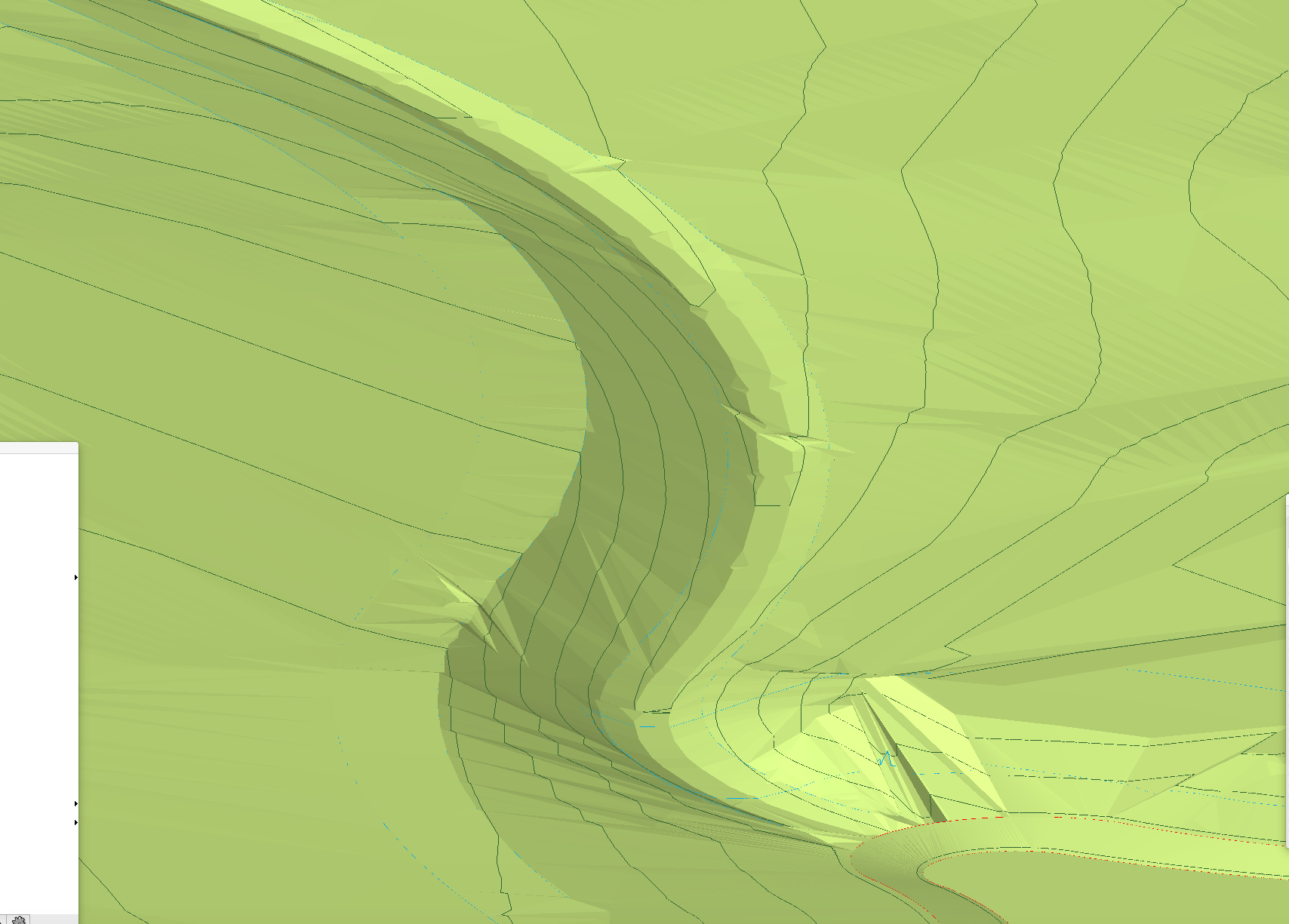
Is there an easy way to smooth my site model without losing too much accuracy? I have little jaggy bits showing in my OpenGL render everywhere between my stake points, as per images! Affecting some contours too.
- 6 replies
-
- site design
- site model
-
(and 5 more)
Tagged with:
-
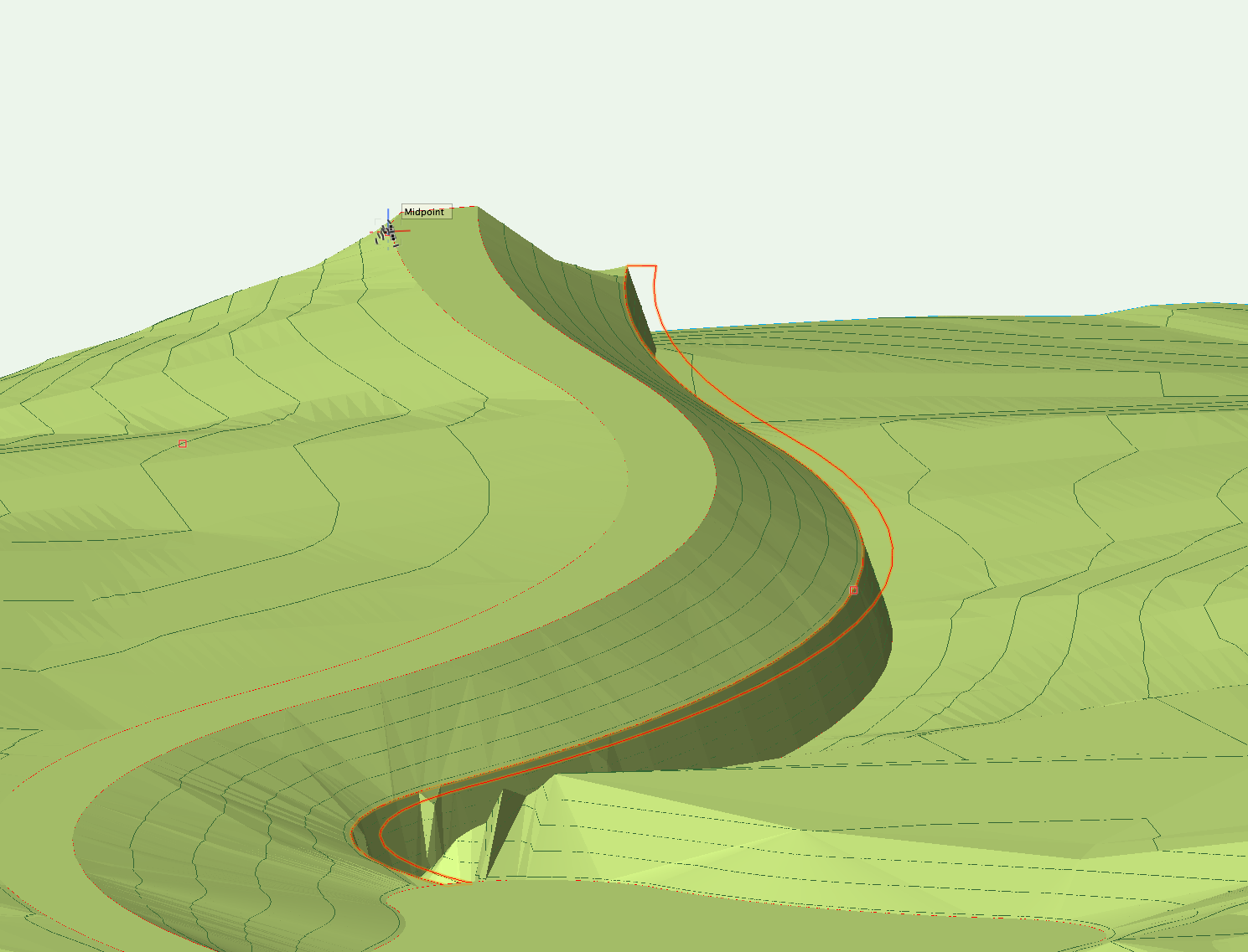
I have created a pad from a closed 3d polygon, which varies in height along a curve on my model. When I update my site model, one edge of the pad acts as I expect it to - the road ramps down to meet the edge of the pad. However, I then expect the inside of the pad to form ground level, and for the site levels on the other side of the pad to meet the edge of the pad - which doesn't' happen? Instead, I get a cliff edge.... can anyone help me with what I'm missing?
- 1 reply
-
- site design
- site modifier
-
(and 3 more)
Tagged with:
-
Hi there, I have an existing site model generated from contours and 3d loci. I want to reprofile this site, so the proposed model will tie at the edges to the existing, but have varying different levels throughout. I thought I could do this quite easily by adding a series of stake objects with proposed level information across my existing model and apply to proposed only, but all the stake objects tie immediately to the nearest point of the existing model's source data, rather than tying to each other or even grading gently into the existing? So now I have lots of spikes across my proposed model instead of a smoothed re-profiled site?! Is there an easy solution to this / am I missing something?

