Jump to content

Search the Community

Showing results for tags 'shell'.

  • Search By Tags

    Type tags separated by commas.
  • Search By Author

Content Type


Forums

  • Announcements
    • Announcements
    • News You Need
    • Job Board
  • Feedback
    • Roadmap
    • Wishlist - Feature and Content Requests
    • Known Issues
    • Wishes Granted / Issues Resolved
    • Forum Feedback
  • General
    • Troubleshooting
    • General Discussion
    • Architecture
    • Site Design
    • Entertainment
    • Previsualization
    • Braceworks
    • ConnectCAD
    • Energos
    • Rendering
    • Workflows
    • Buying and Selling Vectorworks Licenses
    • Hardware
  • Customization
    • AI Visualizer
    • Marionette
    • Vectorscript
    • Python Scripting
    • SDK
    • 3rd Party Services, Products and Events
    • Data Tags
  • Solids Modeling and 3D Printing
    • Subdivision
    • Solids Modeling
    • 3D Printing
  • Vectorworks in Action
  • Archive
    • Resource Sharing
    • Machine Design

Calendars

  • In-Person Training - North America
  • In-Person Training - UK
  • Coffee Breaks
  • Essentials Seminars
  • Webinars
  • Community Groups

Categories

  • Knowledgebase
    • Tech Bulletins
    • Troubleshooting
    • Workflows
    • How To
    • FAQs

Categories

  • Marionette - Objects
  • Marionette - Networks
  • Marionette - Nodes
  • Marionette - Menu Commands

Product Groups

There are no results to display.


Find results in...

Find results that contain...


Date Created

  • Start

    End


Last Updated

  • Start

    End


Filter by number of...

Joined

  • Start

    End


Group


Occupation


Homepage


Hobbies


Location


Skype

Found 4 results

  1. Hi all, I’m trying to recreate the stepped curved form shown in the attached image (see below) except to form a smooth surface closer to the filled and sanded 3D print in the image - I’m hoping to avoid having to manually fill and sand all my 3D solid prints by hand as it’s time consuming, and hopefully avoidable. It’s a series of parallel curved contours that gradually rise in height — a bit like a topographic model and it’s actually part of a skateboard mould if anyone wonders what it is… I’m using Vectorworks Architect 2016, and I’m wondering what the most efficient way would be to create this kind of shape. I tried using: Multiple Extrude, but it only works with 2D planar shapes and doesn’t follow a curved slope properly. Loft Surfaces, but VWX 2016 doesn’t seem to allow lofting / morphing between two different surfaces, and in terms of generating the surface I can only get any successful results lofting only curves, not profiles… Shell Solid, but it fails on NURBS surfaces. Ideally, I’d like to end up with: A single solid model of the overall form, that I can 3D print. Does anyone have suggestions for the best workflow or tool combination for this in VWX 2016 (e.g. NURBS curves, loft, sweep, or contours-to-solid method)? I could only get any successful approximation of the form by producing stepped contours, but ideally for continuous surface pressure in the skateboard mould I should be producing a smooth surface. I had read that if lofting a surface that won’t respond to the shell command it could be that the number of vertices on each NURBS curve is different, and so the transition does not map correctly - I have yet to experiment with this… Any guidance, especially from anyone who has worked with solids and irregular shaped profiles at either end of a sweep or layered/stepped forms before, would be hugely appreciated! many thanks High_Viz
  2. I am trying to get radial vertical contours and my network made it, but despite the contours are created, I am not able to do anything with them because the contour node shows 0 as output... modelo-2.vwx
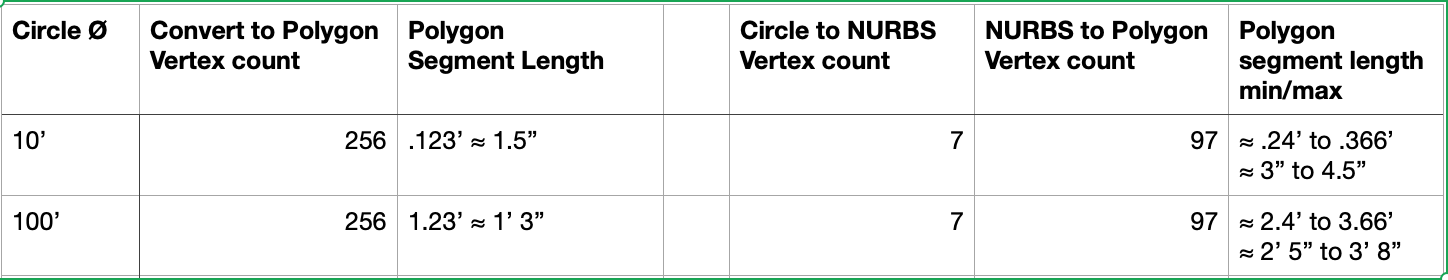
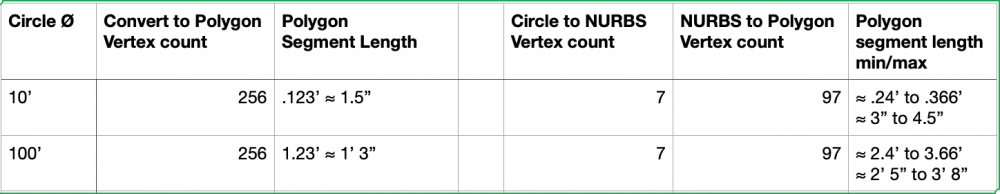
  3. This is another wish to control faceting, especially in 3d geometry operations. Recent posts and many old ones explore the problem from several user experiences. Extrusion, EAP, NURBS curve, NURBS surface, Shells, etc all exhibit faceting. This seems to stem from some software design interpretation of the curves. Curved geometry is generally understood by humans as an analog concept - a circle or other smooth curve is continuous. It has no vertices or facets. The curve can be defined by math. ANY point on the curve conforms to the math. Extrusion, conversion to NURBS, EAP, etc should adhere to the source curve math without creating additional corners or facets! Digital interpretation of curves, including in vwx, is not continuous. Digital depends on plotting vertices along the analog pathway and connecting the vertices with straight segments. The end points of the segments conform to the math definition, but points between do not. (This is less apparent in 2d curves (arcs, polys), but becomes apparent in conversions and use as sources for 3d objects.) More vertices produces a smoother looking curve and less deviation from the math definition. Computers allow plotting myriad points along the analog curve. I’m guessing software (eg Vectorworks) designers decide how many points/segments, balancing performance against curvature excellence. Here is chart with vwx 2d and 3d conversion resolutions pref set to max. It scales, so larger diameters will yield same vertex count and proportionally longer facets. Wish - Lots more points, perhaps 2d and 3d prefs for sooper dooper stratospheric high conversion res? Or some other way to conform more closely to analog understanding of continuous curves? -B
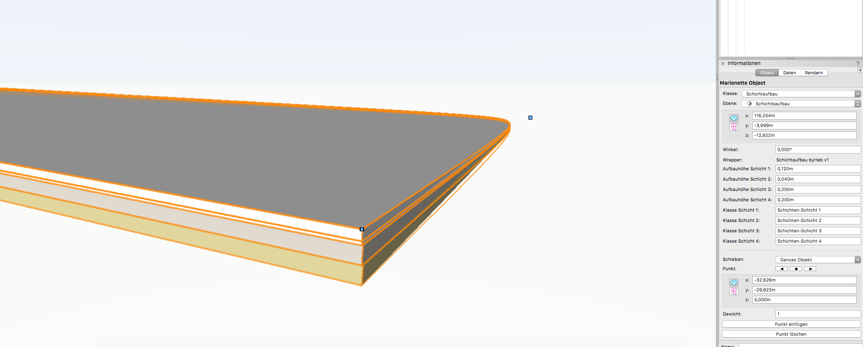
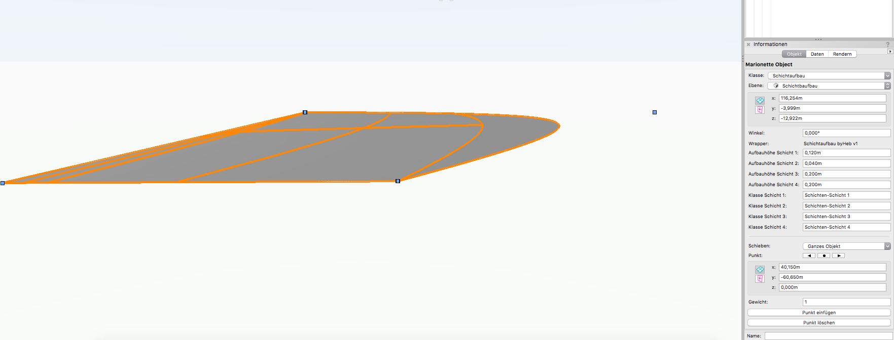
  4. Hey there, I am working on a small tool that creates material layers with a defined thickness. My control geometry is a NURBS curve. I am dealing with two problems: the first one: Vectorworks crashes when shell thickness equals zero. the second: in some cases the network isn't able to generate the shells, all I see then seems to be a NURBS surface I attached the file below... Maybe someone has an idea how to fix it? Cheers! Schichtaufbau.vwx
×
×
  • Create New...