Search the Community
Showing results for tags 'marionette'.
-
Hello everybody Can anyone tell me if there is a Marionette that can create a plan list for me? If so, where can I download it? Thanks in advance Micha
-
Im trying too work out a Marionette that will let cables connect to devices. Kind of like a connection point that I will add to symbols. Can anyone explain this in a simpler way. Im basically trying to make a small AV symbol like ConnectCad uses. I just need a simpler version. I m willing to put the time in. I just can figure out how to plan that Marionette.. I have watched all the videos. I just can seem to grasp what i need to start with for this item.. PLEASE HELP
-
Hi, I'm hoping for an easy fix I've missed in my googling. I want to be able to change the colour/ attributes of a Marionette / object node from the object info panel or in such a way that it is easy/ quick to customise. Thank you for any help in advance. Kind regards, George Marionette - 4 Square.vwx
-
Hello, Although I have been using Vectorworks for many years I have never had cause to venture in to the world of Marionette and am looking for a little guidance. I have an imported DWG file that has a number of focus positions denoted by a circle and a text numerical reference. I would like to try to write a Marionette script that will take the centre point of these text objects and create focus points at those coordinates, and ideally take the text and use it as the focus point name. Id be grateful for any pointers to set me in the right direction. Cheers. Keith
-
I am trying to figure out if there is a node or if it is possible to code a custom node to "Send To Surface" where input objects can be sent to a Site Model?
-
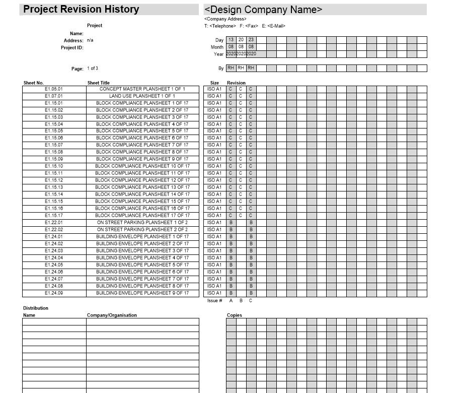
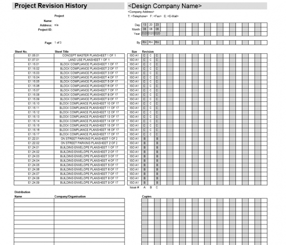
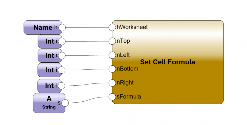
Hi There, I'm having trouble creating a revision history worksheet from my title block borders. As shown in the screen shot below you can see that the revision number keeps repeating the current revision as oppose to the revision the drawing had when it was issued . I though I might be able to fix this myself using the Set Cell Formula, but I can't get that to work either 😞 Thanks for your help!
-
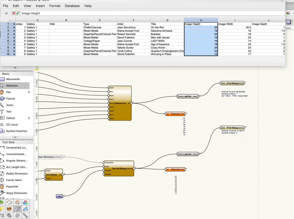
Hi Everyone, I'm having an issue with the add list node. If I create a list with the ordered list node and run it in, everything works well, but if I extract that information from a worksheet and run it into the node the result is 0 items. I've tried formatting the data as different number types (dimension, general, decimal) but same result. Anyone come across this before? Thanks! -Chris AddList_Debug.vwx AddList_Debug.vwx
-
Heya Team, I am trying to create a layer filled with symbol insert wrappers. I have got it working but it always inserts the symbol on the same layer the wrapper is on, where do I place the command to tell the wrapper which layer to send that symbol to? Thanks in Advance!
-
How can I generate a cut list automatically from a 2D drawing? I just want to draw shapes, give each a unique code that shows up on the drawing (with the shape, like a data tag) and simultaneously puts the objects dimensions into a spreadsheet. I have retrofitted the space tool to do something like this, but would love to have this as a simple tool...
-
Hi there, I try to work with the Insertion Point of Symbols. The problem is that the "Get Symbol Location" Node only creates the X an Y Axis of the Symbol but not the Z Axis Is there some other node which can display the Z Axis? I've seen the node "Get Z at XY", but the problem is that this is the highest Point of the 3d Symbol at the Insertion Point and not the insertion Point itself. Thanks in advance Tom
-
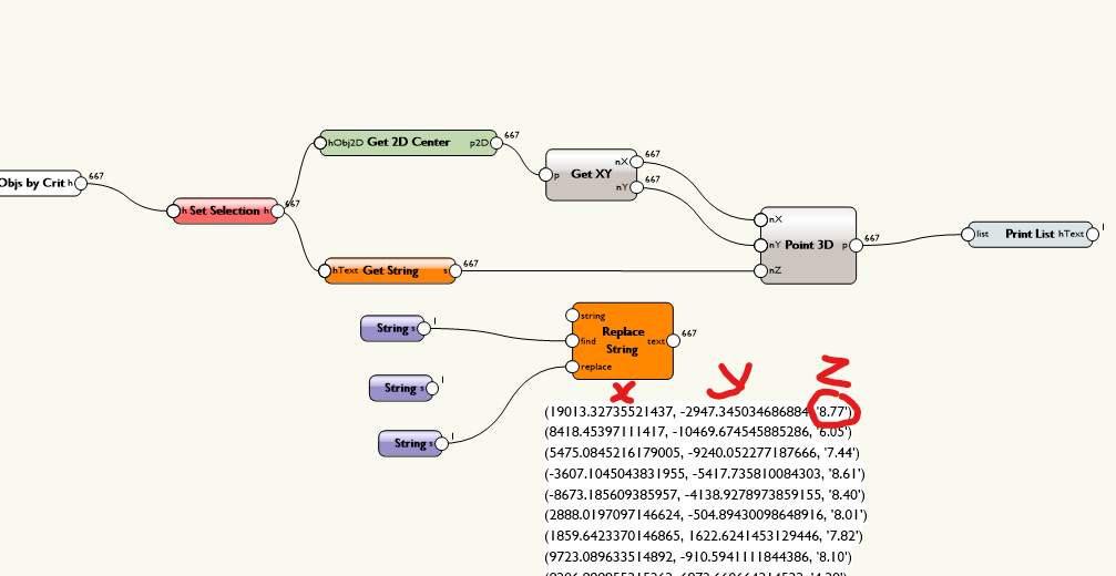
Hello, I've a file with lots of block text and I want to create 3Dlocus at each text. It's Ok to Get X and Y coordinates. The Z value is the text object himself. The GetString node returns a String, but I need to convert this string to Real number. Is somebody have an Idea?

-
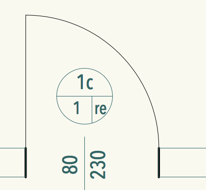
Hi all, I am trying to create a very simple 2-D Door Jamb (see PDF attached for visual cue) which I want to use for a Door Marionette that I created. And I have tried for hours with different nodes to get the result I need but it is not working. So I ask, if my starting approach is the correct / efficient method or is there a better one that I may have not considered? 2-D Door Jamb - Values and Parametrics The 'bold black' shape is created by individual lines with fixed points which I want to be temporary as highlighted in red. Those are values I want the user to input. I.E. if the wall thickness (a) is 200mm, then Door Thickness line will change to accomodate the change in wall thickness(b). Also, I want there to be a fixed length of 45mm highlighted in blue, which will then give the door thickness (b) distance. Makes sense? To make it more complicated, I want the option to add a constraint of the wall thickness (a) value, so it does not go lower than 60mm. I hope I am making sense with the diagram below. I have tried various methods to 'Get Distance', 'Find Points in Polygon' but I just dont seem to understand how to draw the polygon shape and also add the constraints. 20200205163000.pdf
-
 Hello All! I´m trying ot get the hang of creating customn wrappers, commands and objects, but I´m hitting a brickwall here. I manage to build a simple "extrude rectangles" network, but as soon as I wrap it, it doesn´t work anymore. From the non-working wrapper is evident I won´t be able to build a commnad... I´d very much like to build commands with the "Sel=true" criteria. Any hints to make them work if and when I solve the first problem?? I attach the simple examples just in case.OBJ by Criteria.vwx
 -
Is there a marionette node that better pulls the true length, width, and reference point of a rotated rectangle? The basic one basically pull the bounding box dimensions of a rotated rectangle and not true length, width, or point of reference.
- 6 replies
-
- 1
-

-
- marionette
- rectangle
- (and 1 more)
-
Hi guys, I created a Marionette object and I'd like to convert to a custom plugin. Is there a simple way to do it? Or is it maybe possible to just copy the code of the marionette object and create a custom plugin object manually? Thanks in advance VvierA
-

Marionette - Separate class for wire color
Benson Shaw posted a question in Wishlist - Feature and Content Requests
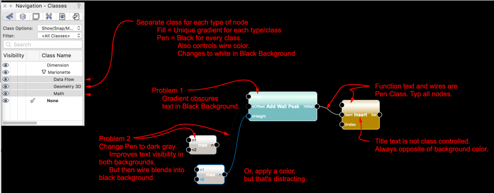
Marionette node input/output text labels can be obscured by the node gradient fill when drawing is toggled to black background. Wish is for a separate control/class of the wire color so that text can be black (or dark grey) when drawing is in black background. And wire can switch from black to white. Setup General condition when toggling black/white backgrounds is that "pure" white and black attributes switch. Dark grey (impure) does not switch. Marionette nodes have a gradient fill - white to a color (different color for each node type) Node input/output text labels are same class as wires. Label pen color for white background is black, and switches to white in black background. If pen color of a node is changed via class or attributes palette, any wires for that node change to same color. Separate classes for labels and wires would allow always dark text (dark grey), AND wires always opposite of background color. -B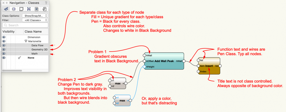
-
So I want to create a series of symbols that have Marionette wrappers embedded within them. The marionette wrapper would take data from an attached record defining the shape and depth of the symbol. By doing this we can have one symbol that is for all telecom hand holds and by changing the records the marionette wrapper would change the shape and depth of the symbol to match. We could then have one standard top view for a legend but on dimensional control plans we could show the accurate size and have a worksheet that quantifies all the hand holes by size. Not sure if all this made sense but the is the gist of it. Any help would be greatly appreciated. 0485 services symbols.vwx
-
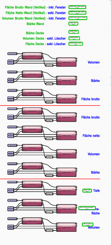
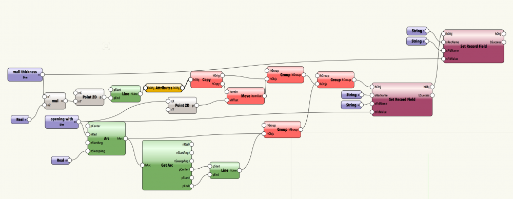
 Hi, sorry, but I cannot find out how to write my marionette object's parameters into database records (or worksheet cells), which was my reason to create them – can someone point me in the right direction? I wasn't able to find example scripts ... My objective is to create a door schedule that uses simple, 2D, self-made, non-IFC door symbols with data stamps, to be placed on 2D-drawings (draftsperson does not use walls, just lines). Most parameters will be strictly database records that never appear on the drawing, but WIDTH, WALL THICKNESS, and OPENING DIRECTION (L/R) should be 'hard-wired', i.e. taken from the plan, in order to avoid common mistakes. My first approach was to calculate opening WIDTH and wall thickness from the bounding box of the door symbol/group. This works fine, but only as long as the wall layout is strictly cartesian and the doors are not rotated or mirrored. Also, we would like to use door symbols that are larger than the opening width (including frames etc.), so we would no longer be able to calculate the width from the bounding box, wich seems to be all a worksheet can access. Or is there a way to access data from objects INSIDE a group that is listed on a worksheet? So I created a marionette object that draws the door opening based on parameters, because I expected it would be easy to access those parameters from a worksheet or to write them to an attached database record ... but I find that task surprisingly difficult. Am I missing something? So far, my marionette network, run as a wrapper, can draw a door based on two parameters OPENING WIDTH and WALL THICKNESS, and attempts to attach a pre-defined database record to that object, where it correctly fills the fields for wall thickness and opening width. However, the result is a simple group (not a PIO, so it cannot be manipulated by parameter later), and it is nested twice in otherwise empty groups, unnecessarily. If I convert the wrapper into an object node, it becomes the expected parametric plug-in-object that I can modify later, but it does not attach a database record to itself or writes its data to a record that I attach manually. What am I doing wrong? test door database.vwx this is what the door symbol plus tags should look like this is my marionette object node (so far, without tags, but okay ... if it only wrote to the database !!!
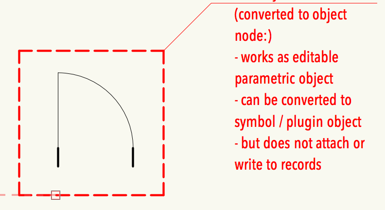
-

Default and Custom Value input in the Object Info Palete
Dishav Vasudev posted a topic in Marionette
Hello, I'm new to using Marionette Tool in Vectorworks and am finding it very useful for simple parametric object creation. I'd appreciate to know if there is a way to set the marionette-object with pre-defined values which can be selected in a drop-down selection in the object info palette? And, to take the above further, it is also possible to add a 'Custom' option where the user can add their own value and the marionette object will follow? To visualise this, imagine a rectangle with 'Width' and 'Height' defined and user can select it from the Object Info drop down but those 'standard' value may not be suitable (due to real-life use) and needs to change that rectangle to a project based value, therefore also a custom option in the drop-down where the user can specify 'Width' and 'Height'. I don't wish for someone to make the network for me, I'd like to learn and build it myself Thank you in advance. -
Hello there! I'm trying to generate a marionette script for automatically naming and generating classes. What I want it to do is, that a class is generated, and the selected object is put into the class. The naming scheme is mostly the same, so I tried to generate a dropdown menu and based on your choice there should be another choice. At last you put a text label in the third part of the name. So for example: part a, part aa, my text. I tried to put a few nodes together, but I am new to marionette. So I have the problem that once I select the first choice, the second is not determined by that and it does not work as intended. In general the way this marionette works is incredible! I really do enjoy playing around with scripts and nodes in the forum, but since I am not educated in this field (yet), maybe someone with more experience can look at the attached file (it is a student version .vwx) and help me out! Thank you in advance! Kind regards Ben
-
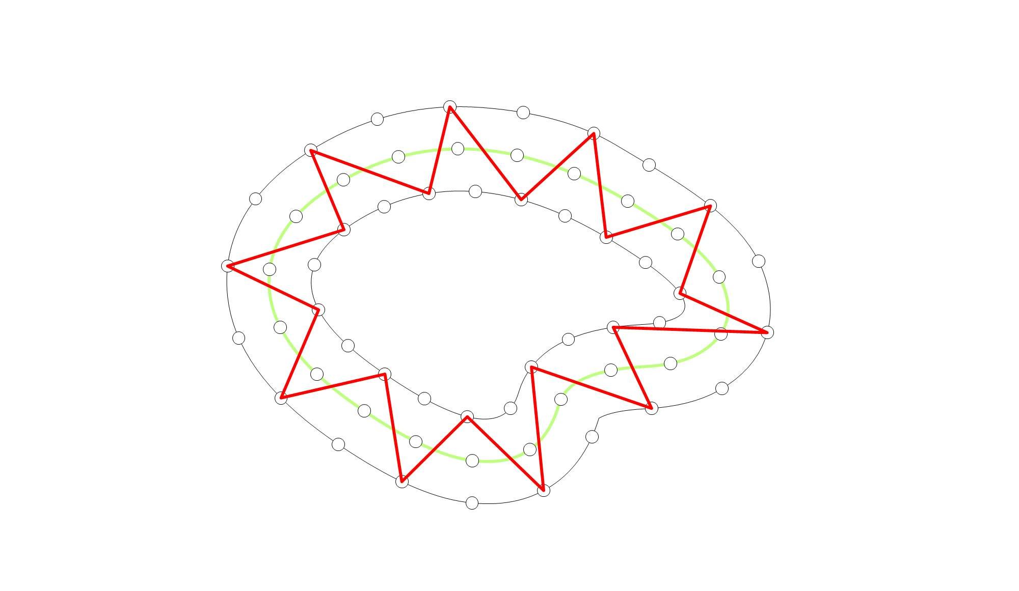
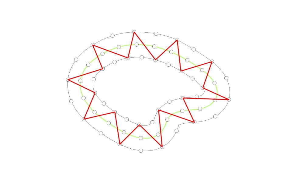
Hello, I'm looking for some hits how to solve the following problem. I want to create a script that converts base curve (any Nurbs in 3D, green curve in the picture) into zigzag line around it, but on the same plane (red curve in the picture). I thought it might work in following steps: Base curve (green) -> Offest on both side -> divide curves into same number of points -> sorting points -> creating nurbs Curve based on sorted list But this fails on sorting step. I had other idea, using vectors: base curve (green) -> points on curve -> Perpendicular Vectors from these points -> every 2nd Vector turn -180deg -> move point along vectors in both directions -> creating nurbs Curve based on moved points But I don't know how to create adequate Vectors in 3D. I will most grateful for any help/hints how to solve this.
-
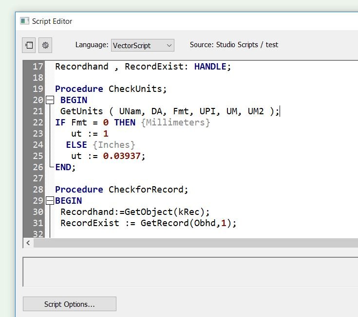
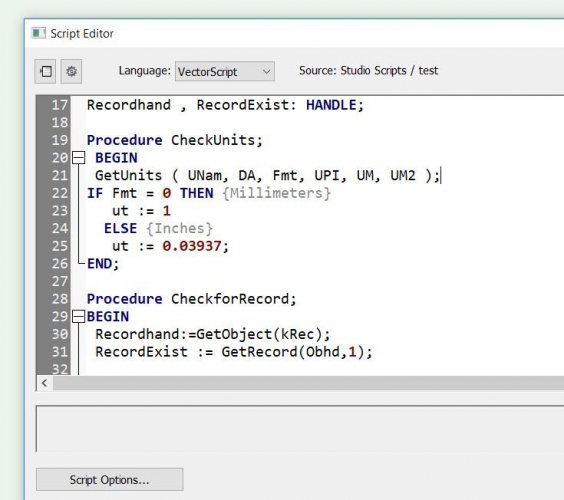
I am creating a Marionette network that will create an object (trade show graphic) based on input dimensions and then populate a record with pricing ($/sq.ft.) and dimensions in inches and dimensions in millimeters. When I change the document units things get thrown off. Is there a way to have the network check the document units so the network can apply the appropriate calculations to get the same output regardless of how the document units are set? See uploaded image of how this procedure looks in vector script. Seems like there should be a Get Units node. Any help is greatly appreciated.
-
Hello! I have question. How can I connect n-th element from different lists? The situation looks like this: there are two circles and equal numbers of points on them. I want to connect points of the same index on both curves (the 1st on one curve, and the 1st on the 2nd one, then pair of 2nds points on each curve, then 3rd and so on). I know that there is a way to do this manually (List Explode node), but how can I do it in more parametric way e.g. if I do not want to specify the exact number of points on curves, or I simply do not know how many of them are needed. Connecting Nth element.vwx
-
Hi does anyone know how to grab the texture of a group an display it in a worksheet? I can get the texture of objects with using "Function" and "Object Texture", but even though the group is covered by a texture I can't work out how to display it in a worksheet! I have thought of using a Marionette, to put the texture name in a record and then reference that, but you can't seem to get a texture name from a Marionette either!
-
Hello, I have a lot of Wraps I have to run before I export my IFC File. (about 25 Scripts) - Is is possible to make a "Mother Wrap" who runs all the wraps in a specific order ? Best regards,