Search the Community
Showing results for tags 'led screen'.
-

LED Screen Tool: Curved Screens
Andy Broomell posted a question in Wishlist - Feature and Content Requests
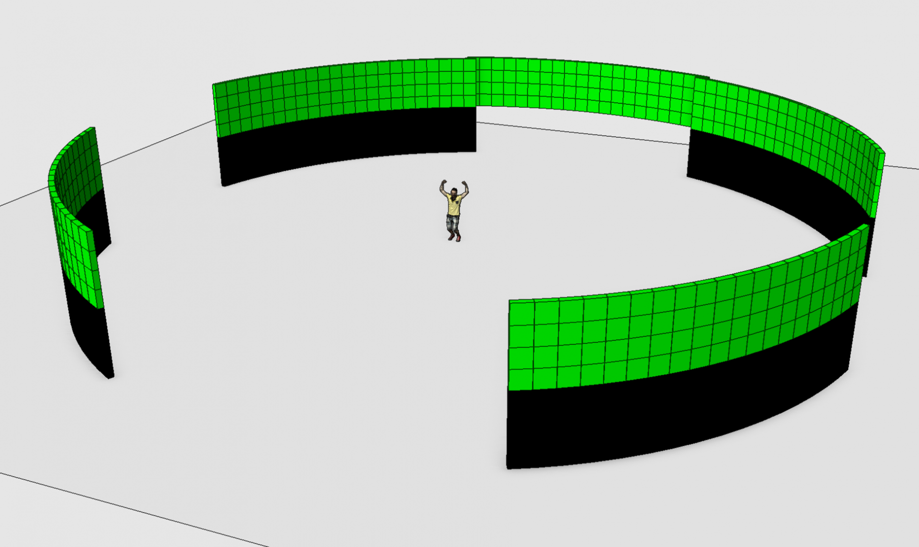
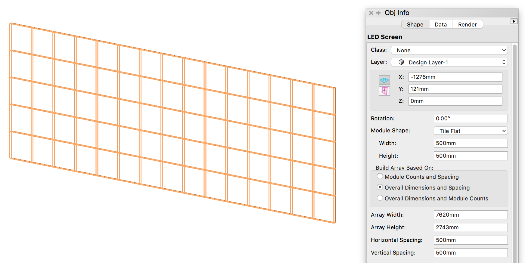
It would be great if the LED Screen tool had a way to create curved screens, such as this: Currently you can create flat screens with the LED Screen tool: Adding the ability to create curved screens could be accomplished by: Adding a parameter to specify an arc diameter Adding a parameter to specify an angle between each column of modules (a common approach since there's often specific curving block hardware available). For example, I could say I want 7.5° between each column of my 500mmx500mm modules. While I can model curved screens with simple extrudes like I did above, the LED Screen tool has many advantages, such as: Ability to extract data into worksheets. Flat screens and curved screens are all the same PIO. Built-in text labels. Automatic 2D representation with 2D solid fill. Mapping a single image texture across the modules. Automatic calculation of number of tiles within specified screen size. Most importantly... I can change from 500mm square tiles to 480mm square tiles and not have to start the whole process from scratch. Manually distributing the shapes accurately along the curve is a laborious process. If the LED Screen tool could do it all for me I would be a very happy camper. -
2023-07-25_20-35-53.mp4
- 3 replies
-
- led screen
- shaded
-
(and 2 more)
Tagged with:
-
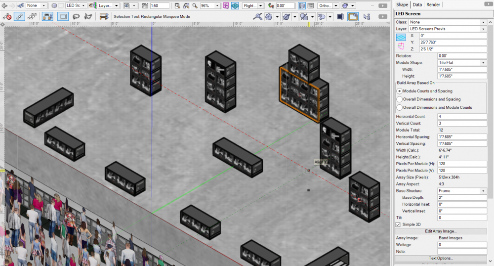
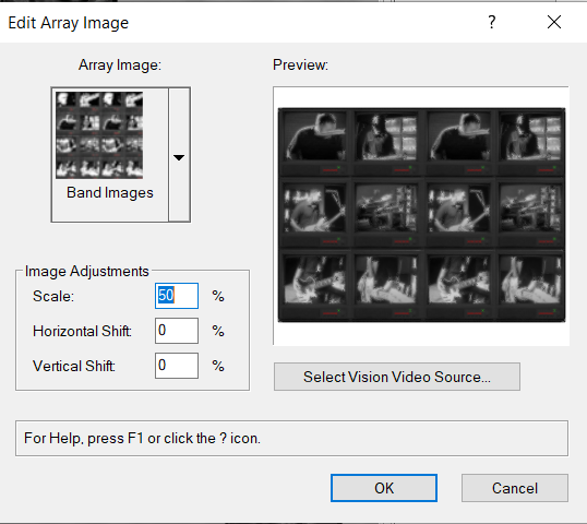
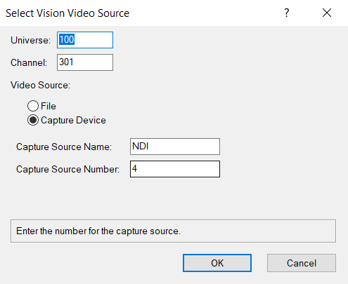
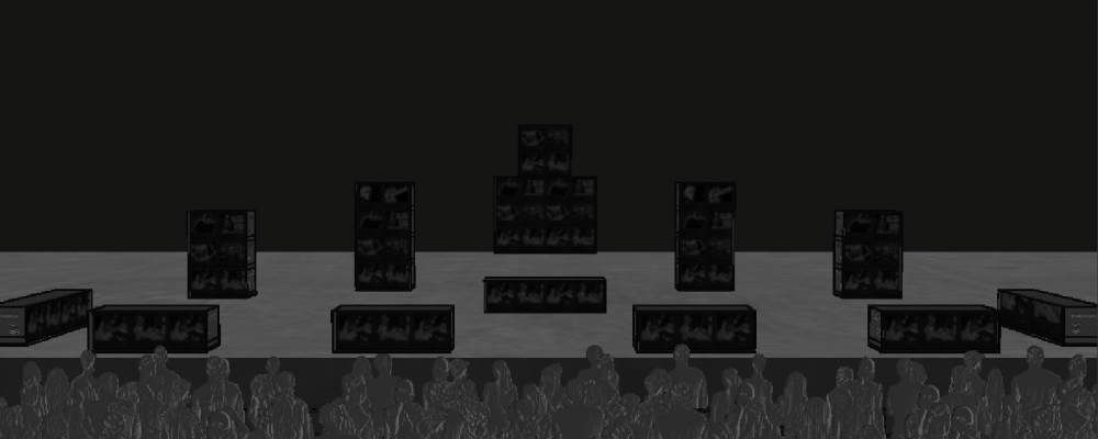
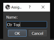
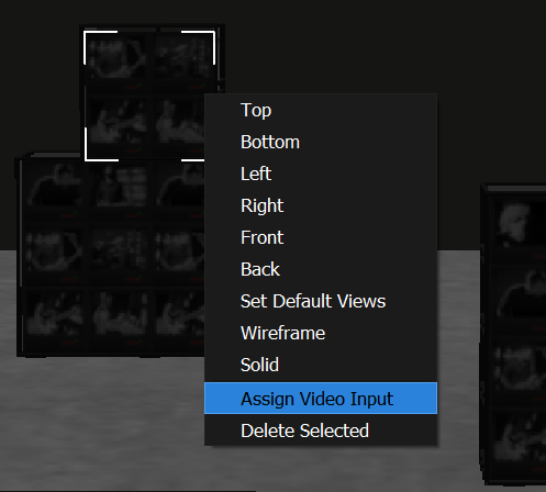
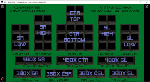
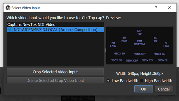
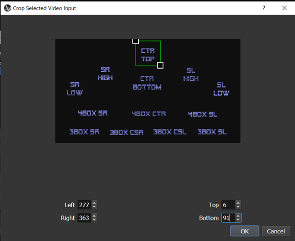
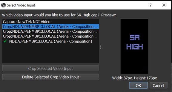
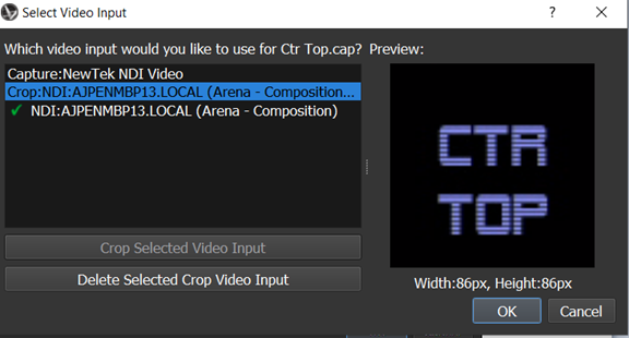
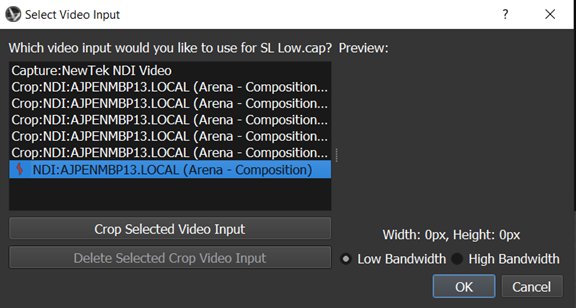
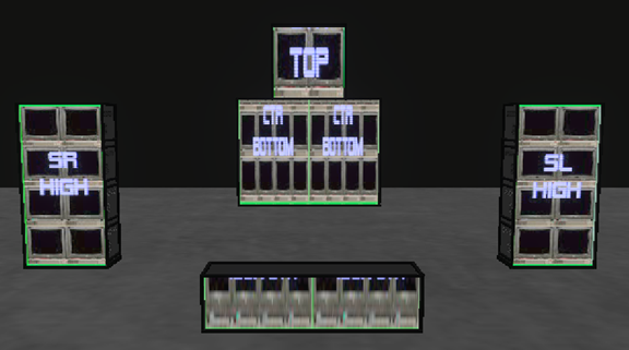
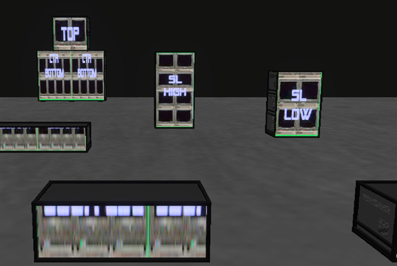
Hi Y'all... Pour yourself a coffee and tuck in; this is a long one! I'm having trouble mapping an NDI stream to various LED tiles placed on stage in set carts. The set looks like the following screenshot. All of the display surfaces are LED Screen plugin objects with dimensions and pixels set correctly in the OIP as indicated: The image on the LED screens is set in "Edit Array Image" where a custom texture is selected. Notice that the Scale is set to 50% to get the image to display correctly (the illusion is a stack of TVs with different images). The image used for the texture is only two TVs wide, so this makes sense as applied to the still image in VWX. Changing this scale, however, has no effect on the eventual video mapping problem that we shall see in Vision. I tried exporting MVRs with all of the Scale adjustments in this menu set to 100% and had the same results that are illustrated below. I also wonder what the "Capture Source Name" and "Capture Source Number" are in the "Select Vision Video Source" dialog. These names do not correspond to the names that Vision ends up asking for, and you could put Fred or Ethel in the "Capture Source Name" field and you never see those names come up again throughout the process: But let's not get distracted... OK, so now we move over to Vision, after exporting the LED tiles in their own MVR. The set carts that they travel in get exported as a separate MVR to keep things organized. These two MVRs plus my Amphitheatre MVR merge together in to this model: Let's begin by selecting our first LED array (in this case the 4 tile square array top center) and choosing Assign Video Input: We assign the video input a name: The video input is fed via NDI from a MacBook Pro running Resolume Arena. The NDI monitor on the Vision PC shows a smooth, steady video image in real time: We find the 1920x1080 NDI input that is being scaled by 1/3 to give us a raster of 640x360 for use in Vision. So let's crop the NDI stream! I scaled my 1080 template down to 640X360 in Photoshop to determine the exact corners of every crop and wrote them down (analog, in a notebook with a pencil) because the cropping tool in Vision is rudimentary at best. You can't zoom in on it, there's no grid or snap guide... best to use the tools in Photoshop and write down the pixels. So we get our square crop for our square video surface: And we do it for each of the LED screens in the model: During this process, plan to spend a lot of time looking at this screen, waiting for Vision to "see" the NDI input that it "saw" just perfectly moments ago: Eventually we have created 13 separate crops of the NDI raster and mapped them to our LED screens. And here is the confusing result: Note the different scaling of the crops! Nothing seems to work out right, except the SR High and SL High set carts! The 2wide x 4high carts are the only ones that display the crop faithfully. The Ctr Top crop is perfectly square, mapped to a perfectly square screen. It ends up stretched vertically. Ditto the Ctr Bottom... that one is stretched vertically and doubled. The math certianly does not work for the downstage 3wide x 1high boxes. Playing with the texture scaling and offset in Vision does not help... You can't fix an asymetrical scale as is occuring here. If we use Vectorworks to create an LED screen and send it to Vision, and Vision has the ability to crop an incoming NDI stream, why doesn't this just work? I did try sending the crops from Resolume as separate NDI streams but Vision could not see them as separate. Any help would be appreciated. Getting this model to work will greatly increase the chances that it will be useful to me before we get to rehearsals. Thanks peace aj peace aj
-
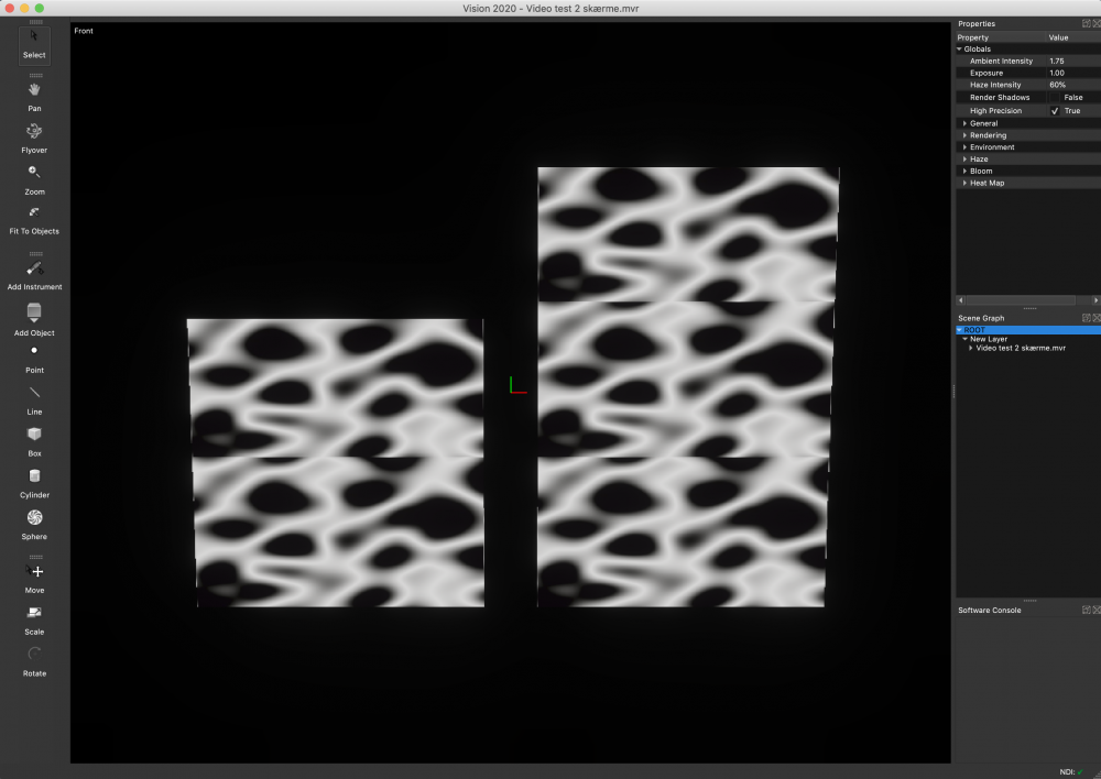
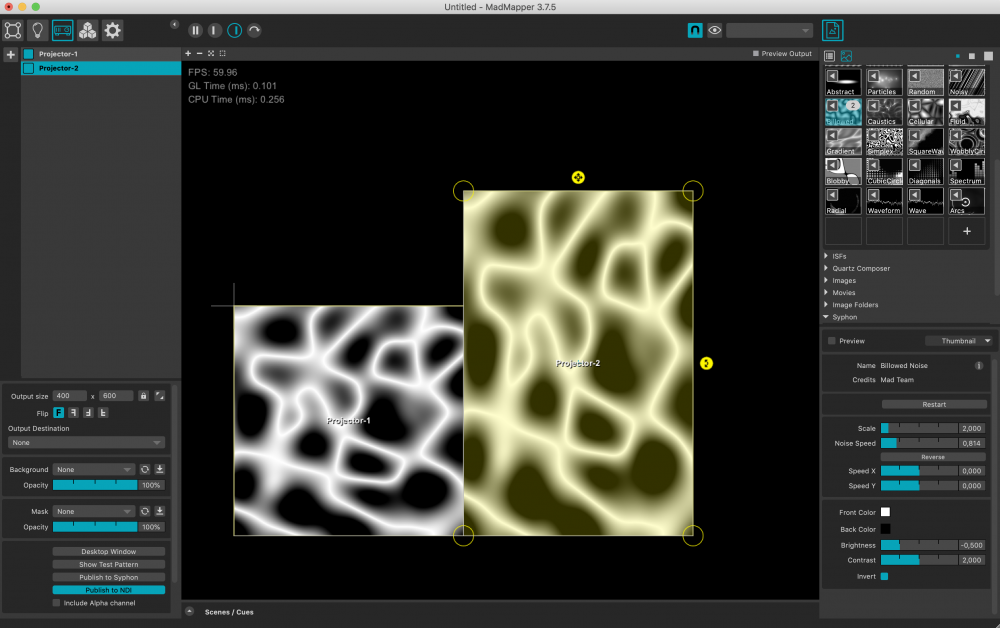
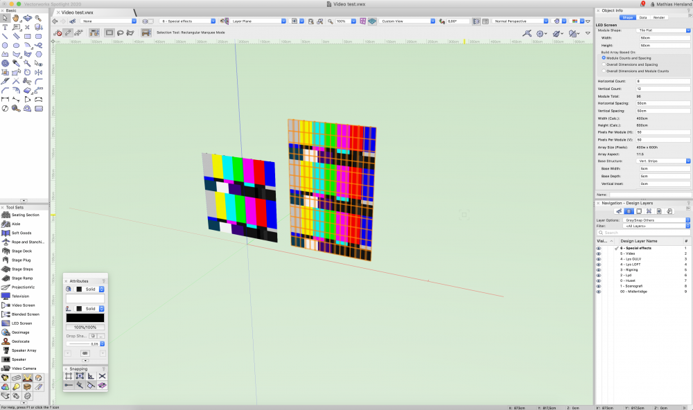
Hello everyone Hope you can help me on this one. I am trying to make some LED screens. But vision seams to duplicate my video input to fill the screen. I made the file in Vectorworks, and exported it as MVR, to get it in to vision. I am sending NDI from Madmapper. I made to outputs here, one for each screen. Both mad mapper outputs has the same resolution as the screen set up in Vectorworks. It seems I am missing some kind of scaling or alignment option? My Vectorworks settings for the screen is here. It is the same situation, when using my webcam in my laptop, as input. Do anyone have experience with this? Best from Mathias
- 4 replies
-
- ndi
- video input
-
(and 1 more)
Tagged with:


