Search the Community
Showing results for tags 'led'.
-
I had a quick search but I couldn't find anything. Is there a function in Vectorworks Spotlight 2017 that allows me to insert a lighting symbol at different lengths? So the length of the symbol is variable? For instance, when I draw LED tape the length is never a set amount. It is normally set to the size of scenery or buildings. Which means there are sometimes over 10 different lengths the symbol can be. Which makes reports and instrument summaries a nightmare. I think it will be really useful if there was a tool in which you could choose the type of LED Tape (For example RGBW @ 8w per meter). And be able to draw the tape live on the plan. Sort of like how the truss tool works but more of a click and drop like system (So you can create curved tape). It would then be useful for this to automatically be a singular lighting symbol and add information to the `Light Info" records. For example standard lantern information such as Unit Numbers, Circuit Numbers, Purposes, Positions. And additionally new information such as automatic Tape lengths, splits, and final wattages calculated from the watts per meter given and the variable length. I think when it comes to the instrument summary it would be useful if there was just one symbol that showed a section of the length. Named for example RGBW LED Tape. At the moment this is possible but the build list is flooded with 10 different lighting symbols for LED Tape. I know you can choose to hide/show symbols in the build list but symbol management would be so much organised. Let me know if this does or does not exist. Hopefully, I haven't been too oblivious. Many Thanks, Ryan Lawrence
-
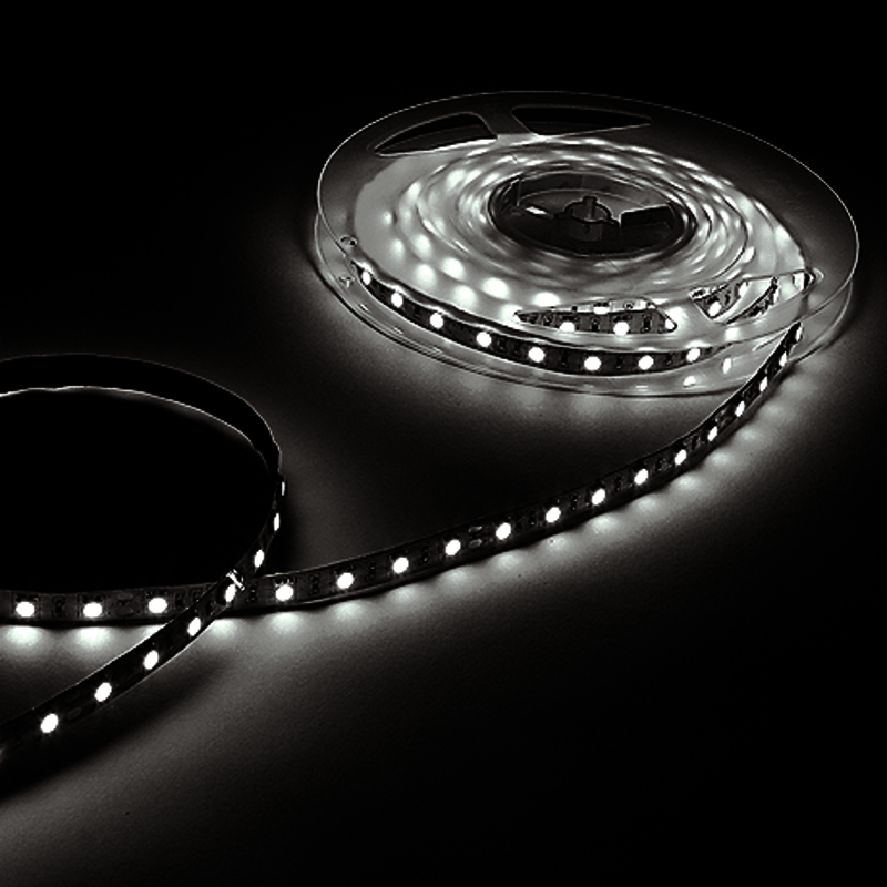
Hi all Do any of you have a trick for visualization of LED tape, and Digital Pixel LED tape? I have some custom fixtures that I use in different cases. The tape is like this one: Best from Mathias
-
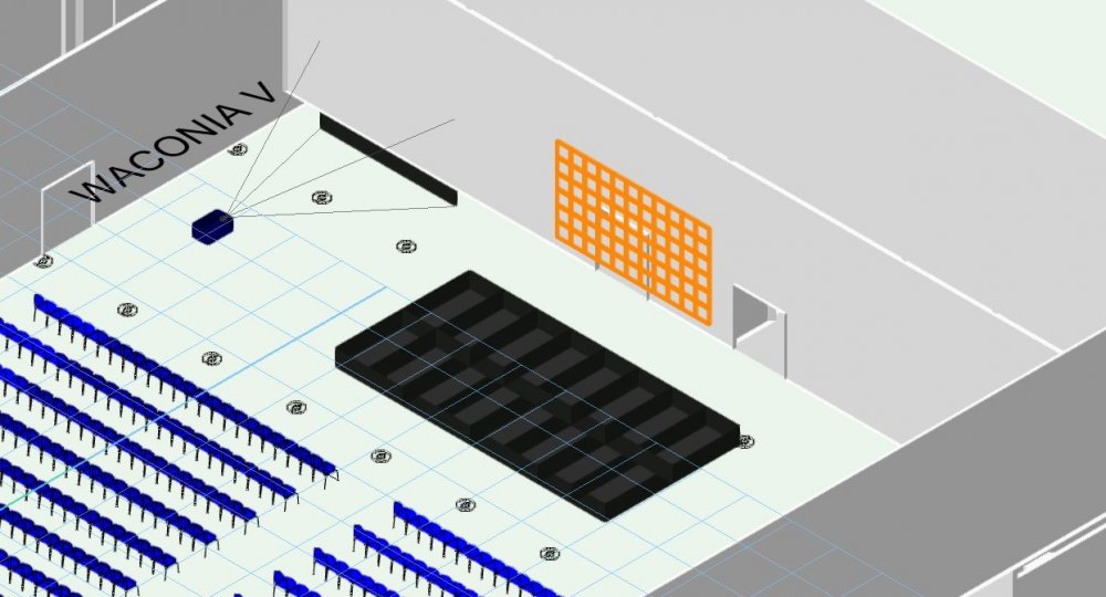
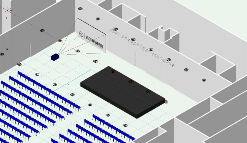
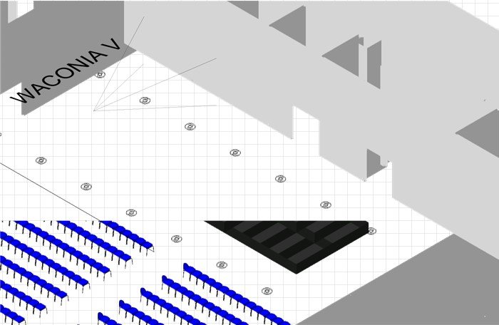
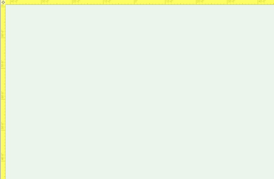
LED Screen tool is currently completely unusable for me. Whenever I insert an LED Screen object, I get very strange behavior in 3D views. Objects disappear or appear incorrectly. Which objects appear at all, and how they appear changes depending on zoom and viewing angle in flyover. Bug carries over into viewports. Additionally, ONLY after inserting an LED Screen, every time I enter flyover WITHOUT an object selected I get a blank canvas with yellow highlighted rulers. Attached are screenshots of a basic event layout in isometric view before inserting the LED screen, after inserting it, showing the screen selected but invisible, hollow stage(?) missing doors, 3D text showing through wall... just a mess. And a viewport of the same that's even more fun. For now I will use projection screen objects to fake it, but this is extremely frustrating. I was away from VW for most of the pandemic because, well, not a lot of live events to draw. This issue is new for me since updating VW and returning to this side of the work a month or two ago, but is consistent. The first time it occurred, I thought I just had a corrupted file, tried copy-paste into a new doc, no luck. Re-drew the whole event, same issue. I'm on a brand new installation as I've moved to a network server license, and it has persisted exactly the same way. Any help appreciated. Am I alone in this? Housing First 2021 Mystic v2.vwx
-
Could be usefull to have a tool that allow to build a strip LED with some parameters like brand of LED, kind of LED (white, multichip etc...), size of the strip, distance between LEDs and soo on
-
Hello all, I am going to begin creating symbols for PixelFLEX LED screens and would like some user feedback. In the past LED video screens have been either detailed geometry or simple rectangular plug in objects. As a user which style of symbol is preferred for video screens, detailed geometry showing top profile and connection points or simple plug in shapes? Any input is greatly appreciated. Thank you!
- 8 replies
-
- pixel flex
- video
-
(and 1 more)
Tagged with:
-
I had a quick search but I couldn't find anything. Is there a function in Vectorworks Spotlight 2017 that allows me to insert a lighting symbol at different lengths? So the length of the symbol is variable? For instance, when I draw LED tape the length is never a set amount. It is normally set to the size of scenery or buildings. Which means there are sometimes over 10 different lengths the symbol can be. Which makes reports and instrument summaries a nightmare. I think it will be really useful if there was a tool in which you could choose the type of LED Tape (For example RGBW @ 8w per meter). And be able to draw the tape live on the plan. Sort of like how the truss tool works but more of a click and drop like system (So you can create curved tape). It would then be useful for this to automatically be a singular lighting symbol and add information to the `Light Info" records. For example standard lantern information such as Unit Numbers, Circuit Numbers, Purposes, Positions. And additionally new information such as automatic Tape lengths, splits, and final wattages calculated from the watts per meter given and the variable length. I think when it comes to the instrument summary it would be useful if there was just one symbol that showed a section of the length. Named for example RGBW LED Tape. At the moment this is possible but the build list is flooded with 10 different lighting symbols for LED Tape. I know you can choose to hide/show symbols in the build list but symbol management would be so much organised. Let me know if this does or does not exist. Hopefully, I haven't been too oblivious. Many Thanks, Ryan Lawrence
-
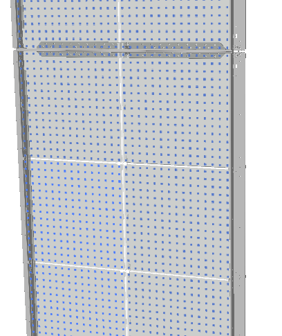
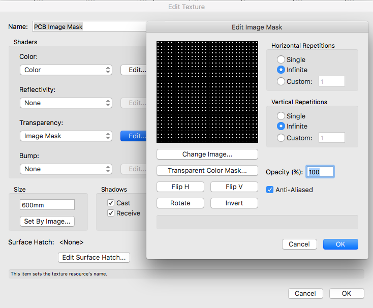
Hi, I am using an image mask texture to simulate pixels on a low res, transparent LED panel. Looks alright, but I would like to add glow to show how it looks with content. I don't necessarily need light from the screen on surrounding objects, but at least a bright "lit up" look on the screen itself. Any ideas how to accomplish this? Texture glow options are not doing anything. Thanks johnq
- 5 replies
-
- renderworks
- textures
-
(and 1 more)
Tagged with:
-
Now that LED's are being used we need Circuit Breaker panel, relay and Contactor symbols to be included in the Spotlight library. These symbols are as necessary as Dimmer rack symbols Its should have reporting functionality as well. **for not fort!
-
- circuit breaker
- relays
-
(and 3 more)
Tagged with:


