Search the Community
Showing results for tags 'landmark'.
-

Drip Outlet: Snaking vs. Branching
loretta.at.large posted a question in Wishlist - Feature and Content Requests
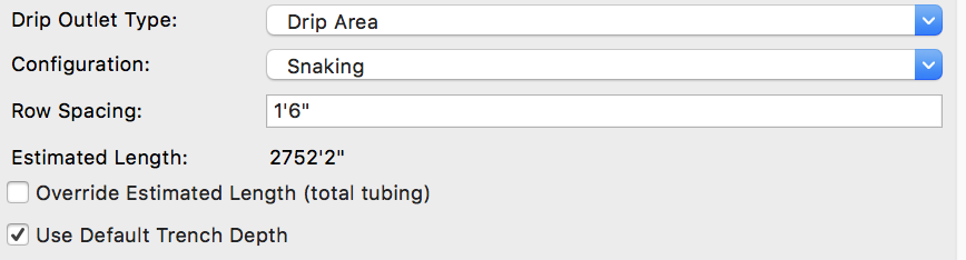
One annoying thing I've notice with drip outlets is that Vectorworks doesn't calculate the total drip line lengths when you specify that you want a branching configuration. It seems to be accurate and give a total amount when you specify a snaking configuration, but you end up with "estimated average line length" instead of total line length on branching configurations. This doesn't seem very helpful. Would it be possible to get the total drip line length on branching areas (excluding headers and footers)?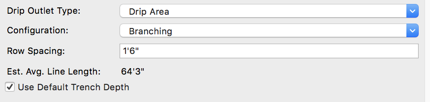

-
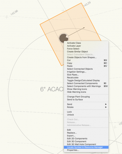
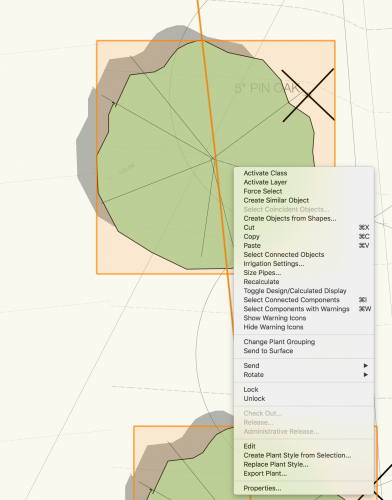
I find right-clicking a regular symbol and then using the "Locate Symbol in Resource Manager" tool to be very helpful. But I wish you could also do this with a Plant Symbol in Landmark.
-
I am trying to show the visual effects of a proposed carpark and visitor facility. I have imported a textured .obj survey file in the form of a mesh (see attached file) and I need to insert the site model for the new carpark into this while keeping the terrain and textures of the surrounding area intact. I find when I try to edit/cut a hole in the mesh to create a space for the new carpark, the texture disappears. Is there a way to 'bake' the texture onto the 3d polygons within the mesh? or can the mesh be converted into another form that allows me to do this? Thanks, Steve
-
My client has an office in China and evidently use a different project or at least one offset from WGS-84. Would it be possible to get some guidance or an update that will add China to the list under Plate Carree, Ellipsoid GCJ-02 coordinate system?
-
Hi is there a decent way to use walls on slopes . The wall should folllow a parallel height to the ground . fixed height on starting and ending point. but should follow down a hill.. if I send my wall to the surface to my model, it follows perfectly on the bottom the slope.but not on the top.. is there any way not to correct it manually ? thanx in advance
-
Working on building a worksheet where clients and users will see the composition of the slab styles that will be used in Hardscapes. I've managed to create in the attached just such a thing but have run into a little difficulty. When using a function to get the thickness of a component it is adding all of the components regardless of which slab they are a part. The attached file has our slabs and the worksheet with the cells in question. My vulnerability is Worksheets and I'm learning more every day but I really could use some help on this one. Your time and effort is greatly appreciated! Have a great weekend! Slab Styles.vwx
-
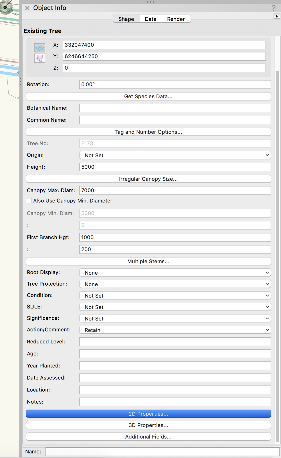
One of our users runs into this issue from time to time where after placing an existing tree and editing several of them the tool locks up as shown below. In the tool itself all options are missing. and the object info palette is missing other things. The only way out of this to close the file and exit VW. Any help will be greatly appreciated.

-
Need Landmark year since 2016. Spanish, English or German language. Make me an offer. My mail: konradanja@gmail.com. Thanks
-
I am a sole practitioner looking for VW Landmark or Designer 2015 or higher for sale. You can email direct at donna@pulsefitnesssb.com
-
Hi, Can someone please help me? Pretty basic I would imagine however I can'y work it out!! How do I get a 3D image of a whole Landscape plan? I can get 3D images on separate Design Layers however can't get an image of the whole project as one 3D image. Please help, its doing my head in!! Cheers Prish
-
Version 1.0.0
130 downloads
This file is most useful for Landmark users but could be adapted to other plugin objects (PIOs). The purpose of these scripts are to take surveys of existing trees that consist of "dumb" data - pieces of geometry and text to label trees on a survey - and convert it into Existing Trees with the relevant text data associated. The first network, "Test Proximity," runs a check to make sure that each piece of text is closest to its associated piece of geometry. This is necessary to make sure that the second script will work properly. The second network takes the center of each piece of geometry and places an Existing Tree there. It will use the saved red symbol in the Resource Manager as a template, so if you use particular default settings for your Existing Trees, you can edit the red symbol. (Some day maybe there will be an Existing Tree Style!) The network will also transfer the text data to your chosen field of the Existing Tree PIO. In this network, it is set to transfer to the Tree No data field. This network could be adapted to other PIOs if needed.- 1 review
-
- 1
-

-
- landmark
- existing tree pio
- (and 1 more)
-
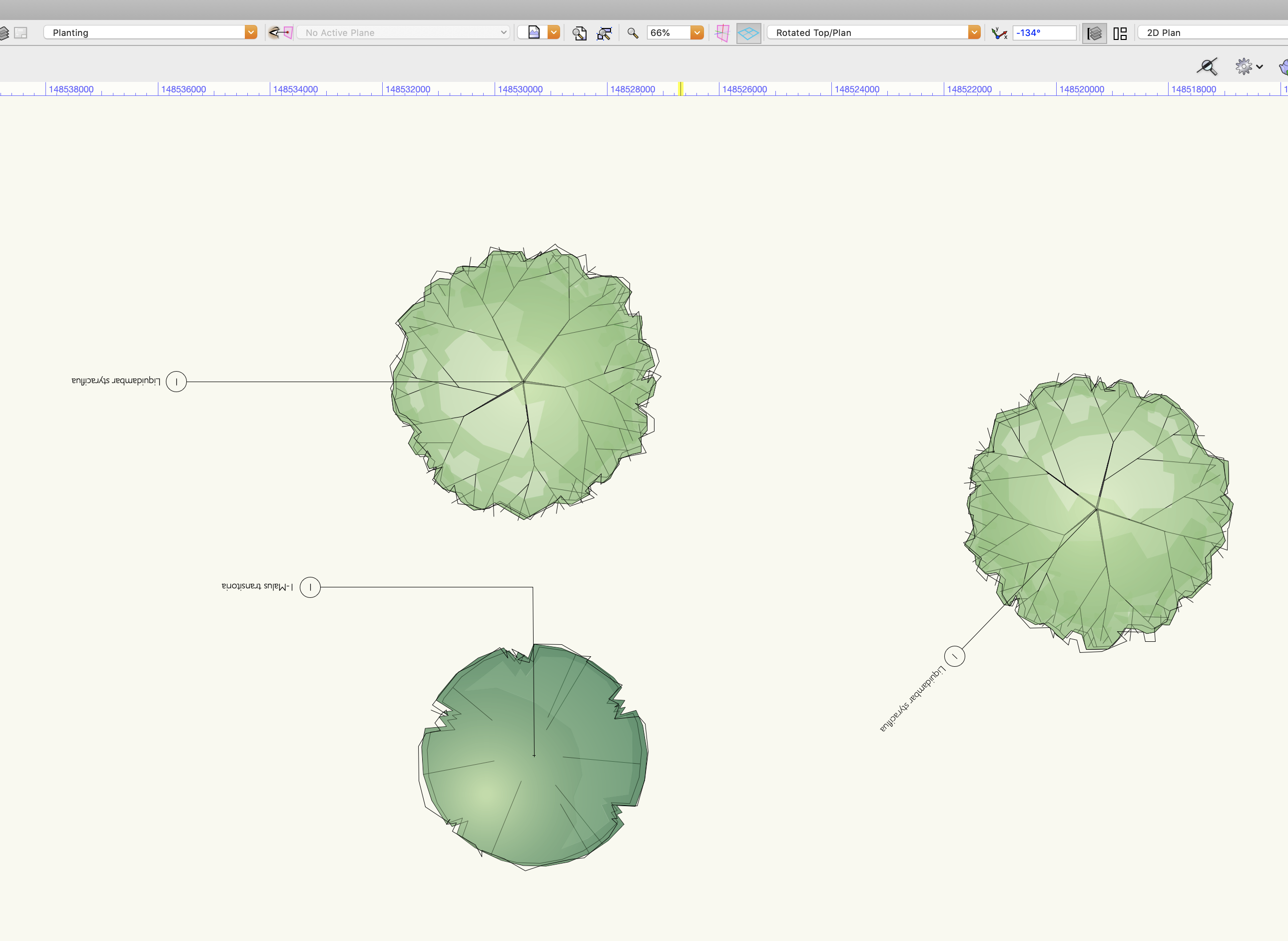
Help please, I am finding it impossible to insert plants onto a rotated plan and get the tags to behave. Desperate to know how to resolve this asap. This plan is rotated -134. The tag text is upside down, whichever way i rotate it. I have tried inserting plants to an unrotated view, but as soon as I rotate to a view that would work on a sheet layer... upside down and all over the place.

-
I have a symbol/ plugin stuck to a layer. I cannot select it - tried classes components tags etc. Select all scoops it up as it deletes with the rest of page, but marquee selection only picks up adjacent objects. I would very much appreciate any advice as to what might be occurring - Violetz
-
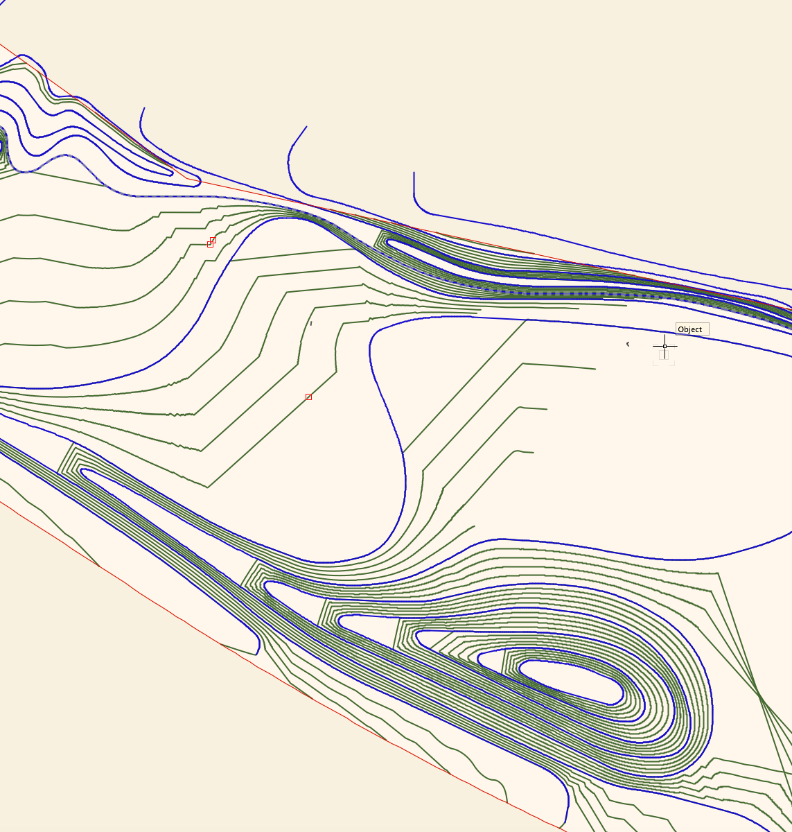
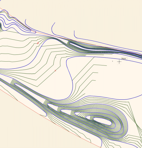
I'm wondering if I'm missing something in terms of the control we have over site modelling in Vectorworks. I've attached a screengrab of a site model I have created. Blue lines are the 3D polyline contours I have drawn and set to 0.5m height intervals, the green lines are the contour lines generated by the site model calculation by Vectorworks, using my blue lines as input data. I have two big issues with this output, namely: I want the model to EVENLY interpolate between the contour lines - for example on the hill to the bottom of the screen grab, I want the mounding to extend evenly to the left, I don't want flat platforms between each level. I want the contours to actually follow the curves I have drawn, and not truncate my contours in large angular lines!! (As seen in the middle of the screengrab.) Is there anything I can do, aside from draw contours at really tight intervals to reduce the visibility of the problem? Is this just how the site modelling algorithm works? I understand the need for a mathematical algorithm, but this results in a fundamentally incorrect site model I can't really use for anything in terms of BIM or production information, as it isn't giving me smooth grades. I'm sure I could fudge it for visualisation purposes, but I need an accurate technical model I can issue in IFC form to provide information for collaboration and also construction. I've turned on mesh smoothing in document properties, which makes the rendered model appear slightly less angular, and also turned on contour smoothing display, but I need an accurate model in terms of BIM compliance and I'm not sure I have this control outwith doing an excessive amount of contour drawing. Is Vectorworks the wrong software for this, or am I missing something? Any ideas or advice would be much appreciated. Lisa
-
At the Landmark 2019 Stake Elevation Z values are in error (always 0 values). In earlier version the problem could be usually solved, if I changed the stake Mode from "Include as site model data" to "Set elevation to Site Model", but now it won't work. Also the existing Stakes from earlier version, which now should be updated, do not update.
-
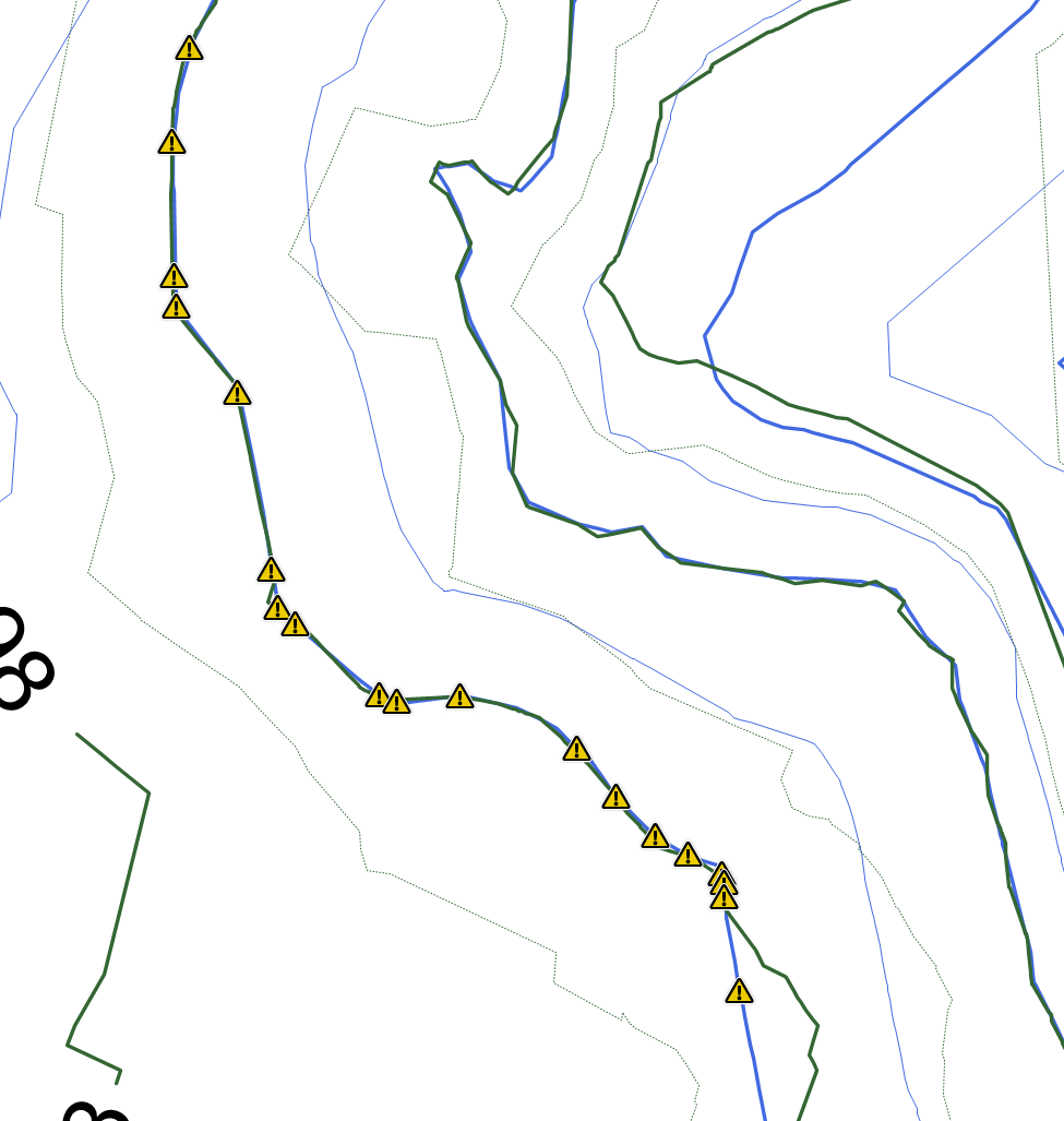
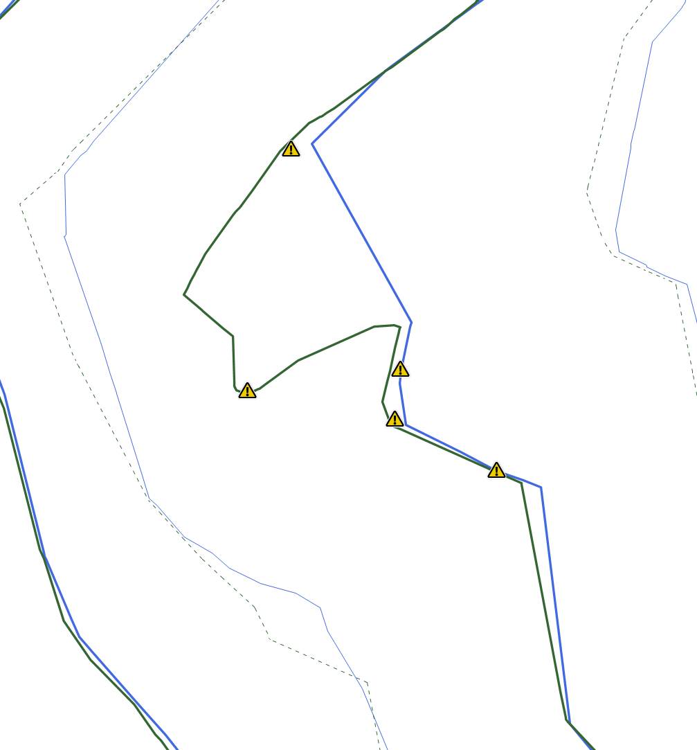
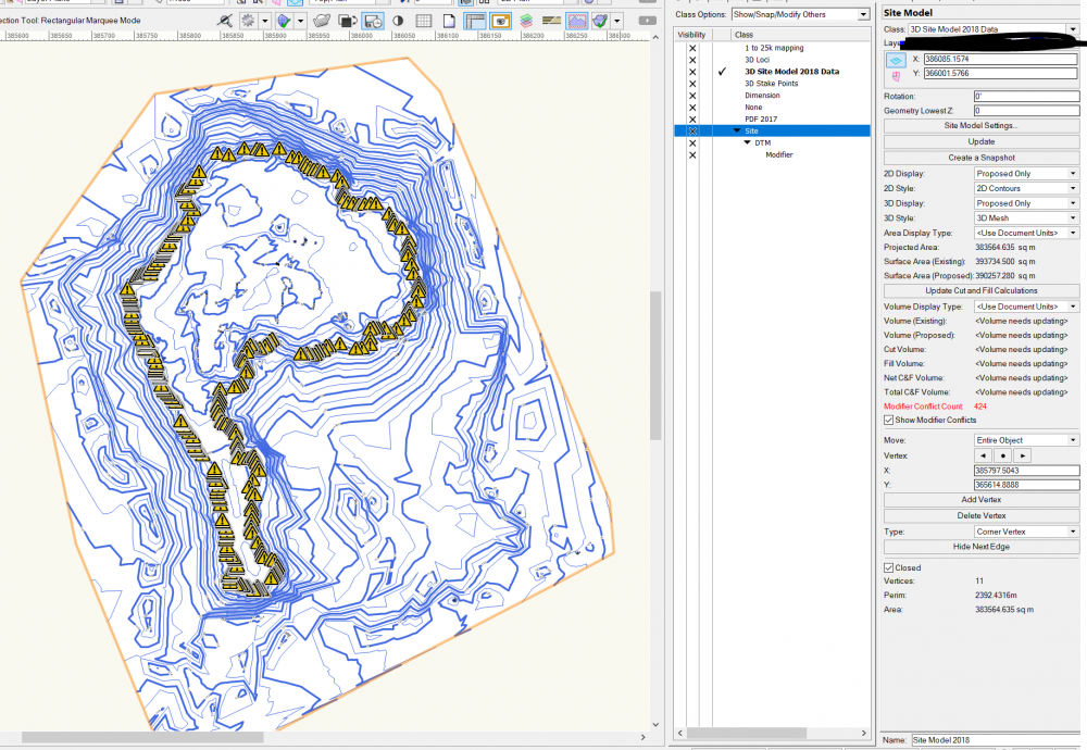
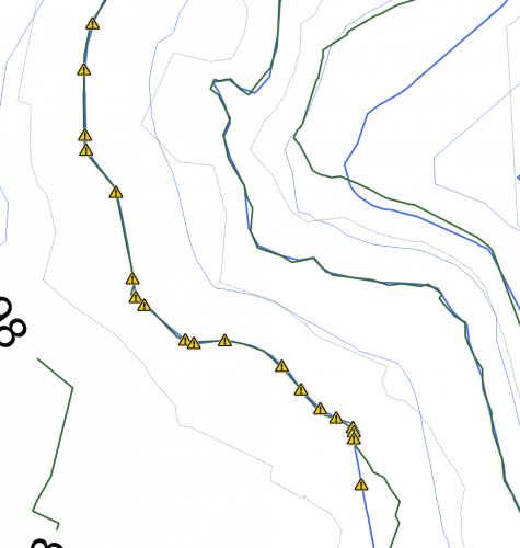
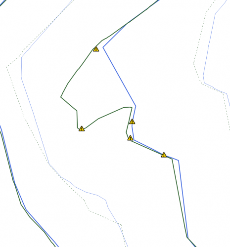
Hello all, I have been working a site model for a quarry. I have two sets of survey data, a topographical survey taken in 2017 in PDF form, and a topo survey from 2018 of the same site in DWG form. I turned the DWG into a site model, and have added in site modifiers of the 2017 data by adding stake points and contours, so that I can compare the two surveys to see how the quarry has changed. I have encountered an issue with a particular contour in the site modifiers, and this contour has flagged up 424 modifier conflicts. I cannot get my head around why only this contour has the problems, and upon clicking the warning triangle it states 'Pads Intersect', however, I have not used any pads, only contours and stake points. Does anybody have any suggestions as to why this is happening? As you can see from the zoomed in images, the modifier conflict warnings are not actually sat on top of 'crossovers' and you can see from other contours that these are not problems. I have attached pictures to help, with the zoomed out image showing only the proposed contours, and the zoomed in showing both (green and blue) proposed and existing. Thanks Joe
-
When doing a large irrigation system (I'm working on several with over 70 stations), the connection time is incredibly cumbersome and slow. The file I am currently working on takes up to 15 seconds to make one connection. Additionally, we have already turned off the Auto Calculation Update feature, so that is just processing time. Some simple math to show you how cumbersome this actually is... 830 outlets of just one type (over 2000 total in the project) = 830 connections 830 connections at 15 seconds each = 12,450 seconds = 207.5 minutes = approximately 3.5 hours of drafting to make the connections. When compared to our traditional methods, we could do this drafting in approximately 1 hour or less. So for 2.5 extra hours, what do I get? Some data attached to the pipe network? That would be great, except half the time there is at least 1 error for every 20 outlets, which has to be found, diagnosed, and corrected, adding at least another hour to the mix. I get that we are supposed to be moving into the "smarter, not harder" category, but this is only coming at it from the "smarter" perspective while making it a whole lot harder to meet your targets. Expand your horizons Landmark and start thinking bigger than a single, lot residential project. We need BIG applications here that scale easily!
- 8 replies
-
- 5
-
-
- irrigation
- landmark
- (and 2 more)
-
The Grade Object tool in Landmark has long been a frustration of mine. It is a very powerful tool, but when used in actual applications it is SUPER SLOW and cumbersome. I hope the grading tools and workflows get a hard look for both functionality and usability because many are just clunky and not applicable in a professional setting.
- 5 replies
-
- 2
-
-
- landmark
- grade object
- (and 3 more)
-

Hardscapes and Landscape Areas - Styles
ericjhberg posted a question in Wishlist - Feature and Content Requests
It would be incredible if Hardscapes and Landscape Areas could be managed by Styles, similar to walls, roofs, slabs, titleblocks, etc. With this functionality, these would be saved as resources similar to Wall Styles, Roof Styles, Slab Styles, etc. and then could be edited in one location to make changes throughout the document. Currently the functionality of Save Hardscape... or Save Landscape Area... does create a resource manager resource, but that has no effect/connection to the instances located in the drawing. Furthermore, it really can't even be edited in the resource manager. Right now, the only way to enact large changes to multiple similar hardscapes is to make the changes to one and then use the match properties to apply it to all others. There are several reasons why this isn't ideal, Very Slow - Matching properties to hundreds of hardscapes or landscape areas can take forever to complete Inaccurate - The match properties workflow is a manual selection workflow and is only as precise as the users selection abilities/criteria It's time to rethink the way the Landmark tools fit within the greater movements of VW tools, I feel like they are out in their own little world and really should be brought into the fold. -
I've been doing a lot more work with Site Models and have come across a couple of situations that would make for a much better experience. Could we have the proposed contours stop at the site modifier defining the limit of grading. This would be more like how it's done traditionally and would read a heck of a lot better. Can we have a tool that would add contour labels where you direct it to by drawing a line across the model with control over middle or top of contours? The current labels seem to generate based on number of vertices and end up in the worst spots. Looking forward to seeing the continued maturation of the software!
-
- 3
-
-
- site model
- terrain
- (and 1 more)
-
 When Landscape Area objects over a [large, high detail] site model are modified, they can easily take 15 minutes to recalculate, and often longer. When even something as simple as moving the Label causes the Landscape Area to recalculate this creates massive delays to workflow. Also, during testing (using a Xeon processor) the Task Manager indicated all the processing was all done by a single-core, when NINE other cores were available, exacerbating the wait times. WISHES: Please limit the Landscape Area objects to recalculate only when factors are altered that change the output values relevant to surface area etc. Please make the recalculating processes multi-core capable.
- 3 replies
-
- 1
-
-
- landmark
- landscape_area
- (and 3 more)
-
Is there a way of displaying the areas of polygons with the text in the centre of the object without using the landscape area tool?
-
We have been experimenting with Project Sharing and are having some difficulties. On this particular project, a team member with Admin access to the file made changes to the Plant Definition and 2D symbol for a few of the plant resources in the file. He also moved them around and and added a few here and there...save and commit... When I open the file and refresh (I'm also an Admin), I can see that the Plants have been added and moved around, but the Definition does not change...the plants still appear at the same size, spacing, etc. as I had them prior to his changes, and the 2D symbol changes don't appear either? This is odd and only one of several abnormalities experienced with Project Sharing. We are in some desperate need of education regarding Best Practices for Project Sharing and would welcome any input. Thanks.
-
Good night guys, I'm working a new project over a topographic survey and I want to change it based on a completely new design for its contours. As I'm working with another cad software, what I was thinking to do was to edit the site model by double-clicking on it, editing the "Proposed Site Model Contours" and pasting the imported 3D polys with elevation. Unfortunately, this way isn't working. Can you give me any advice on the best way to do this change: just create a new site model based on the new design of the contours (is there a way to "merge" site models?), edit the contours individually? I'm open to suggestions. Best regards!!!
-
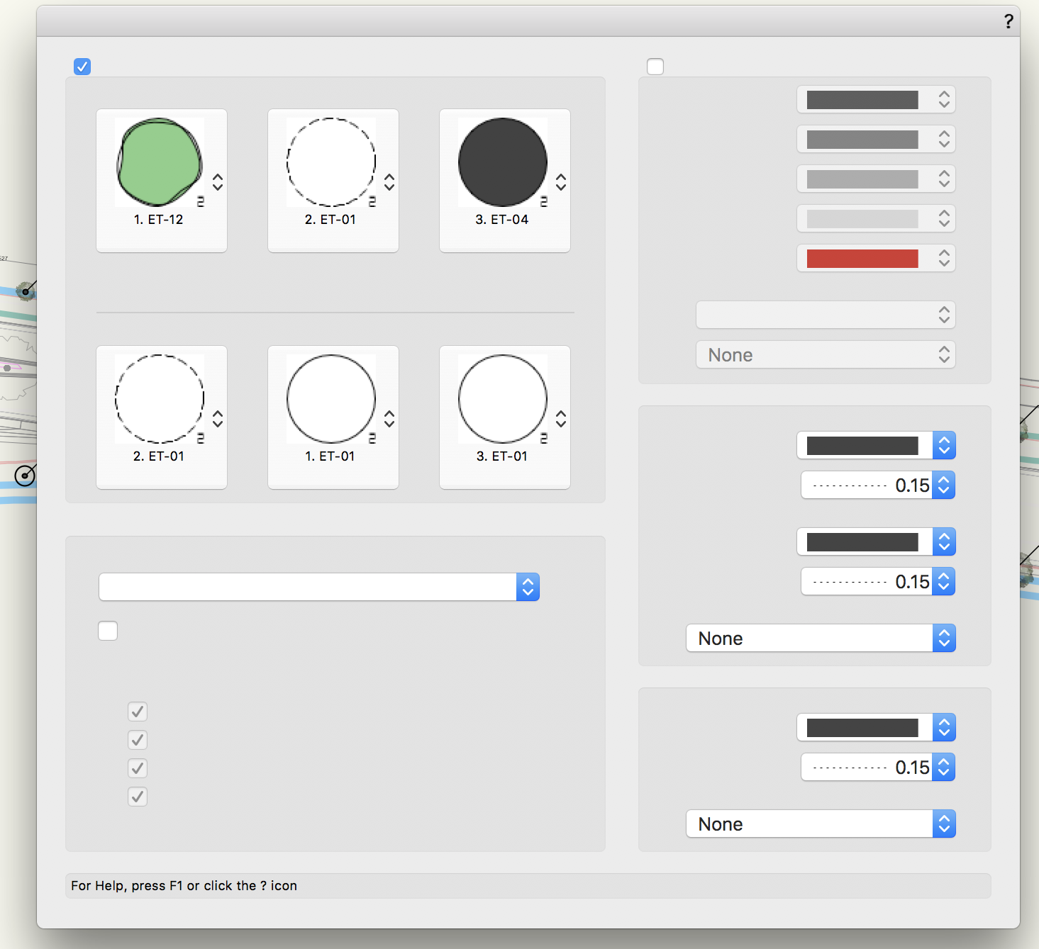
We have a new issue, never encountered prior to VW2018. Currently we are having difficulty with Plant plug-in object visibilities...I've attached 2 screenshot videos (no narration, sorry) that show what we are encountering, but I will do my best to explain. We have (8) different classes we use to control the internal visibilities of our Plant objects. Currently, these classes are not responding to simple on/off/gray controls unless you go into each plant individually, after changing the visibilities, and then exiting the plant. Then and only then do they look correct. To make things worse, this error is compounded by the fact that as soon as one database worksheet plant schedule is recalculated, all of the active visibilities and buggy visibilities revert to a pre-altered state. I know this isn't the most clear description and I hope the screen captures do it more justice. Ultimately we need this fixed ASAP. This is a bad bug that affects our ability to produce any documents. Plant_Symbol_VW2018_Bugs.mp4 VW2018 Plant Bug 2.mp4