Search the Community
Showing results for tags 'landmark'.
-
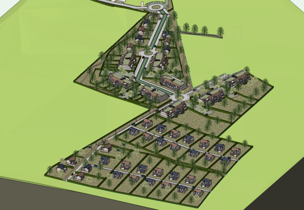
Hello, How do you guys manage your workflow withou making your Vectorworks files bulky. In the exemple below i have use reference for my buildings and house. My files have reach 600MB and i am yet to create viewport for presentation and print. The file contains vehicles, people, Road pol light, Hardscape for the road and land, Wall styles was use to create the hedge, 3D trees and 3D site modelling. Thanks for your advice and help.
-
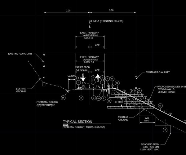
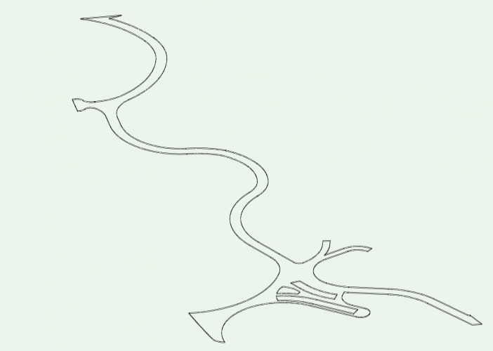
It it possible to createa road on a site model with a complex cross section profile? I have to design a road with a compelx road - gutter - shoulder profile. Look image attached . The examples in VW Land design only offers a road with a simpel square gutter. Any help?
- 1 reply
-
- landmark
- landmark2017
-
(and 3 more)
Tagged with:
-
I would like to request Unit and Labelling for the grade tool similar to the Stake Tool. Units for grading are often not the same as the drawing units. our drawings are usually millimetres and vertical grading units are often metres to conform to the survey units. Also the ability to label a grade is important such as bottom of stair, bottom of curb, etc. Stake has all of these features. We have to double the amount of work in our grading drawings by using the Grade Tool to calculate and show slopes and the use the Stake Tool as a 2D graphic for labelling. Very time consuming.
-
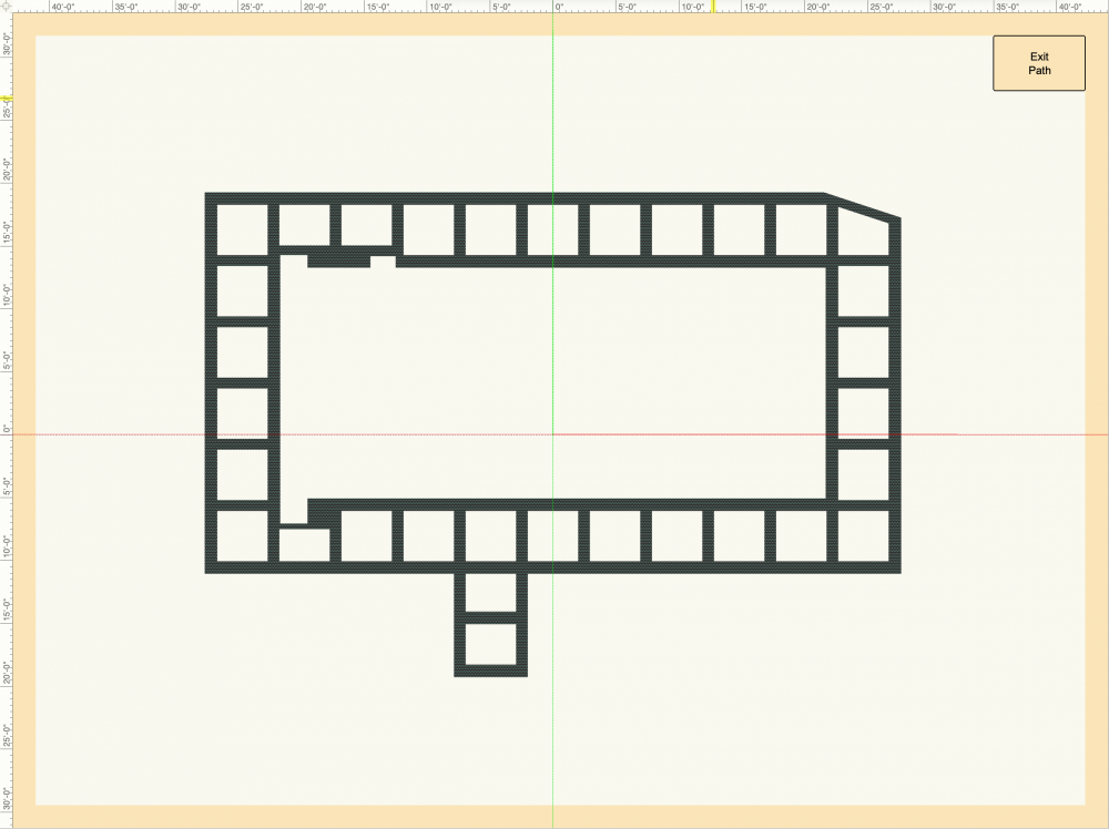
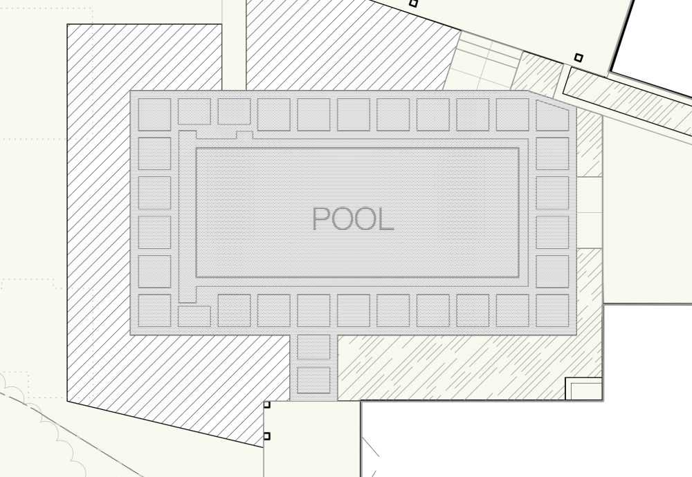
I've been trying to find the solution to this for a while, but I'm not sure if I'm googling the correct terms. I want to make the Borders of Hardscapes more real-world accurate. When I apply a texture to the Border Slab in the Object Info, it visually looks like the rest of the hardscape (i.e. a seamless texture repeated across the plane of the surface). This hasn't been an issue in the past, but we recently showed some renders to a client and they fell in love with how "unique" and "creative" the pattern of the border was, and we had to explain to them how this was just representational and not accurate to what we normally install for borders. I'm struggling to insert URL images to show what I mean so here are some hyperlinks instead: How the paver border looks in Plan View Render shown to Client An example of the look we're trying to achieve Is there a specific setting somewhere to make Renderworks textures align to curves and look how they're supposed to, or some workaround? I'm working in Vectorworks Landmark 2023 SP6 (Build 711238) (64-Bit) Thank you!
- 3 replies
-
- landmark
- landmark2023
-
(and 3 more)
Tagged with:
-
Assign class to a plant
James Dawson Design posted a question in Wishlist - Feature and Content Requests
Hi, I would love to be able to place a plant and it automatically assigns to a class, regardless of the current class setting. -
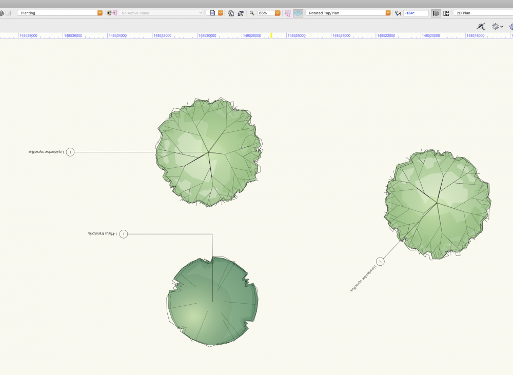
Help please, I am finding it impossible to insert plants onto a rotated plan and get the tags to behave. Desperate to know how to resolve this asap. This plan is rotated -134. The tag text is upside down, whichever way i rotate it. I have tried inserting plants to an unrotated view, but as soon as I rotate to a view that would work on a sheet layer... upside down and all over the place.
-
I am working in VW 2023 and there is one plant symbol that won't show up in the schedule. It is on the correct class and layer (same as all other plants) and I have tried duplicating it as advised by someone in another post having the same problem. Any idea why this is the case?
-
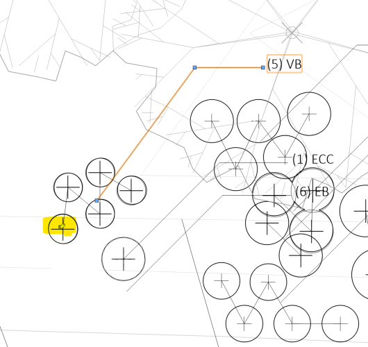
I would like the ability to choose "insertion point" or "center" for auto placement. As it is a data tag seems to attach to the center of the object (when using the "all eligible object mode" at least). It would be nice to have a setting to snap to center of object OR snap to insertion point - especially with grouped objects, like multiple plants combined into a single plant object. Currently with grouped plant objects I have to repoint EVERY data tag to the proper place. Screen grab showing auto-placement and current insertion point: I don't see an option for this on any of the data tag style tabs - but it does seem like it should be on the "auto placement" tab. In all honesty I would like to have the ability to auto select the start or end of the grouped plant object - but that's a completely different wish. grouped plants need some tweaking...
-
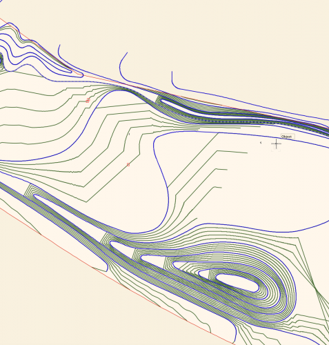
I'm wondering if I'm missing something in terms of the control we have over site modelling in Vectorworks. I've attached a screengrab of a site model I have created. Blue lines are the 3D polyline contours I have drawn and set to 0.5m height intervals, the green lines are the contour lines generated by the site model calculation by Vectorworks, using my blue lines as input data. I have two big issues with this output, namely: I want the model to EVENLY interpolate between the contour lines - for example on the hill to the bottom of the screen grab, I want the mounding to extend evenly to the left, I don't want flat platforms between each level. I want the contours to actually follow the curves I have drawn, and not truncate my contours in large angular lines!! (As seen in the middle of the screengrab.) Is there anything I can do, aside from draw contours at really tight intervals to reduce the visibility of the problem? Is this just how the site modelling algorithm works? I understand the need for a mathematical algorithm, but this results in a fundamentally incorrect site model I can't really use for anything in terms of BIM or production information, as it isn't giving me smooth grades. I'm sure I could fudge it for visualisation purposes, but I need an accurate technical model I can issue in IFC form to provide information for collaboration and also construction. I've turned on mesh smoothing in document properties, which makes the rendered model appear slightly less angular, and also turned on contour smoothing display, but I need an accurate model in terms of BIM compliance and I'm not sure I have this control outwith doing an excessive amount of contour drawing. Is Vectorworks the wrong software for this, or am I missing something? Any ideas or advice would be much appreciated. Lisa
- 21 replies
-
- site design
- site model
-
(and 3 more)
Tagged with:
-
I have a site model if a area alone the water front. I am set contour data for areas on the water to be below 0 (negative levels) I will like this surfaces site model to render blue color to allow clearly differentiate between upland and wetland. Here is a link to the VW file https://www.dropbox.com/s/ro2ke5nzk1dqqh0/Hacienda_Delfines.vwx?dl=0
-
Is there a way to turn off the automatic irrigation network update that occurs at every pipe connection? The disruption to workflow with having to wait 5-10 seconds after every single lateral pipe placement is getting to be quite tedious on larger irrigation plans. I cannot find any setting to disable this feature. I would much prefer to lay out the lateral lines of a zone and calculate the pipes after I have everything laid out. I do not know if this is an issue with my personal workflow, which is as follows (short version): 1. POC Setup 2. Mainline Run 3. Design Zones 3. Head Placement 4. Lateral Line Placement 5. Valve Cluster Placement Should I be approaching my irrigation drafting in a different order? Can I just turn off calculations until I am ready for them? Thank you.
-
We're seeking an experienced Vectorworks ‘Landmark’ designer/drafter starting on an as-needed/contract basis to build to a long term position. This position is preferably filled by someone in Ontario OR has working knowledge of regional and Municipal building, planting and permitting requirements. Typical duties include: Creation of Site Plans with Site measurement and documentation Grading design Planting and Lighting design Creation of site models, Shade Shadow Studies Production of Planning and Construction Drawings Your skills should include: Vectorworks Landmark 3D and 2D drafting Preparation of permitting documents Enthusiasm for design and sustainability Ability to work remotely, self-starter, detail-oriented +'s are experience with Sketchup and/or Twinmotion rendering skills Uncommon Ground Design Group Inc., is a small firm focused on high-end custom landscape design in the Province of Ontario, Canada Email: design@uncommonground.ca
-
- employment
- landmark
-
(and 3 more)
Tagged with:
-

Gradient Cut Fill Site Model Visualization
ericjhberg posted a question in Wishlist - Feature and Content Requests
It would be awesome if you could generate a 2-dimensional visualization of a Site Model's cut/fill, but instead of just static Cut = Red and Fill = Blue...you could assign a gradient for each that could color the site model based on cut severity or fill severity. For example a White to Red gradient for cut that the greater the value of cut, the deeper the shade of red. Additionally a White to Blue for fill that the greater the value of fill, the deeper the shade of blue. This would be an extremely useful way to visualize site models. @Tony Kostreski @Eric Gilbey, PLA @Vlado @bgoff- 4 replies
-
- 4
-

-
- site model
- landmark
-
(and 2 more)
Tagged with:
-
I am trying to streamline the documentation process for designed plant communities for both installation and visualizing with clients (along with my own forgetfulness). I have a resource drawing that I keep for plant objects with records attached that describes the varying interest season-to-season. I am experimenting with pulling these object styles for use with landscape areas, then using data visualization to show floral, foliage interest for a given season. This works with individual plants but not plants nested inside a landscape area style. Do landscape area styles retain records for plant styles attached to them? If so, should they show up in a data visualization with the records attached? I will try to clean up a test drawing and post on Monday. Cheers PWF
-
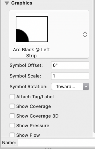
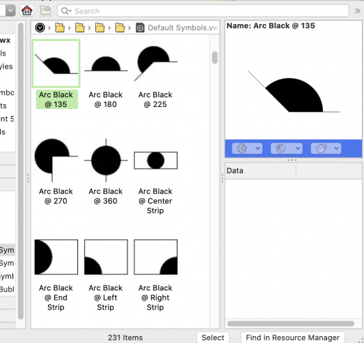
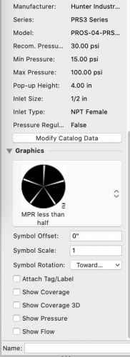
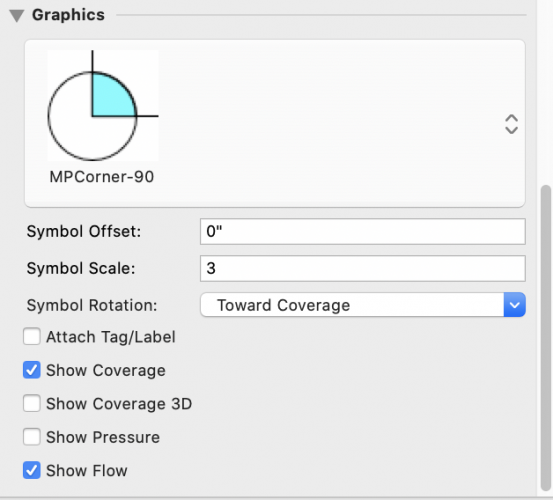
Anyone know how to apply the correct symbol for irrigation heads (get it to "stick")? When I pick the correct symbol (1/3 head, standard vectorworks symbol, filled), vectorworks picks a different, wrong symbol (Q head, unfilled). Luckily, the catalog data remains the same. Replacing with a custom symbol works, but it does not rotate correctly, cannot be manually rotated. Or maybe it can, but I don't know what to include in my symbol to create a properly rotating symbol, nor show how to specify the direction to the center of the spray pattern, nor basically anything I'd need to make this work. Workaround (bad): create a custom symbol that does not show arc so if it doesn't rotate, no big deal. Not a great solution, but better than quarter heads for half pattern! OI Palette was my compromise so I could continue working. Yes, I really did want the symbol in "wanted.png"! FIRST IMAGE: Vectorworks (wrong) pick SECOND IMAGE: WHAT I WANTED: My choice from standard Vectorworks symbols THIRD IMAGE: My crappy compromise that doesn't rotate away from the spray pattern.
- 3 replies
-
- landmark 2021
- landmark
-
(and 3 more)
Tagged with:
-
Hello, Im using Vectorworks 2021 SP1 and I just tried to use the VBvisual Plant Tool - More Plants but it gives me an error page and I can't download more plants. Do you know any website where I can download new plants to complete my design? I'll prefer not to use the Plant tool because the Top Plan view is mostly terrible. Best regards, Martina
-
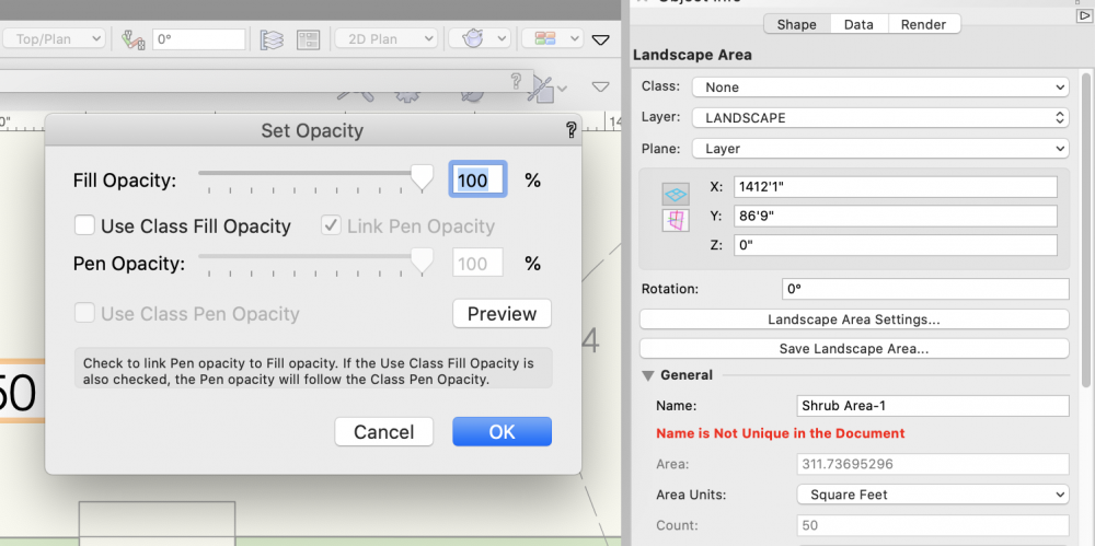
For years, I've been wishing that you could assign different opacities to fill and pen style in a Landscape Area. You can do this with most other objects, but not a landscape area. It would make life a lot simpler as I like drafting with a more transparent fill, while having the pen set to 100%. Basically, I just want to be able to uncheck the "Link Pen Opacity" box in the "Set Opacity" palette.
- 3 replies
-
- 7
-

-
- site design
- landmark
-
(and 3 more)
Tagged with:
-
Shut up and take my money!!!
jpccrodrigues posted a question in Wishlist - Feature and Content Requests
https://paper.dropbox.com/doc/Land-Kit-BETA-R9DujKA3zEYp69LBbOjbq Talking about logarithmic design, this is the direction that VW should look at!!! Really makes me consider start learning a new software https://tse2.mm.bing.net/th?id=OGC.ec3def206059f4eae13c2385248ab72b&pid=Api&rurl=https%3a%2f%2fmedia.giphy.com%2fmedia%2f1AhNXmfWcHnfq%2fgiphy.gif&ehk=pFLrEQLMUvjQm0dyb4U7RFvNbT8549QxTAx3T6VJr0w%3d -

Landmark Drip outlet modification CRASH CRASH CRASH
Luciole Design posted a question in Troubleshooting
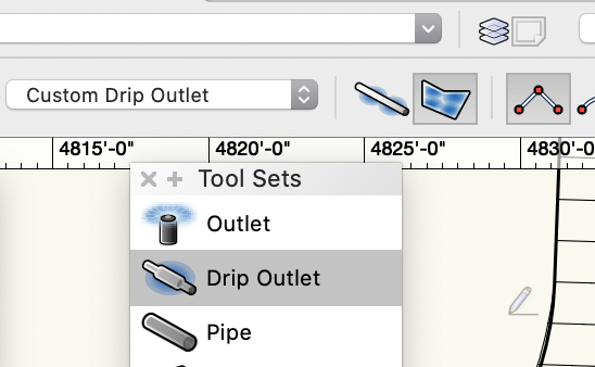
Vectorworks 2021 is crashing about every third time I move the connection point or adjust drip line emitter direction. As per your tutorial, I'm adjusting the drip line before connecting it to a valve. Sometimes deleting the drip polygon and redrawing helps, but the crashes still continue. Most often it's a "beach ball of death forever" freeze, but sometimes it's Flash! Gone! No Vectorworks. Restarted computer. Still crashes. iMac 27" retina 2017, 40 GB RAM, Vectorworks Landmark 2021. Mac OS 10.15.7.- 13 replies
-

Irrigation Outlet - Problem with Symbol Rotation
loretta.at.large posted a question in Troubleshooting
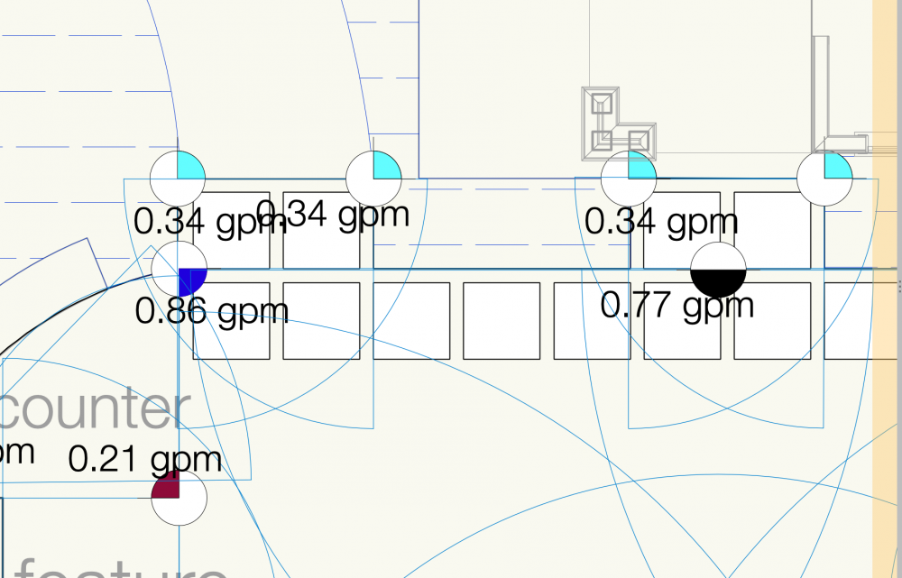
I'm working on an irrigation plan and decided to make a new symbol to use for an irrigation Outlet because I wanted the graphic to have a different color. It seemed to work at first, but when I rotate the direction of the spray, the symbol doesn't rotate with it like it does with my other irrigation outlet objects. All I did was duplicate one of the existing outlet symbols I had in the Resource Manager, changed the color, and gave it a different name.... but it just won't rotate! I also have "Toward Coverage" selected where it says "Symbol Rotation" in the Object Info Palette on all the outlets. Attached are a couple images for clarity. It's a little cluttered, but you can see that the burgundy, black, and dark blue symbols point in the same direction as the coverage, whereas the light blue symbols do not rotate with the coverage direction. Am I doing something wrong? Or is this a bug in the program? -
When doing a large irrigation system (I'm working on several with over 70 stations), the connection time is incredibly cumbersome and slow. The file I am currently working on takes up to 15 seconds to make one connection. Additionally, we have already turned off the Auto Calculation Update feature, so that is just processing time. Some simple math to show you how cumbersome this actually is... 830 outlets of just one type (over 2000 total in the project) = 830 connections 830 connections at 15 seconds each = 12,450 seconds = 207.5 minutes = approximately 3.5 hours of drafting to make the connections. When compared to our traditional methods, we could do this drafting in approximately 1 hour or less. So for 2.5 extra hours, what do I get? Some data attached to the pipe network? That would be great, except half the time there is at least 1 error for every 20 outlets, which has to be found, diagnosed, and corrected, adding at least another hour to the mix. I get that we are supposed to be moving into the "smarter, not harder" category, but this is only coming at it from the "smarter" perspective while making it a whole lot harder to meet your targets. Expand your horizons Landmark and start thinking bigger than a single, lot residential project. We need BIG applications here that scale easily!
- 8 replies
-
- 5
-

-
- irrigation
- landmark
-
(and 2 more)
Tagged with:
-

Hydrozone Tool - Negative Space
loretta.at.large posted a question in Wishlist - Feature and Content Requests
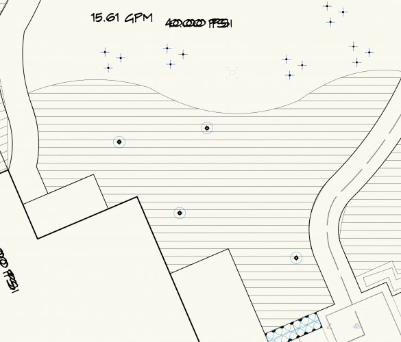
I find the Hydrozone tool to be very useful for MWELO calcs and for irrigation plans. However, I sometimes find the tool cumbersome to use. One request is how Hydrozones graphically display when there is a hole or negative space in the center of the polygon (or path object). The area seems to calculate properly, but I don't like how it looks like the hydrozone areas overlap in places it's not supposed to. Here are screenshots so you can see what I mean. -
I use landmark and use additional plant records to include information about landscape areas such as seed mixes which then input into my schedules (worksheets). As these detailed soft and hard landscape drawings can get very heavy on larger sites (very painful for my work flow), I would like to split up the drawings into seperate files (eg. soft, hard, specific designed spaces) which I then reference as viewports into a drawing with the sheet layers and worksheets. This helps for a number of people to work on the project at once by splitting up the drawings in this way. This works well until I come to schedule the drawings and the records are not imported although landscape areas and plants are. Currently I have to combine my colleagues drawings before scheduling which is very time consuming and usually crashes. It seems sensible that all data is available from referenced viewports.
- 2 replies
-
- landmark
- landscape area
-
(and 2 more)
Tagged with:
-
I've created a hardscape by boundary, due to varying width and form - though the hardscape is essentially intended to be a path, and I need to treat it as such in terms of levels. I know using the roadway / pathway settings you can edit each point on the path to set the level and crossfall... is there a way to do this with a boundary hardscape? Essentially I want to be able to input the edge levels along the route in 3D, and then potentially make this a modifier for my site model. Is the workflow for this to edit a base site model, placing stakes at the required chainages, and then set the hardscape as a texture bed only? I'd ideally like to set the levels within the hardscape itself, and keen to use the slab settings within the hardscape to allow detail sections. Any help much appreciated.
-
In VW2019 and now in VW2020, after the new creation of Plant Styles, there is a problem with the way the Plant Tool operates... Upon picking a precisely defined Plant Style to use with the Plant Tool, the tool does not have the ability to place the plants using the Style Definition for Spread, Height, or Spacing. This means that when plants are placed using the tool, they automatically are placed using a custom Spread, Height, or Spacing. This may or may not match the Style Definition, but that is a mere coincidence. The only way to make a plant placement respond to the Style Definition for Spread, Height and Spacing is by first placing plants and then by going into the Advanced Plant Settings, Size Tab, and switching from Custom Spread, Custom Height, and Custom Spacing to Use Plant Style. This is a SEVERE regression and a problem with current workflows. Instead please allow for the ability in the Plant Tool Preferences to utilize the Plant Definitions Spread, Height, and Spacing as a DEFAULT. @Bryan G.@Tony Kostreski @Eric Gilbey, PLA @Vladislav Stanev


