
Search the Community
Showing results for tags 'connectcad'.
-
When moving a 3D rack with rack frames to a different design layer, the equipment moves out of the rack frame or the rack frame moves. Therefore making you have to redrag the equipment back into the frames. Rack Frame Test.vwx
-
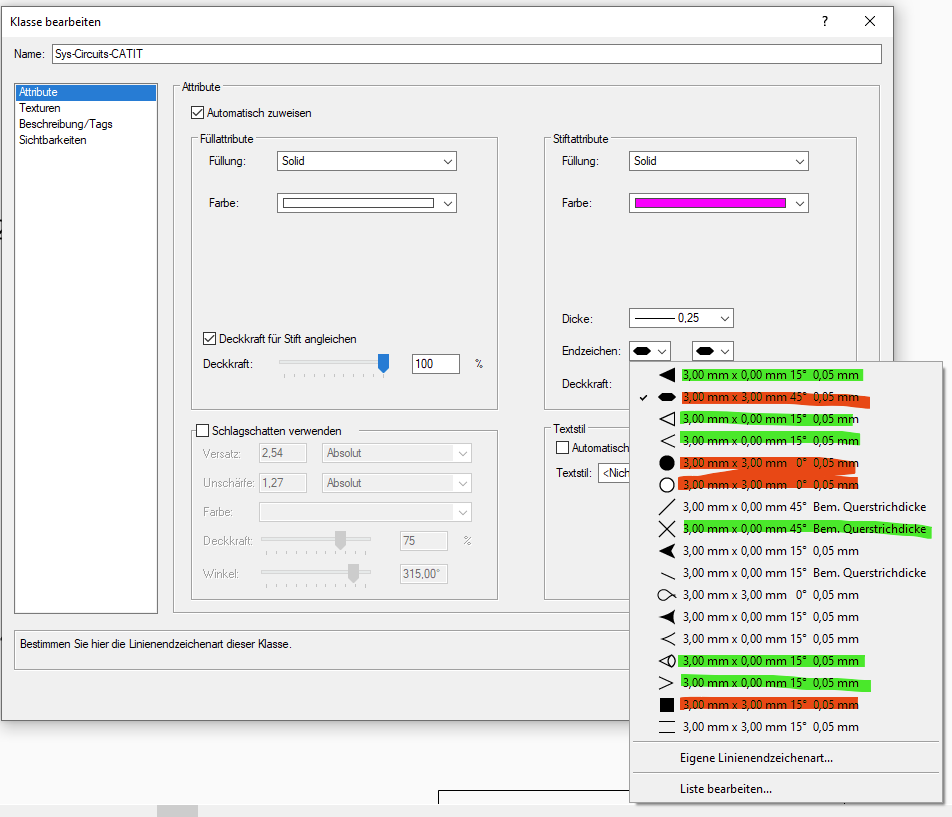
If I change the Text Style for Sys-CircuitNumbers I have to nudge every single cable for this change to be visible. Is there another way to update all circuits when I change the text style for circuits?
-
since it is causing me trouble again: may I add another "tiny" future/feature request? 😬 In another post @Nikolay Zhelyazkov mentioned that the circuit description (for arrow circuits) is limited to a select number of data elements for source and end device. a bit of context: in my current case, I am trying to reference the room of a device which is stored in a custom user field instead of having to place every device in a room in the rack elevation view) unless I missed another option (can't put it in device name or tag): any chance that these will be extended? not sure, what part of the programming requires a limit, but maybe the user data fields could be added? (where anything could be stored via the data manager) thanks a lot, george
-
As I am working on the rack elevations new questions start popping up. Like general questions regarding the way rack elevations can be drawn in ConnectCAD. here's some feedback/ feature request: As many of our clients are used to getting detailed rack elevations showing line drawings of front and back of almost all rack equipemnt, it would be very useful if all rack equipment could really be represented by a symbol as well. Currently this only works for regular equipment (RackU 5,6) and for single cards (Slots 1 and 3 in RU9), but not for rack frames (and possibly for the actual rack). Hope, there is still some space on the team's issue tracker. best, george

-
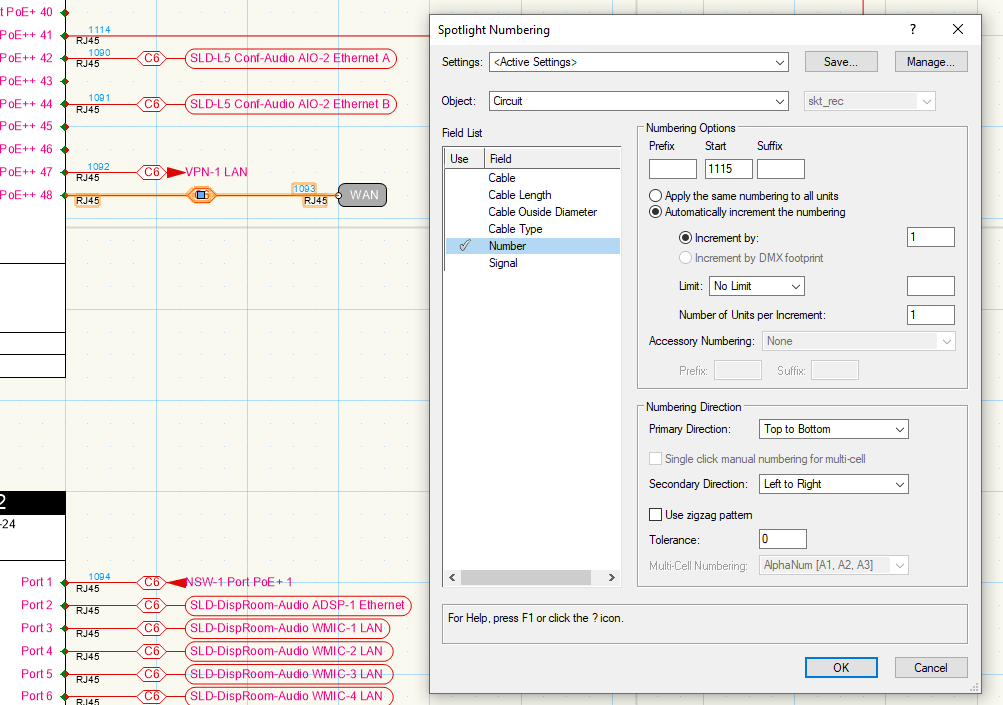
 I am used to using spotlight numbering for connections within a design layer and I remember being able to use it to number connections between design layers. When I use spotlight numbering for connections in between design layers, it does not properly recall a connection's "Circuit" object where you would select the "Number" field to increment. Instead the connection object reports as a "Object with Record" that lacks the fields required to number the cable. I am on the latest version of VW. Any ideas on where the issue lies? Thank you
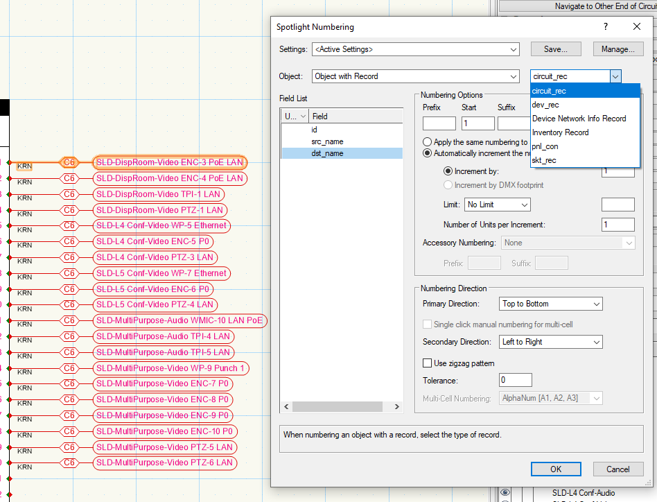

-
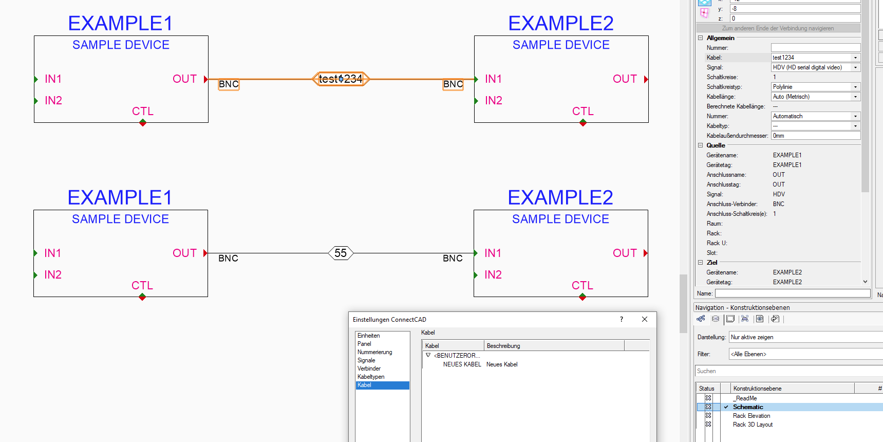
hi guys, not sure how, but my CableOptions.txt file is empty. All my entries are gone. Which I only realised because the dropdown was missing next to "Kabel" (obviously "Cable [option, I guess]"). Just last week I noticed cable options in my dropdown list not being listed in the CC Settings dialog. Guess it has to do of how the dropdown list is created? As I can manually enter values (see below) and when adding a value via the settings dialogue the manually entered values (e.g. test1234) are also listed in the dropdown but obviously not in the settings. gues the initial error had to do with me editing the CableOptions.txt outside of VW. Although it was working fine for the last days. And I didn't do any edits.Is there any posibilty to make these config files more robust? But please don't just answer "Don't edit outside of VW". 😉 (Editing these things inside VW takes ages.) Thanks, George


-
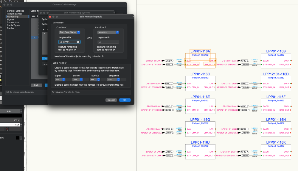
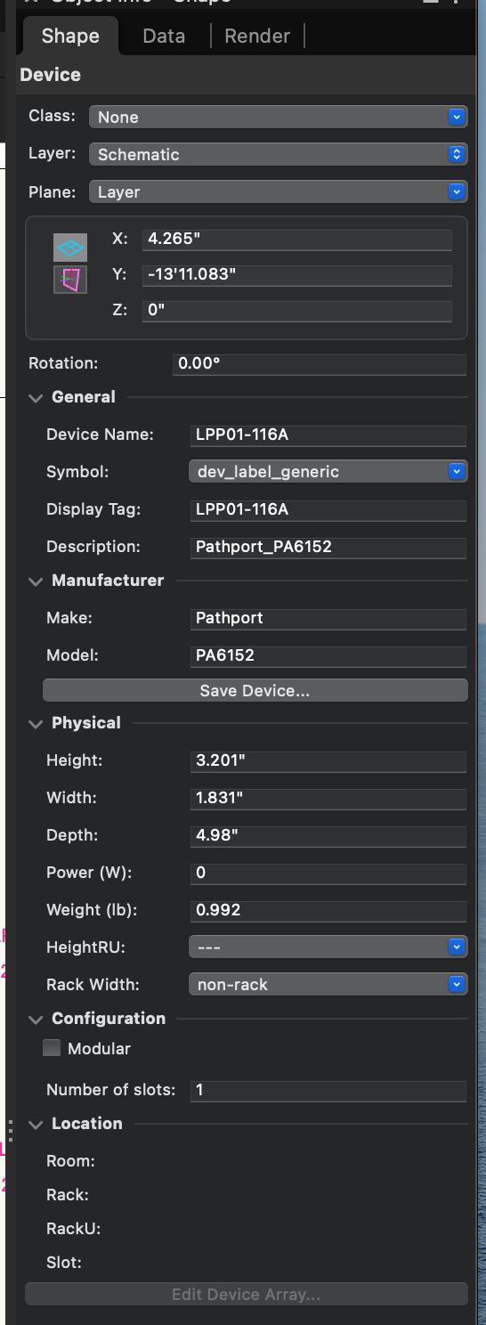
I am having issues with ConnectCAD numbering recognizing device names. I have the destination device name set as my condition but it doesn't see any of them. Have y'all had any luck with the numbering tools? At this point it's almost more trouble than its worth in my opinion. The end goal is to label cables based on plate names. IE: LAN on plate LPP01-116A would have a label of 116A-LN01. (LN = Lighting Network) ETH DMX on plate LPP01-116A would have a label of 116A-LX01 (LX Lighting DMX)
-
I would like to have different symbols for different types of signals (arrow for unidirectional, diamond for I/O connections). And maybe even depending on wether the "jump" leaves the room or not. Is there a reason why I can't use all available symbols?
-
sorry, another bug I wanted to ask about: I don't have admin privileges on my CAD machine and I can edit all ConnectCAD settings except for the numbering systems. Everytime I exit the settings dialogue an error message appears warning me, that the changes to the numbering system weren't saved. Tested it with admin privileges and it worked fine. But as I said I usually don't have those. Company policy. Asking our administrator every time I want to make a change is not really an option. It's already strange to require admin privileges for an VW update, but I can live with that. But setting changes within the software should be available to everybody?
-
 Hello, when I use the "Create devices from worksheet" function from a list with devices that already have unique device names with a running number at the end, ConnectCAD cuts off that last number and replaces it with a space for the first and then its own running number for every following devices. the tool itself is fantastic. but unfortunately this behaviour is slowing me down a lot as I have to rename every device again. My workaround is add a space at the end of the device name in my excel list and after the device was created replace the space in the name via copy-paste from excel to a temporary worksheet to the database list in question (because of this bug). This is what ConnectCAD does... e.g. Excel List: Device-1 Device-2 Device-3 is turned into: Device- Device- 1 Device- 2
 -
not sure about a clear pattern, but when I move devices that have external signals (EXT) connected to them, (some?) connections are lost/disconnected (00:13). And the undo (CTRL-Z) function can't correct it. Neither does Tools>Reload PIOs. I have to reload the backup file. (FYI: I am using these external signals as temporary devices when cables at the other end are not connected yet.) As I can't send my project file I tried to get the same error in a new file, but I guess it has to do with file size or amount of connections/ layers? (Question on the side out of curiosity: Has ConnectCAD been used for "large scale systems"? (e.g. a broadcast station, OB Van or 500 bed hotel?) Main problem is, that I might see the error, when it's already to late and there are 3 file saves and a few hours of work in between. 😕 VW_MovingEXT-Error_A.mov
-
hello, to save time, I am copy-pasting equipment from room to room or within a room and then bulk-update the device name with the find and replace function. so far so good. unfortunatelly linked equipment (espcacially rack location, in-rack position and slot number) is not updated accordingly. Updating PIO (Extras>Intelligente Objekte aktualisieren // Tools>Update POI) does not work either. So I have to go to the OIP of each device, change the name to something non existing, confirm and then change it to the correct device/equipment name. ...not really the time-saver I was hoping for. 😉 am I missing something? thanks, george
-
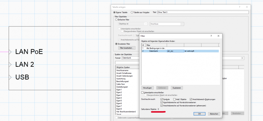
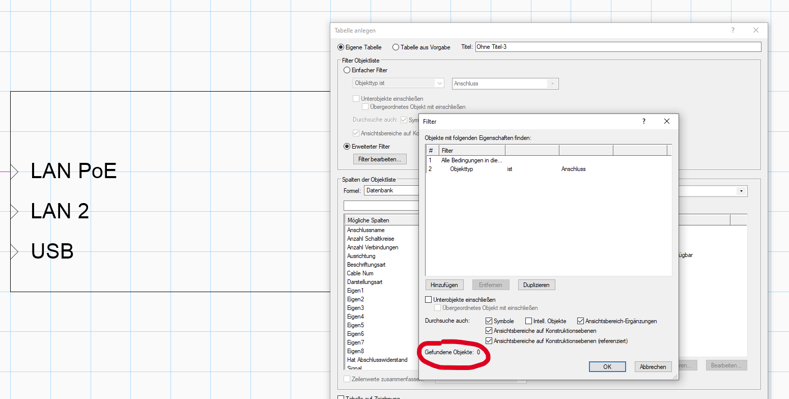
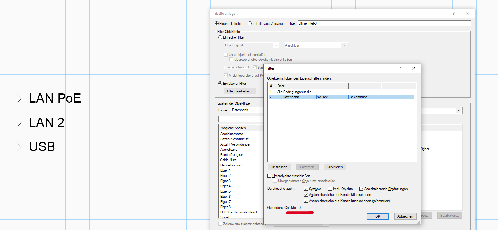
was trying to get a list of all devices in my file, so I could check if they are all up to date with the socket names/count. but whatever worksheet I am trying to create, the PIO "Anschluss" (german for socket) won't show up. But where is their data stored if not in the database "Anschluss"... or skt_rec? sorry, as I mentioned before, I just don't understand how all the databases and ConnectCAD work together (when I have more time I'll have to create some sort of UML overview of all the depenencies... after learning about how to UML. unless you have something like that already @Conrad Preen 😉 ) best, george

-
hello, is it possible to reposition the source/destination flag of a circuit with arrows? Using the reshape tool didn't work. I would like to have the bottom flag in the same position as the upper one without having to use a termination panel (which we don't use in this case) thanks, george (sorry, if this question has been asked before. couldn't find anything. but in that case a link to the post or the help page would be great too. 🙂 )

-
 Hi all, 'Simple feature request'... When creating equipment from selected devices, could the command confirm that there are already some devices selected and pre check the box? Saves a click every time 😉 This feature is already saving me time when allocating equipment to different locations. and the device names ar enumerically different so near impossible to tell which one goes where quickly. I am applying lots of locations for a PA/VA system and assigning the speakers to zones. all 30 of them, so having to repeate the create equipment command over and over, and place only those devices into Room Locations (zones). Cheers, R
 -
Hi All, Getting to grips with VW/CC'22 and liking some of the new features 🙂 Well done all! Looking for recommendations on how best to document circuits that have been deliberately left un/disconnected, (e.g. a cable that has been pulled out of a patch panel) but could be reconnected later. Or a cable installed in readiness for future requirements. I have used <EXTERNAL>s so far but notice that the connected end of the cable shows the name '<EXT>' as the device name plus the External Name, in my case "NOT CONNECTED". Any tips welcome. Thanks, R
-
Hello! I don't know if anyone is encountering this issue. But for some reason ConnectCAD won't undo properly. If I move a device accidentally sometimes the connector doesn't move with it but it doesn't show as disconnected either, and if I hit Undo it will undo the information but won't reposition the devices back to their original state. Yet if I try to manually move them back to where they were, the connectors would adjust and mess up my whole organization. It gets a little frustrating and sometimes it ends up crashing my entire laptop too. I don't really know if there is a solution to this. I have tried restarting the file, and restarting my computer, it no longer crashes but it still won't undo properly. Thank you!
-
Hi Guys, Not entirely sure how they got created, but I had a number of yellow triangular warning symbols dotted around a schematic the other day I selected the circuit lines which I thought they were associated with and tried to work out why they were highlighted. On clicking just the warning symbol I was able to delete it (and the offending associated circuit) so I am guessing that some how the circuit was zero length. I realise you have a lot on and we are all eagerly anticipating great things this summer (no pressure! 🙂 ) but, could you include this as a consideration to check for zero (or silly short) length circuits in the check drawing function or something? Thanks as always, Ross
-
Hi all, I am getting used to using save views and love them! On a similar thread to a feature request I put in a while back regarding viewport layer visibility in saved views.... Are there any plans to include snap settings as one of the elements that is saved within in a saved view? For example,jumping between a layout view and ConnectCAD schematic can be a bit cumbersome having to switch from grid snap only on and most, if not all others on each time. There have been a few occasions where a non-grid snap has caused problems in schematic view - but thank goodness for snap to grid tool to bring it back in line (ctrl+ - ) Cheers, R
- 3 replies
-
- 1
-

-
- connectcad
- snap settings
- (and 1 more)
-
ConnectCAD Default Circuit Type
Ross McLee posted a question in Wishlist - Feature and Content Requests
Hi Guys, Nice feature request... When defining a socket on a device, could it include a default circuit type?... "curved, chamfered, polyline arrow etc" This would speed up having to change between types when connecting some devices which are more suited to being remote and needing an arrow, to those situated next to each other which would be best served with a line. Just a thought! Cheers, Ross -
Hi again, Another feature request! Would it be possible to create viewports from a schematic layer by selecting the items you want to include in the viewport and click create viewport (I have a shortcut CTRL+SHIFT+V). This would be instead of having to create a rectangle and then using that as the crop border. It may require a degree of crop 'margin' )say one or two grid squares or may be a %age of the length/width to give some space around the objects being cropped nicely, and the viewport laying on the sheet layer centred 🙂 But this would speed things up nicely !! Thanks as always, R
-
Hi, One for @Conrad Pand Co.... Would it be possible to add a URL field to the Device symbol definition (and perhaps others) which you can populate with a link to the manufacturer's data sheet or website perhaps?... Might be handy when creating reports to link to the website for further information, installation manuals etc.. Cheers, R
-
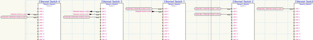
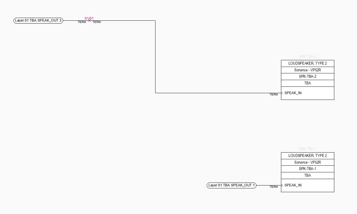
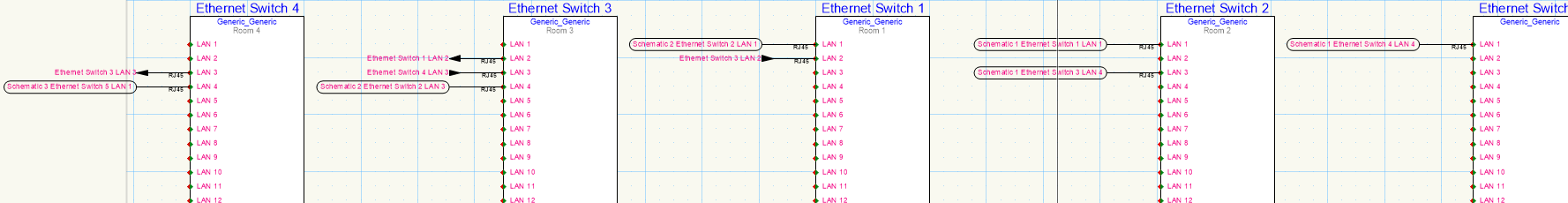
Hi again, Finding my way around ConnectCAD a little more comfortably. Q: When connecting two sockets using the arrow connector type OR when connecting two sockets across two layers. Is it possible to customise what the circuit label displays? It would be particularly handy for example if the label said the destination room or rack. When a circuit crosses between two layers, displaying the layer names is not particularly helpful (especially if they are simply called schematic 1 and schematic 2). I suppose I could change the devices to be more descriptive of the location, but would prefer to automate it through the location: room or even rack properties. Example of all the variants I have come across so far, attached. Note: Show all layers is on, so you can see all three layers clearly. Thanks as always, R
-
- 1
-
-
- connectcad
- circuit
- (and 2 more)
-
Hi, New to ConnectCAD - I was wondering what the best practices are for making RF connections in ConnectCAD schematics. Showing them accurately/correctly in the schematic and perhaps scheduling channel assignments. I am looking at using arrow connector types. With diversity I have A and B antenna but only showing connections to A for the moment. Just wondering what people recommend and anything to look out for. Help always appreciated. Ross
-
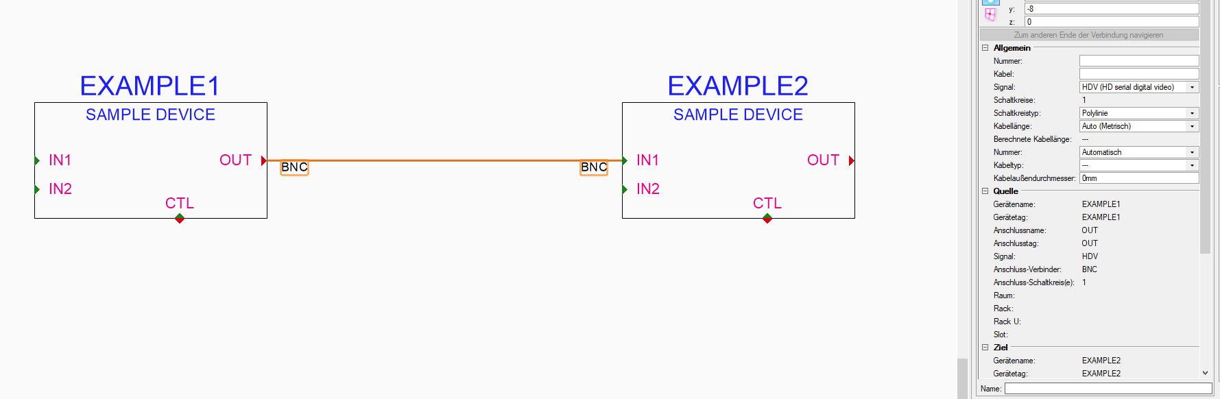
Feedback. Minor issue doesn't impact use. But I noticed when copying a device (ctrl+mouse click and drag) that the indicative outline of the device as I moved the mouse, included the arrow connectors which the source device had connected. I panicked the first time .. but on releasing the mouse button the device copied as it should, the outline just confused me for a moment I thought had selected everything - not just the device on its own). I guess this is mimicking move behaviour , not copy. In the attached screen grab I couldn't keep the CTRL key depressed and take a snap shot (so you can't see the + sign mouse pointer) R
.thumb.png.ecc1f3c88c98192e5b0f1ed598302d56.png)


.png.c9044077cc7af8712b47326d77907810.png)