Search the Community
Showing results for tags 'bim'.
-
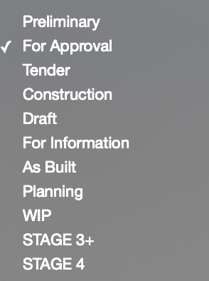
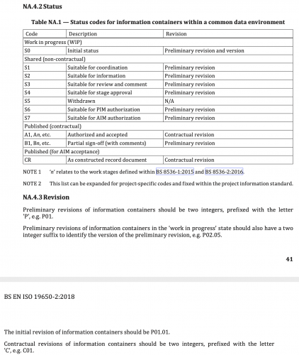
Below are two screenshots. One of some traditional drawing status notes of old. And next to it is ISO 19650 BIM status/suitability codes and descriptions (from the UK National Annex). I find some of the ISO suitability codes and processes a little confusing, particularly regarding work in progress. Any thoughts? Work in progress S0 - Initial Status - as I understand it this is only for internal use only, when editing your model/drawings, and should never appear on models/drawings shared with the rest of the design team. ISO 19650 explicitly states that information in the work in progress state/folder shouldn't be accessible to other task teams. But we often need to discuss work in progress with other team members so how are we meant to issue WIP information to other design team members if no one else has access to our work in progress folder? Should we instead be issuing in the Shared folder with S2 Suitable for Information, as below? If so then what revision code should be used? If it's work in progress then it's meant to have a revision code with a two-integer suffix (e.g. P01.01) but ISO 19650 UK Annex states (NA.4.3 Revision) that this kind of revision code is for work in the Work in Progress folder/state. Which no one else has access to.... Shared (non-contractual) S1 - Suitable for Co-ordination - I find it a little odd that the first status code is 'for co-ordination' when we would typically issue information 'for comment' or 'for approval' before we issue 'for co-ordination'. S2 - Suitable for Information - simple enough I guess, but no explanation in the ISO 19650 UK Annex defining it accurately. S3 - Suitable for Review and Comment - see comment above on S1 S4 - Suitable for Stage Approval - what is a "stage"? Can it mean any self-defined stage (e.g. "layout approval" stage). Or does it mean RIBA Work Stages? Or does it simply mean this is suitable for final approval before moving to a 'for construction' status? S6 - Suitable for PIM (project information model) Authorisation - straightforward, information that's ready to be authorised for management of the construction project S7 - Suitable for AIM (asset information model) Authorisation - straightforward, information that's ready to be authorised for asset management of the project Published (contractural) A1, etc - Authorised and accepted - straightforward, approved and accepted information for construction B1, etc - Partial sign-off (with comments) - straightforward, good way of revising 'for construction' information Published (for AIM acceptance) CR - As constructed record document - straightforward, 'as built'

-
Hi guys, I've been using Vectoworks Landmark since 2017 and, at this moment, I use it as my exclusive software. Each project that I develop with Vectorworks I try to enhance the BIM capabilities of the software (IFC import, water budget, plant schedule, etc.). After seeing the webinar with Eric Berg, I saw that I have a long path to walk... The questions that I would like present are: Do you reccomend a specific online course? Last year I did one about Sustainable Site Design / Analysis and helped me a lot. Do get to a "smart design", I saw a lot of custom spreadsheets. Are they done with the normal spreadsheets or are you using other resources? Can you give your feedback to "step up the game" and use all the resources that VW offers? Thanks!!
-
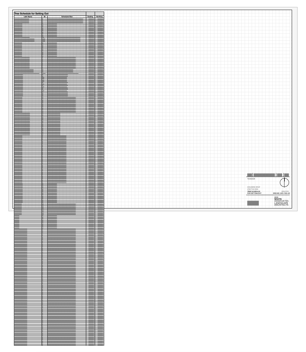
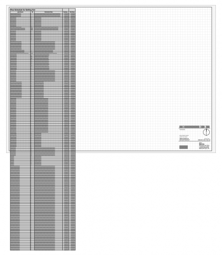
I have a reeeeeeally long worksheet generated from a load of data in my drawing. I want to display the whole thing on a sheet, but because there is so much information it doesn't fit on the page, and as such I want to split the worksheet (probably a couple of times, and ideally with the headers repeating!) so that I can fit all the info on one page neatly. I also want to still be able to recalculate the worksheet. Is this possible?
-
Hi all, I am still fairly new to VW working with a new practice, with a background in ArchiCAD. Currently the drawing templates are split into 3 separate models: Concept Planning Construction In ArchiCAD, the use of "renovation filters" allowed all work to take place in one model, assigning elements of the building to different stages of the project. Does VW provide any similar function? Thanks in advance.
-
Hi everyone. I am fairly new to VW with previous software experience mainly in ArchiCAD. I am working for a practice and we've discussed having multiple users in a single file/model working at the same time. Now, in ArchiCAD there is a Reserve and release method, where you can research elements of the model to draw, and request to use reserved components from other users, where they can than release, freeing it up to use. Does VW offer a similar method, to allow for multiple users to work from the same file at the same time? Thanks in advance
-
Hi, Can anyone help with importing IFC files into vectorworks?...First I imported the IFC file and then converted it in to an Auto Hybrid, then to 2D/3D symbol to give the object the 2D Visual I want. However when doing this process the IFC (BIM) data is hidden?..or disappears from the object.. Is there a way to add the BIM data so it is seen on the 2D/3D symbol?. Thanks
-
 In addition to the Land8 Social Media Awards honor earlier this year, global design and BIM software solutions provider Vectorworks, Inc. proudly announces that it is a winner of two awards from BUILD Magazine: their 2019 Design & Build Awards’ “One to Watch in 2019” and “Best BIM Software Developer 2019 – Metro Washington D.C.” in the Home & Garden Awards. Additionally, Vectorworks was touted as one of the “Leading Providers of BIM & CAD Design Software 2019” in the 2019 Designer Awards, hosted by LUX-Life Magazine. “It’s a tremendous feeling for Vectorworks to receive its fourth award this early in the year,” said Jeremy Powell, VP of marketing at Vectorworks. “I would like to thank BUILD Magazine and LUX-Life for these prestigious honors. It keeps us motivated and focused on providing a one-of-a-kind software program for the design community.” The BUILD Awards are dedicated to uncovering and rewarding the very best in technical innovation, design and service. This program showcases companies around the world that are innovating, trailblazing and deserving of recognition. “Here at BUILD, we noticed that Vectorworks had a fantastic 2018, and we believe they will go on to do great things in 2019,” said Megan Cashmore, features executive at BUILD Magazine. “With the release of their 2019 software, we have seen a huge increase in efficiency and innovation for designers within the industry. Their success has led them to be selected as a One to Watch in 2019.” Along with BUILD Magazine’s 2019 Design & Build Awards, Vectorworks has also been selected as the “Best BIM Software Developer 2019 – Metro Washington D.C.” in their 2019 Home & Garden Awards. From creative minds in landscaping and interior design, to cleaners and carpenters, this award is designed to highlight companies supporting professionals to truly make a house a home. And last, but not least, Vectorworks has been crowned as the “Leading Providers of BIM & CAD Software – 2019” in the 2019 Designer Awards, hosted by LUX-Life Magazine. The Designer Awards reward the innovative and those who exceed the public’s expectations year upon year to provide an excellent selection of new products and experiences for the everyday consumer. “The 2019 Designer Awards prides itself in identifying outstanding work in a field which provides so much, not just to the economy, but society as well,” said Jessie Wilson, awards executive at LUX-Life. “Receiving such an accolade represents that all of Vectorworks’ hard work, dedication and creativity is truly paying off!”
-
- 1
-

-
- build magazine
- lux-life magazine
- (and 3 more)
-
How detailed can BIM go? Maybe it's because I use Vectorworks for product design, and we model everything in 3D to precise detail, which forms the basis for manufacturing and assembly drawings, but I find the BIM components restrictive and low on detail. Maybe this is the point? That the BIM model is a 'diagram' and not the real thing, appropriate for 1:20 scale but not particularly detailed at 1:2? Do I need to work within the simplistic representations of BIM components, and the configurable settings on offer, in order to benefit from their functionality? Or can I push the detail further? And how is the best way to achieve this? For example, on a simple panelled door, I can't add chamfered beading to the panels on the leaf settings. On a top hung casement window, I can't add a rebate and have the opening window further out than the fixed glazing below. I can't seem to edit the BIM components to what they actually are in reality. Do I need to change my mindset - that this isn't reality?! Do I need to adjust my thinking of what BIM is - an intelligent model, with elements which are 'generic representations' - or can refine and add detail to my hearts content, and what is the best way of doing this? Can BIM be as flexible as 3D modelling, or is this just 3D modelling and BIM is something else?!
-
Hi, I am looking to add BIM to the 3D symbols which I've created in Vectorworks. Could anyone point me in the right direction to accomplish this? Thanks
-
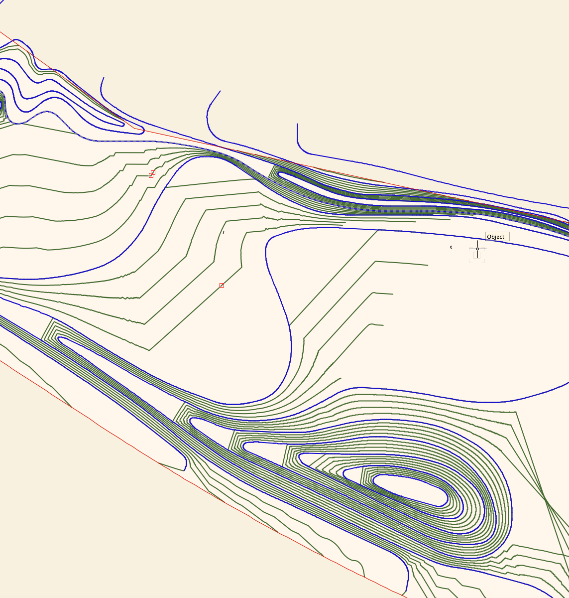
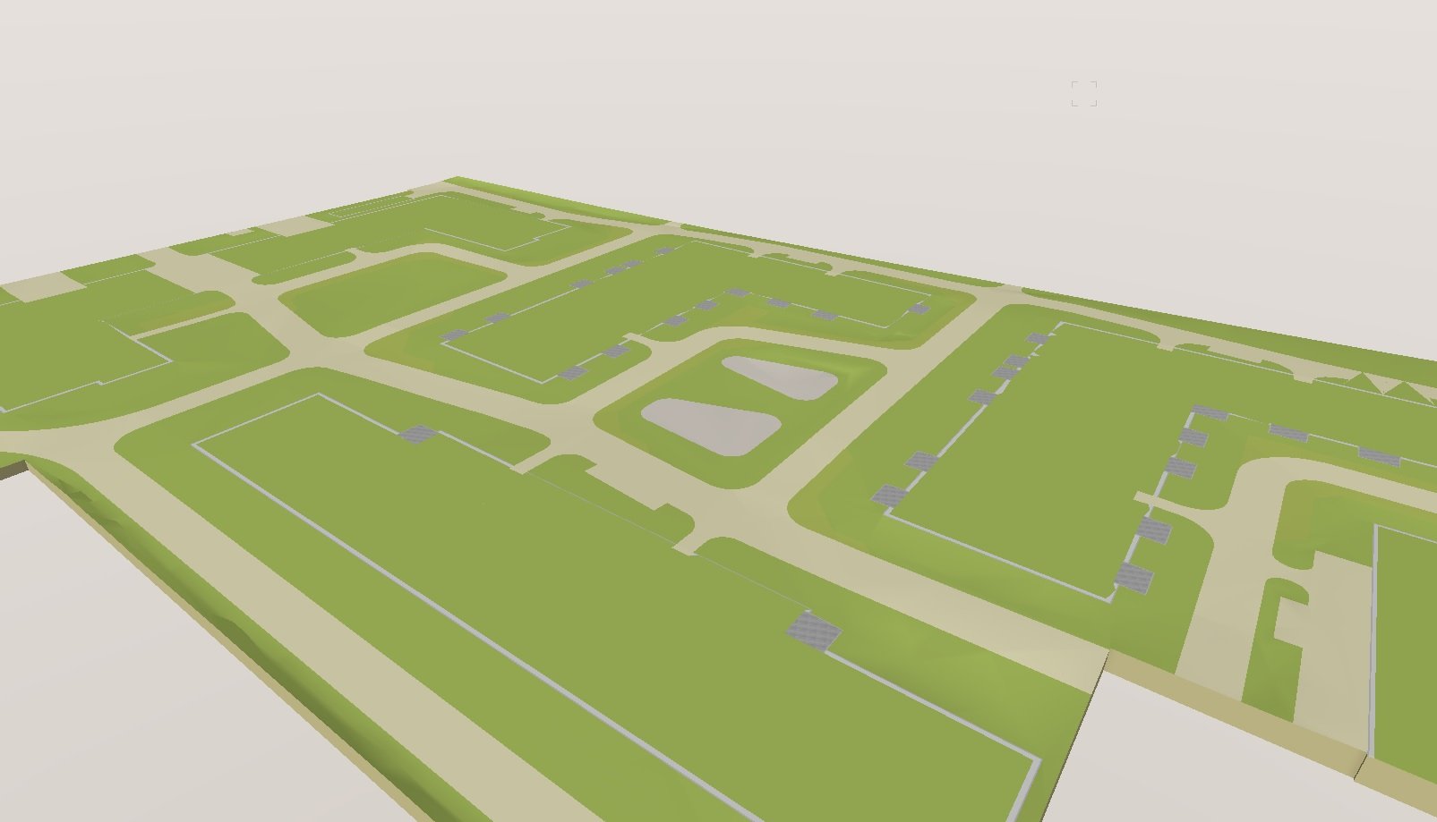
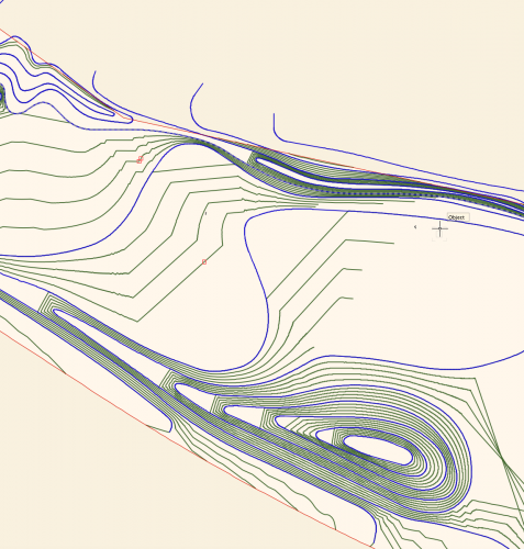
I'm wondering if I'm missing something in terms of the control we have over site modelling in Vectorworks. I've attached a screengrab of a site model I have created. Blue lines are the 3D polyline contours I have drawn and set to 0.5m height intervals, the green lines are the contour lines generated by the site model calculation by Vectorworks, using my blue lines as input data. I have two big issues with this output, namely: I want the model to EVENLY interpolate between the contour lines - for example on the hill to the bottom of the screen grab, I want the mounding to extend evenly to the left, I don't want flat platforms between each level. I want the contours to actually follow the curves I have drawn, and not truncate my contours in large angular lines!! (As seen in the middle of the screengrab.) Is there anything I can do, aside from draw contours at really tight intervals to reduce the visibility of the problem? Is this just how the site modelling algorithm works? I understand the need for a mathematical algorithm, but this results in a fundamentally incorrect site model I can't really use for anything in terms of BIM or production information, as it isn't giving me smooth grades. I'm sure I could fudge it for visualisation purposes, but I need an accurate technical model I can issue in IFC form to provide information for collaboration and also construction. I've turned on mesh smoothing in document properties, which makes the rendered model appear slightly less angular, and also turned on contour smoothing display, but I need an accurate model in terms of BIM compliance and I'm not sure I have this control outwith doing an excessive amount of contour drawing. Is Vectorworks the wrong software for this, or am I missing something? Any ideas or advice would be much appreciated. Lisa
-
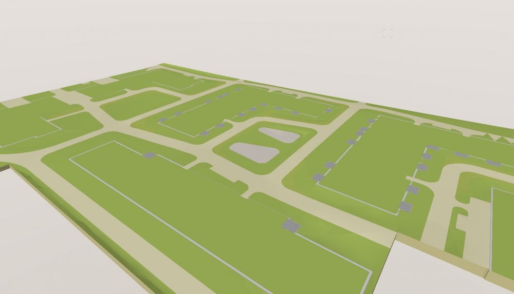
Hey there, is there a workaround to extract the texture pads on a site model for further use? I cloud imagine to generate solids via marionette from the 3D polygons (for BIM use). I know it is possible to have a 3D hardscape, but with serious drainage planning i can't get what i want. Cheers...
-
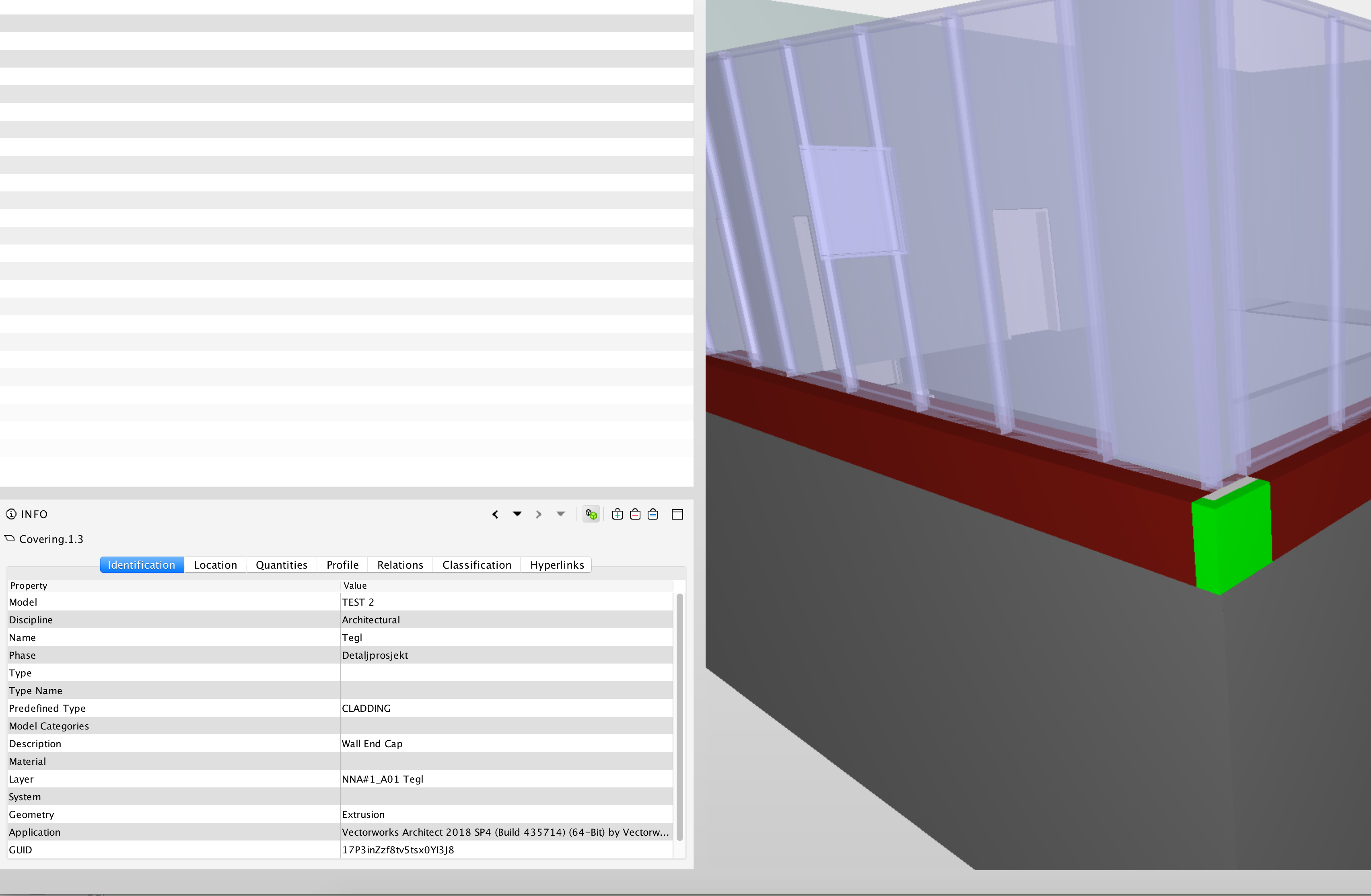
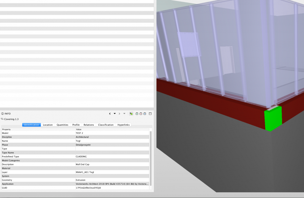
Hi, Before we have had issues with the wall end cap to IFC. It has exported as "open sheets and not a solide wall into IFC. Then we did a work around to make it solide. In 2018 SP4 it export as solide, but its not a wall it export as covering not wall that is an issue for us. Is this fixed in 2019 or will there be another service pack on 2018?
-
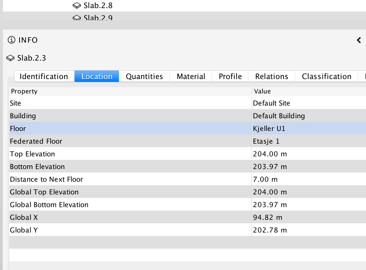
Hi, There is a new feature in Solibri in the INFO Location pallet called Federated Floor. I have done a couple of exports and don't understand how I can control this from Vectorworks to IFC. Seems like its random. Does anybody know how to control this from VW?

-
 I'll be teaching a 2-day hands-on Vectorworks BIM workshop at the AIA offices in Santa Fe, New Mexico, USA, on October 12 and 13: https://www.eventbrite.com/e/santa-fe-vectorworks-bim-workshop-tickets-50280749074
 -
To best support and grow its rapidly expanding user base, global design and BIM software solutions provider Vectorworks, Inc. has opened a new corporate office in Canada. To facilitate this new office, Vectorworks has acquired Resolve Software Solutions and the assets of Paxar Technologies Corp, both long-time distributors of Vectorworks software. The Vectorworks Canada office is located in Vancouver and led by Geoff McBeath, former director of Resolve Software Solutions, who has more than 20 years of experience in Vectorworks support, training and sales. “The opening of a Vectorworks office in Canada will allow us to better serve our growing community of users in North America, offering improved resources and a direct connection with our product development team,” said Vectorworks CEO Dr. Biplab Sarkar. “Geoff McBeath has provided significant contributions to the growth of this market over the past two decades, and he and his team will continue to offer training and support to designers in the AEC, landscape and entertainment design industries.” “I am very pleased to be joining Vectorworks, a company with which we’ve had a close relationship over many years,” said McBeath. “For Canadian customers, I think this an excellent development — it says that Vectorworks considers Canada an important market that has strong potential for growth, and that it needs to be served by a Canadian team that understands local concerns. With a larger staff and the resources of Vectorworks headquarters behind us, we are poised for strong growth in the coming years.” The Vectorworks Canada office is located at 207 West Hastings Street, Suite 611, Vancouver, BC, V6B 1H7. In addition to the office in Vancouver, Vectorworks plans to open a satellite office in Toronto. Qualified sales candidates in Toronto are invited to explore open positions. More information about Vectorworks can be found at vectorworks.net/ca.
-
- 4
-
-
- resolve software solution
- paxar technologies corp
- (and 3 more)
-
Hi folks, did some one successfully use the wall component function in an ifc-export? Neither ifc 2x3 nor ifc 4 does anything for me. What am I doing wrong? Where is it supposed to be found in an ifc-file? Vectorworks Help doesn't offer anything remotely helpful. Regards, Eddi
-
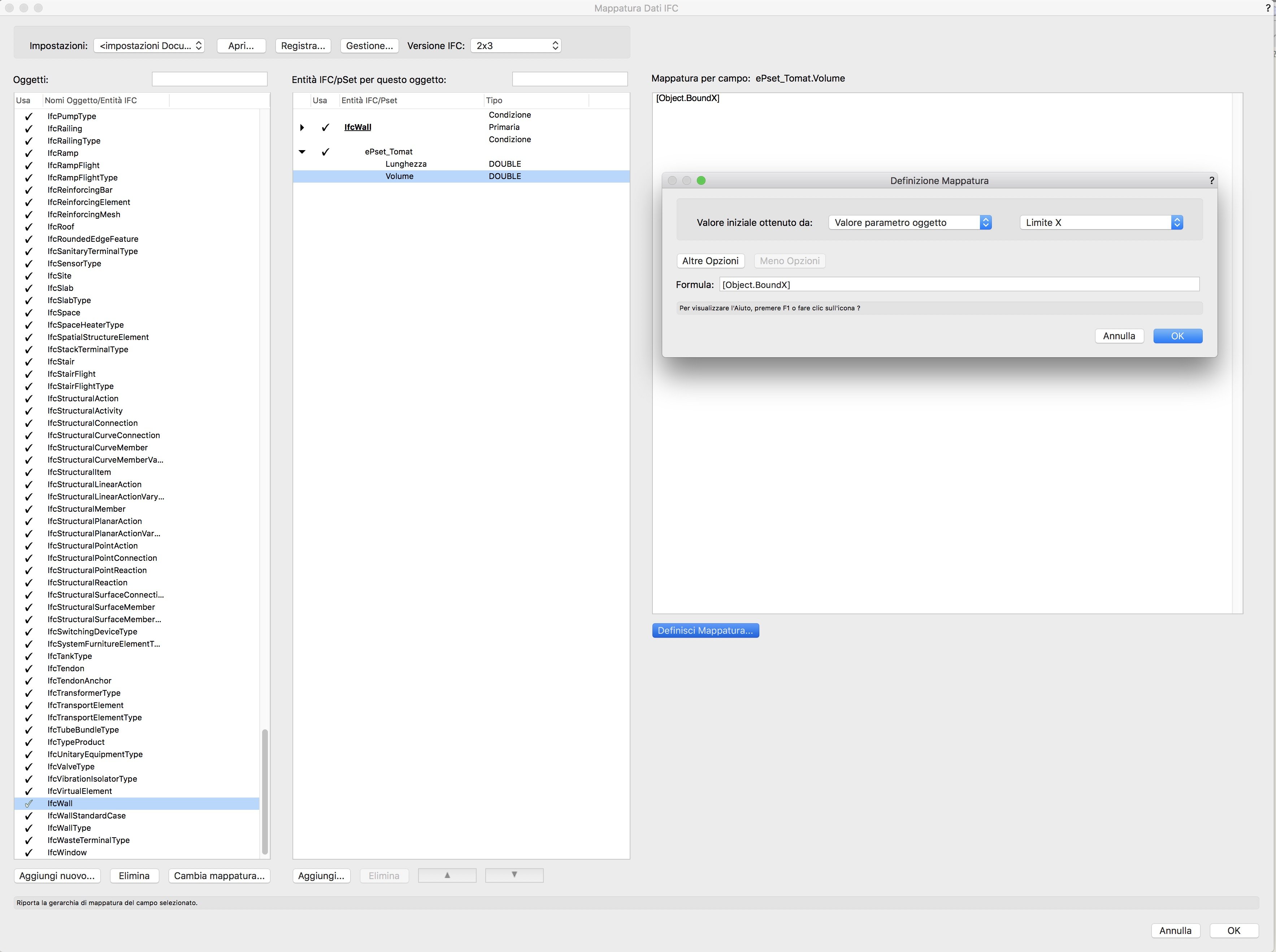
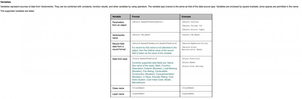
Hello everyone, I'm learning how to manage personal IFC data on specified object. My goal is to generate a IFC file with specified information, to manage costs in STR vision. On this way, I'm trying to set a specified personal pSet, and I'm searching for a variable that can define the object's volume, for instance. Actually I just created the record format to define the fields to fill. I would like to create a variable formula that generate data depending from the object's volume. If I correctly understand, I need to add a specified formula in the pSet dialog into IFC data mapping dialog. After that, I need to manage the specified mapping on the specified voice. The focus is: where can I find the entire formulas list to manage it? For instance, I need to add the volume, so I think it depend from a specified object's variable data. I just find this short list attached: it is the right way?

-
Are there any plans for a complete MEP modeller in the near future?, we need to compete with Archicad and Revit on that specific area.
-
Hello, We are working on a BIM level 2 project and have to import our 3D landscape model (produced in Vectorworks) into the Architects master Revit file. We planned to do this via .ifc but it is not importing in the correct place. If we export our drawing as a 2D .dwg it imports correctly but the .ifc seems to lose its georeferencing. Does anyone have any idea why this might be/if I am missing something? Many thanks! JJ
-
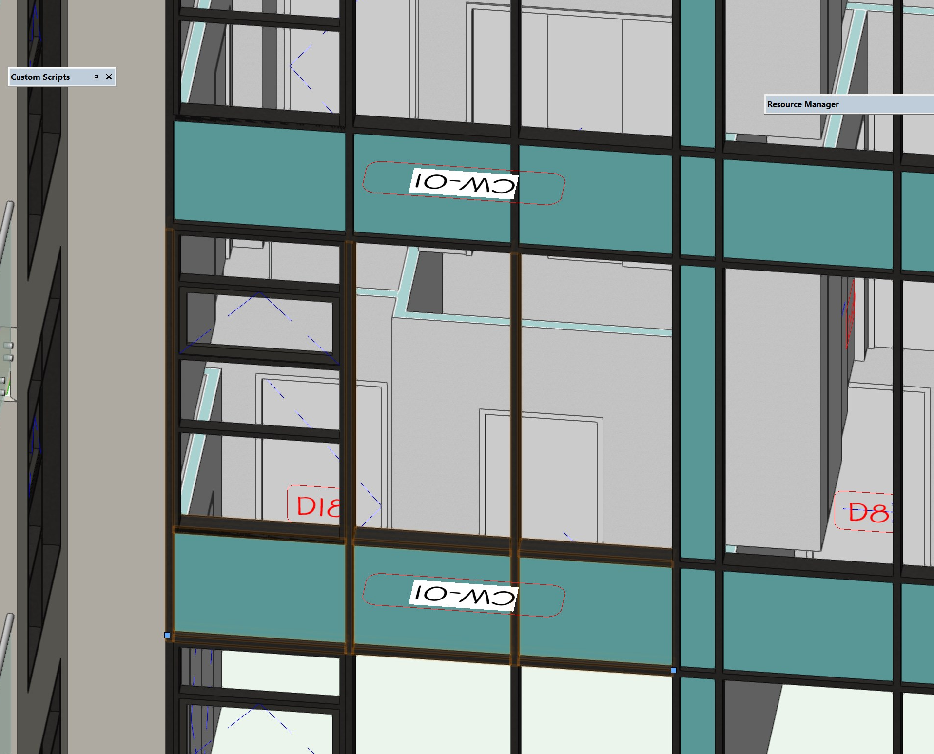
Greetings all, Does anyone know how to get glazing areas from a curtain wall object? And a harder question, how would we query only the glazing (minus the spandrel area)? Possible/Not Possible?

-
I am trying to import a Revit *.rfa file for a product, VW is giving me this error "This version of Revit file is not supported". Does anybody have a solution to this? Thanks
-

Tag/Label Tool has Bigger Ambitions
ericjhberg posted a question in Wishlist - Feature and Content Requests
I may have heard from a little birdie that a broad overhaul of labeling capabilities/tools may be in the works in coming versions. As I have become recently aware, the solution may already be hidden in the irrigation tool suite and it might not need much tweaking to become the full scale labeling tool we need. The Tag/Label Tool within the irrigation tool suite not only has the ability to label irrigation objects with inherent data in a variety of customizable label styles; thanks to @Bryan G. I just learned that the tool can actually represent ANY data attached to objects in plug-in parameters or custom record fields. This is HUGE. In order for this tool to become the tool we need however, there are still a couple of tweaks that would inform an ideal workflow. The Tag/Label, when placed on an object, needs to lock relative to that object. This means that if the tagged object moves, the tag/label moves relative to it. Note that not all labels need to point directly to the object, but in the general direction and this functionality needs to still exist, but in this case, if the tagged object moves, so too should the tag/label move. Ability to save styles and remember most current - When tagging/labeling different objects the style or data labelled might change. There needs to be a way to store these different styles and the ability to choose from them, but also remember the last one used so that it doesn't revert to a default setting each time a label is placed. Act Like Keynotes Placed as Keynote Callouts - Auto-numbering and organization are the primary benefits of using keynote callouts currently and we use them almost excessively considering the difficulties with managing the callout database. This tool has the potential to offer the benefits of that tool without the fuss. If the tag/label chosen has the ability to be represented by a Keynote Callout that puts the label in a Keynote Legend and auto-numbers/letters similar to callouts currently, we could then build extensive keynote legends/worksheets based on objects' inherent data that auto-numbers. Place in Annotations - I imagine that this is perhaps the hardest ask, but it is potentially the most influential...we need the ability to somehow use these Tags/Labels in the Viewport Annotations space while still linking to the objects present in the design layer. It is far easier to organize labels for legibility when placed in the annotations and it removes design layer clutter. Additionally, when placing callouts in Viewport Annotations you can take advantage of the viewports margins and white space to aid in legibility and organization. This isn't something you can do when placing on design layers. Finally rotation...many viewports are rotated and in order to represent labels on these viewports when placing in design layers, you must rotate them to read horizontally...often in very extreme angles which just adds to the clutter, confusion, and chance for error. All in all, this tool is very close to what we need and I am excited to find ways of working it into our workflow. My hope is that VW takes this into consideration when working on any new Tag/Label tool.-
- 3
-
-
- annotations
- bim
- (and 2 more)
-
We work a lot with a building contractor (under DnB contracts) and they've developed their own in-house M&E team. Interestingly they're using Vectorworks, and they've asked if they can have our VW files so they can complete their M&E design. Question is: Do you ever share Vectorworks files and, if so, do you prepare them in any way before sending? It's occurred to me that now we're using Dropbox, one technically possible way to share the model would be via Dropbox + Project Sharing. This would allow us to retain management of the model and restrict the contractor to certain layers. They're entitled to the design under a standard DnB contract but this matter of source files isn't specifically dealt with. I know BIM-tailored contracts deal with these matters so what things do they cover? If I agree to providing them the file, or access to the file, then I imagine I'm going to need to cover issues such as use and limitations, liability and maybe copyright.
-
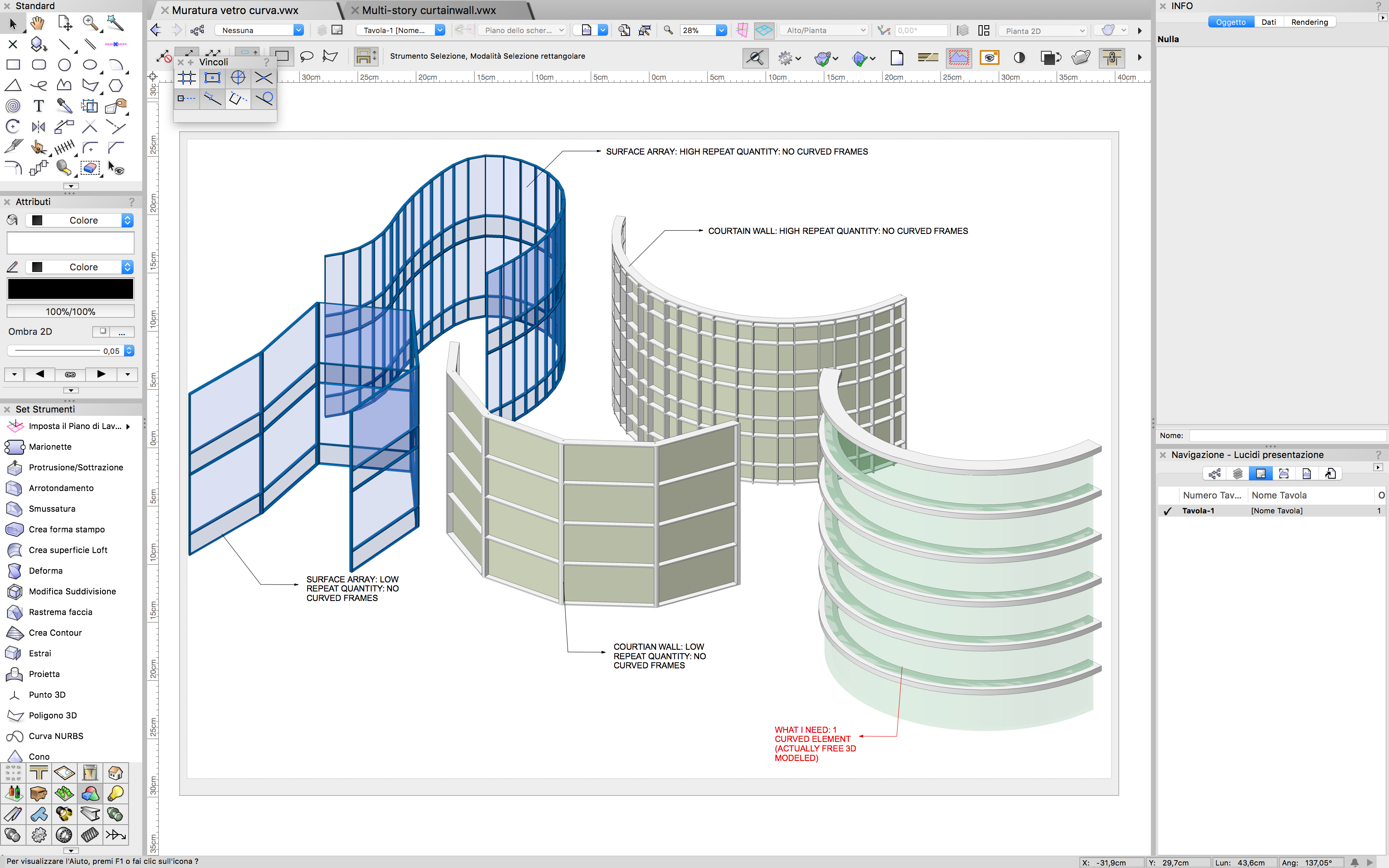
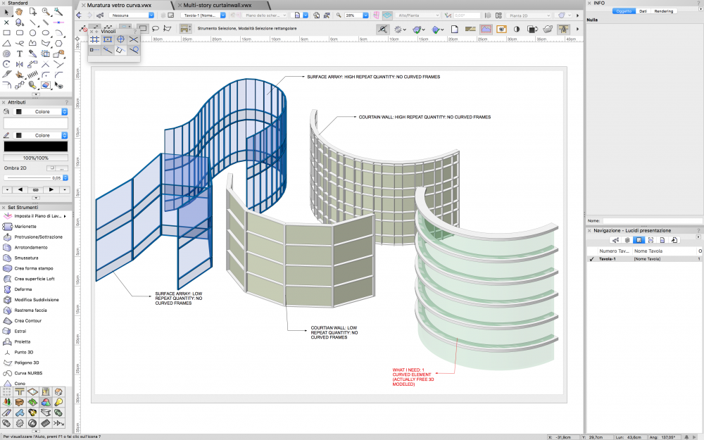
Hello everyone, I need to create a curved curtain wall with curved elements. At first I tried with the surface array tool, but it generate some non-curved elements. Same way with curtain wall tool. I know that theoretically I can manage it with a simple 3D model, but I need to know if it is really the only way. Specifically I need to create a portion of curved wall with few duplication Muratura_vetro_curva.vwx
-
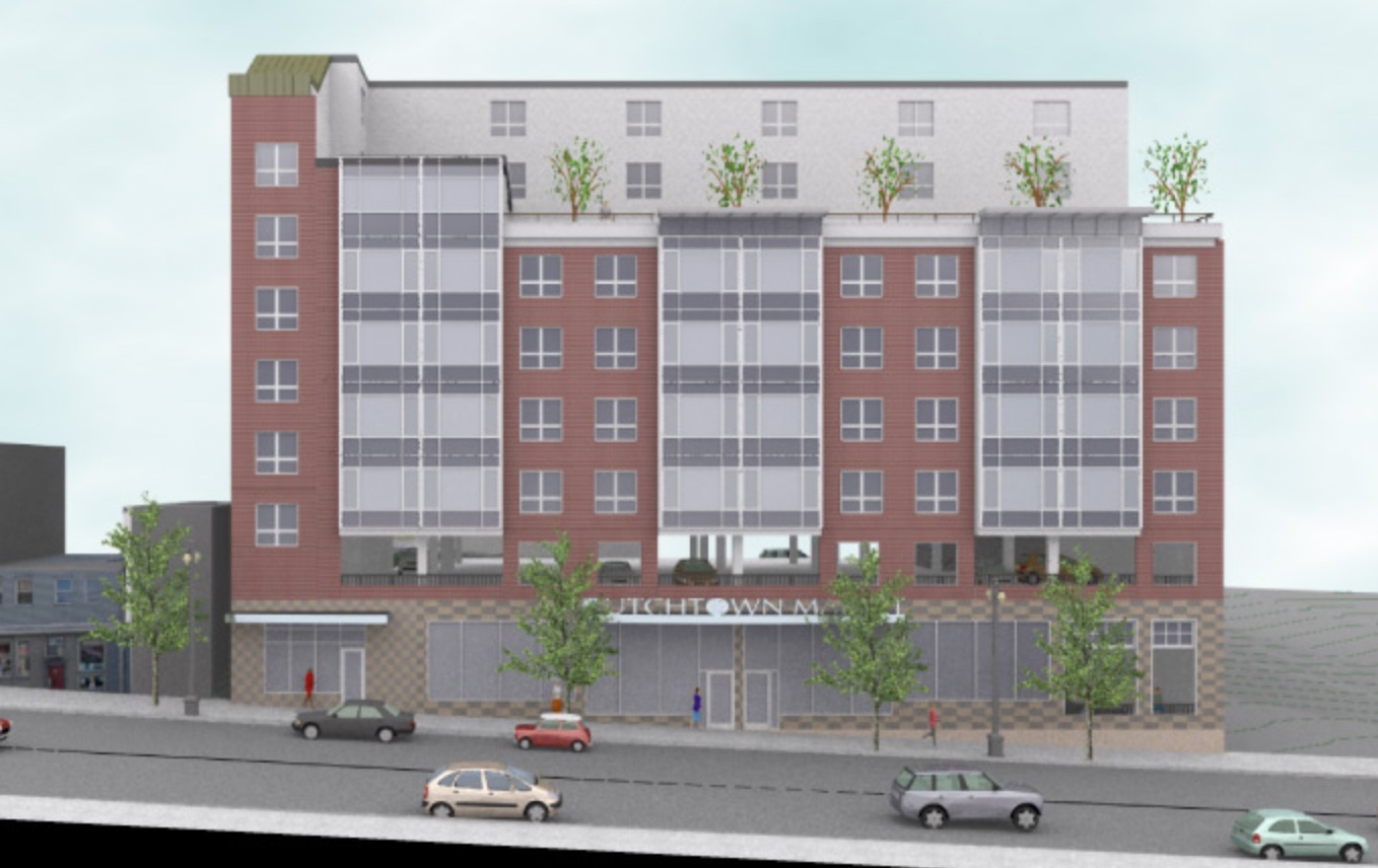
Greetings Something to ponder over the holiday: I have a 7 story mixed use building created in 2010 (i.e. no stories) It was a developed schematic design (all floors modeled, elevations and sections taken and rendered) Many duplicate apartment units which I made into symbols with some strange elevational results but it all held together for what was needed. 7 or 8 years later (now) the project may be coming back to life. I suspect many changes will ensue including story heights. I spoke to VW support and they suggested that I not move to stories due to the complexity of transferring the model layer by layer and the complicated setup. I currently use stories for literally everything (even single story additions, even though levels and walls can be cumbersome at times.) I have found when it works, the results are a real time savings. Anyone have any experience/thoughts/insights on something like this? Steve Steven Glickman Architect 400 Northampton St, Suite 500 Easton, PA 18042 V: 610.253.6536 E: stevenaia@gmail.com http://www.stevenglickmanarchitect.com