


C. Andrew Dunning
-
Posts
1,153 -
Joined
Content Type
Profiles
Forums
Events
Articles
Marionette
Store
Everything posted by C. Andrew Dunning
-
Script to create selection scripts of used Light Instruments
C. Andrew Dunning replied to Tom M.'s topic in Vectorscript
You might find this suite of commands & tools to be helpful: https://autoplotvw.com/. Included are several selection methods. MORE than worth the $...- 8 replies
-
- 3
-

-
- vectorscript
- light instrument
- (and 1 more)
-
While it doesn't contain examples like you suggest, you might find the PDF manual on this page: https://www.landrudesign.com/AudioToolSet.htm to be helpful - especially, regarding the detailed info on the Library and Symbol conventions.
-
@wscooper...
-
Yes and No... The default field contents and the dialog label are one-in-the-same. So..."#" wouldn't be appropriate. -BUT- Changing the defaults/labels to shorter strings works beautifully. So..."Name," "Dept.," and "Change" work. So...the box WILL change dynamically as-desired but its starting-point reference is a function of the DEFAULT string length AND the Dynamic. So...good call!
-
1) This is not what has been said in the past. Other engineers have affirmed that what I am wanting to do is possible - as shown in the other D.T. in the file I posted. The solution in that D.T. is what was suggested by another engineer. 2) Even when I pick one of the 5 fields to use as a single reference - 1 that I assume will be the longest - things still do not work correctly. I tried that before submitting my initial question. I am 100% open to your showing me that working w. a single-field reference...
-
I don't think you are understanding what I'm saying. Yes; the fixed distance constraint IS working - relative to "Department." The desired margin IS 1/8". BUT, Department (and, the other fields) is stretching incorrectly.
-
No; it isn't. Using the image you referenced, Date is the longest. In-theory, the other fields should stretch to match it and the margin should be relative to that stretched width. Instead, "Department" is stretched far beyond what it should be and the margin references that field. - OR - As Date is the longest, the margin should reference that field and the other fields should stretch to fit the margin. Again...the desired outcome is that the right side of the box is constrained to a given distance from the widest field - which could be any of the 5. Look again at the graphic you posted. Date is the widest, but the other 4 fields are stretching beyond its width - for Time, a little and for Department quite a bit - and the margin is referencing the resulting widest field, which is Department. So...the margin might be behaving correctly but the stretching of the 5 fields is not.
-
I believe there might be a bug related to the text block re-sizing. I understand how the alignments are supposed to work but the tool is adding unnecessary spaces. See the instance in the attached file with only "-" in the 3 User-Entered Fields. Compare with the PIO Data-associated fields in the Seating Section label D.T. Change Data Tag - 2.vwx
-
I have a D.T. w. a rectangle bounding box that I want to re-size with data edits (to track a margin w. the longest of 5 fields). So far, in trying different settings, I either get no margins or text fields that expand in unwanted ways. I have a similar D.T. (but, w. only 2 fields) that works as-expected with the same settings. Anyone give me a hint as to what I've missed...? Change Data Tag.vwx
-
Food-for-thought if you want the Class structure saved in your Template: Place an instance of the PIO in-question, change the defaults to suit your wants and get the Class structure in the Parts Classes dialog set the way you want it. Click "OK" an let the PIO generate the Classes. Delete the PIO instance. Re-save your Template. The PIO settings will be saved in a hidden Record and the Classes will be added to your Template structure.
-
Echoing Kevin... In the "Parts Classes..." dialog, you have 2 options: 1) You can set each part Class individually using the pop-up menus - or - 2) You can click the "Assign Default Classes with Prefix," which will set up a default Class structure for you.
-
It really depends on 2 things: How detailed the DWG model is. If the speaker or bumper is tilted once part of the Speaker or Array tool. Highly-detailed and tilted Symbols can REALLY bog VW down.
-
Video Screen info in worksheets
C. Andrew Dunning replied to livespace josha's topic in Entertainment
2 answers: If you use the Landru Design version of the tool, you'll have "Position" and "Unit" fields visible in the OIP for each projector. While not visible in the OIP, projector ID data is stored in 2 hidden fields: "__ProjIDText" and " __Proj2IDText," which can each be displayed in WorkSheets.- 1 reply
-
- 1
-
-
2 things: The line assigned to the "NonPlot-Loci" Class is hard-coded so you can't delete it. The reason the line is so long and the bumper isn't appearing correctly (and, that the speaker isn't drawn correctly) is that the data in the Record attached to the Symbols is not correct. The different dimension fields all must be "Text" fields and must include the correct units marker (like "mm"). Likely, the fields in the Records attached to your symbols contain metric values but VW is treating them as imperial.
-
Here is a file containing a couple of examples. LandruWorkSheets.vwx
-
Like @klinzey said, there is likely incorrect data in the Records attached to the speaker and/or bumper Symbols. If you would post a file containing the Symbols you're using, I'd be happy to take a look.
-
We use a key system based on the last 6 characters of a user's VW license. Embedded in a given key is information as to which of our products the user has licensed and which version. This key is generated each time a user buys a license for 1 or more of our tools. If a user attempts to use our tools w/o a valid key, the bulk of the OIP is disabled and a button to the tools area on our Web site is displayed. Does that help???
-
Total weight of truss systems - Reports
C. Andrew Dunning replied to Cristiano Alves's topic in Entertainment
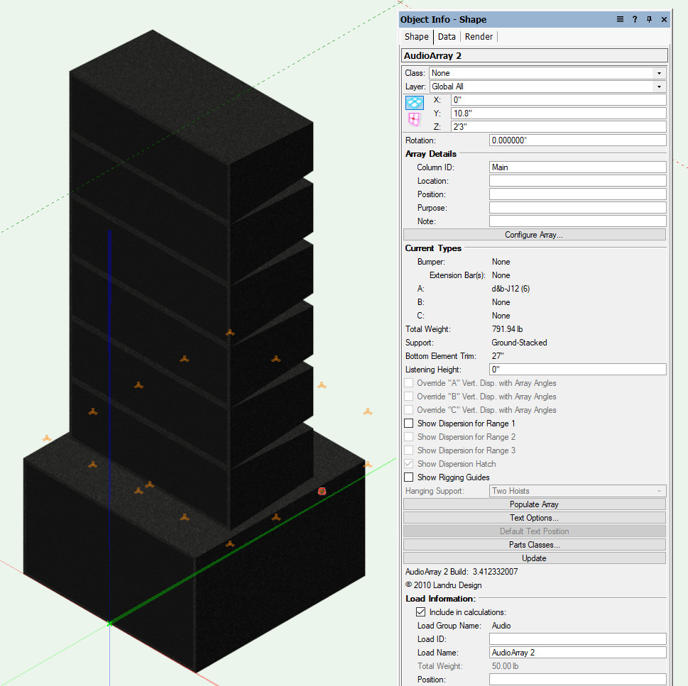
This feature is currently part of the Landru Design version of the tool. Individual module/panel weights can be input, which the tool then uses to calculate, for example, an overall wall weight. As you change panel counts, the weight updates. -
Single, centered image on LED screen, not tiles. How?
C. Andrew Dunning replied to MartinBlomberg's topic in Entertainment
Yes. -
Not just you - though, the default Z value I'm seeing doesn't seem to be linked to any of the model data. And...instances I place have a negative Z value.
-
Single, centered image on LED screen, not tiles. How?
C. Andrew Dunning replied to MartinBlomberg's topic in Entertainment
First: The way that the tool works is that, in the Edit Array Image dialog, 100% scaling means that the image fills the width of the given screen/array. If resulting image is than taller than the screen/array, a portion of the image is then not seen/used. You can use "Vertical Shift" to specify what portion of the image is seen/used. Second: The Spotlight version of the tool only automatically tiles the given image. The Landru Design version of the tool adds a "Tile Image" toggle to the above dialog, allowing you to do things like reduce the scale so that you see the entire "taller" image on a wiser screen, center the image (using Horizontal Shift) and not tile the image, as below: Does that answer your question?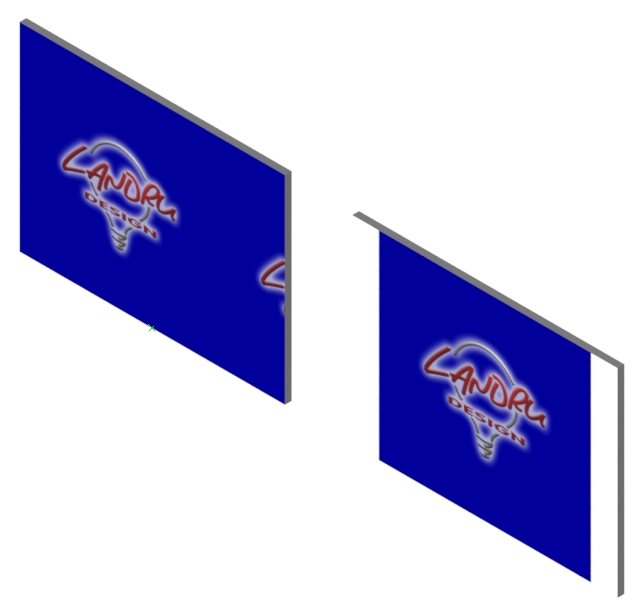
-
Custom Speaker Array Bumpers & Speakers
C. Andrew Dunning replied to Marcel Vellekoop's topic in Entertainment
Pages 23-25 in the manual available here: https://www.landrudesign.com/AudioToolSet.htm might provide the info you need. -
Replace a truss symbol in a configuration
C. Andrew Dunning replied to Mickey's topic in Entertainment
I have. Thus multiple VEs and much ranting and gnashing of teeth... -
Replace a truss symbol in a configuration
C. Andrew Dunning replied to Mickey's topic in Entertainment
Simple...if replacing a longer w. a shorter, a pop-up dialog asks you what you want to do - single or multiple. If multiple, same Resource Selector system asks what the 2nd should be. -
Replace a truss symbol in a configuration
C. Andrew Dunning replied to Mickey's topic in Entertainment
A good question, Sam... My initial thought: Something akin to the way replacing Symbols works - though, more elegant: Select 1 or more Truss objects. Click on a "Replace" button in the OIP. A Resource Selector dialog opens, allowing the user to use that familiar environment to select new truss from a location he/she chooses. The new truss is positioned using its Insertion Point. and that of the piece it is replacing. Sections mated to the non-I.P. end would be "pushed out" or "pulled in" if lengths don't match what is being replaced. If multiple, mated, truss sections are being replaced, replacement sections would automatically mate. If the user is trying to mate differing truss types, he/she would be presented with an alert/error dialog. If the resulting length is different from original, an alert/error dialog to that effect would be displayed. Make sense?