


paulg
-
Posts
70 -
Joined
-
Last visited
Content Type
Profiles
Forums
Events
Articles
Marionette
Store
Everything posted by paulg
-
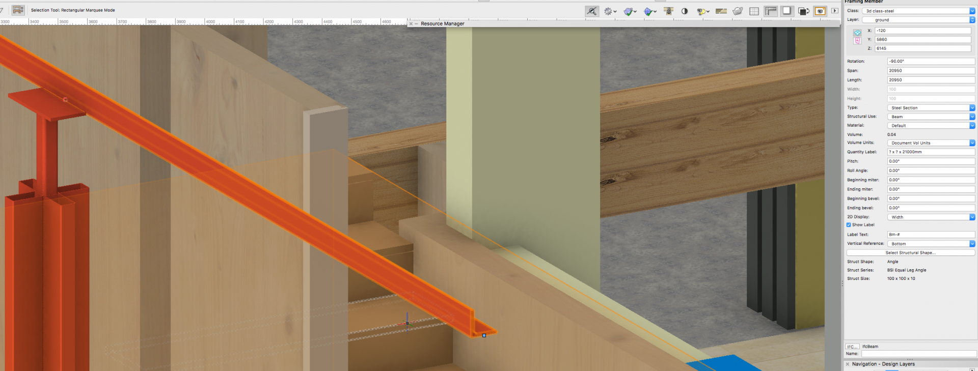
Hi all Problems have arisen with the framing member. I have create an equal angle and placed it in the model. When exported to IFC and opened in Solibri we find that the framing member has revered side! Please see photos. Other than reversing the member in VW and then exporting does anyone one know why this might be happening? Many thanks Paul Using the latest service packs on VW17 and solibri viewer v9.5

-
I think you can set the site modifier pad class to invisible and still have the effect of the site modifier visible. paul
-
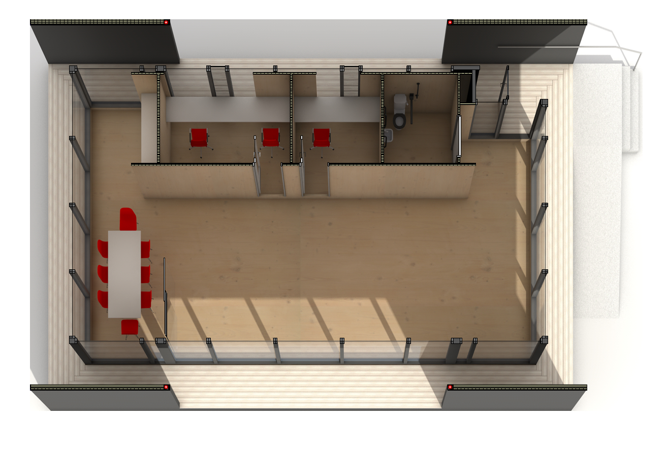
results just in...
-
Amazing... thank you
-
I am trying to create a rendered cut section viewport but in 'plan' orientation. Is this possible? My model is in one layer, its a small pavilion and I want to try placing the section cut at different heights, in order to pick up different features. Any tips would be gratefully received. Paul
-
Hi Flavio I have just started looking into animation myself so found your answer. When you edit the animation a time scale bar is visible. When you drag your views in this a curve sort of connects them. In the top right there is a triangle pointing backwards, double click on this and you can change the movie duration. Best Paul

-
Thanks rDesign. Nice little tip for the 3d loci. Will look into the Cloudcompare software. I couldn't get the previously mentioned Meshlab to open my .pts files. Matt - The point cloud was generated by a survey company so I have no idea about the process. cheers Paul
-
Thanks RussU, that looks pretty cool. I will take a look. If anyone else has some ideas about working with Point cloud in VW that would be useful too. Thanks
-
Hello All Does anyone have any experience with point cloud model? I have a file .pts (actually 3 as they are so big, 3gb each!) which imports great into VW17. I set it to import only 10% of the points, which is fine for me. My issue is that the point cloud model is imported a single entity which I cannot seem to convert into individual points (3d loci). This means I cannot click on one point in the model to gain info on its height. The only way around this is click a new 3d loci on the point i want information from. However this doesn't work as you have to view it in OpenGL so the 3d loci disappears! I have tried ungrouping , converting to 3d polys etc but it just gives me a bitmap and an object with nothing in it. I guess my question is, can you separate the point cloud model into individual points? Also, why do you have to view the model in OpenGL to see it? Many thanks. Paul
-
Hi I think this is unfortunately how it works. Like you I think it would be useful to have it update like symbols. paul
-
Hi I think this is unfortunately how it works. Like you I think it would be useful to have it update like symbols. paul
-
Hi again. I opened a brand new blank file. used a default wall style to draw a wall (clockwise). I then created a window with side opening to make it easier to see what was happening. Grey colour class for exterior, light brown class for interior jamb. Placed in window and look right. grey goes to the exterior face of wall. I then dragged the window out of the wall and the jambs switch sides.... grey is now on the inside of the window. ?????????????
-
Hi The wall is made from components and drawn in a clockwise manor. the windows still flip around when placing in and out of the wall. Tried with a default wall as well! paul
-
If you look closely you can see the exterior jamb is coloured grey and the interior brown. The glass is offset to the exterior jamb. When the window is removed from the wall the glass jumps to the interior face.. Actually looking more closely its the jambs that flip sides. I will look to see if flipping the wall helps. cheers Paul
-
On another note, I can't see why people use class overrides. If you set up your classes exactly how you want them to begin with, there should be no need to override the attributes. Are there other reasons to use them that i'm missing?
-
I can't see us using the Project worksharing feature at the moment. We all work in the same office (not at home or abroad), we have a good folder structure to organise the reference files. I just don't like the idea of having everything in one drawing. We moved away from that by referencing in other files, although some people in the office (no names) still do things in one file and I have to transfer the information in the proper format later. I can see how a project architect might want the final okay before the work undertaken by the 'cad monkeys' is accepted in to live model. I say this and in a years time i'll probably be converted. p
-
https://techboard.vectorworks.net/ubbthreads.php?ubb=download&Number=10770&filename=140402-Work%20Group%20Reference-general.pdf. this pdf helped our office figure out how to use sheets and design files.
-
Also, when using 'exterior wall detail' for windows. I make 1 wall component (external render) return to meet the window frame. Great in plan but this does not work in section or in 3D.al my windows are recessed in the wall i have the insulation showing! I thinking i'm ranting.....
-
Its not ticked. How do I add a photo?
-
Hi all. I have created a window, offset the sash glazing by 50mm to the outside face. Looks just like the IDEALCOMBI FUTURA + window we are using. I pat myself on the back and make a louver version of the same window. I then add it into a wall and the glazing jumps to the inside face of the frame. Same goes for the new louver feature. see attached screenshot for visuals. This is very strange. I dicided to drag a new window into the wall then amend the settings. I dragged the window out of the wall and it does the same thing. anyone else have issues with windows like this?
-
Hi Alan I am using a wall style however the wall height is set to be the 'Layer wall height' rather than a fixed height. I guess a symbol does not have a layer height association as things could go very wrong when moving the symbol to layers with varying wall height settings. The best solution is, as you say, make sure the wall style setting has its height set to 'layer elevation' and then type in the height. attached image of the master plan with the 5 different house types. cheers P
-
How would you go about making a house type that updates in a referenced file? The reason i made the houses into symbols was due to a problem with design layer viewports. I referenced the house types into my terrain model and then created a viewport of the house and duplicated it within the terrain, giving it Z heights as i went (its a sloping site). It worked great but had major issues trying to export the whole model with house in place as IFC and dwg and dxf to consultants. Some parts of the DLV, like walls and slabs are in the correct Z, around 121m high but the windows and doors went back down at 0. I tried many export setting but came to the conclusion that making a symbol for the house was more stable. P
-
Hi All I have made a symbol of a house type which contains walls, slabs, windows doors, etc.. its quite basic as its for a master plan. Whats great is i use scattered over the plan and make changes to the one symbol and its updated. great. The issue is with walls. I needed to add a little wall to the symbol but i can't seem to get it to have a height. The wall style if set by 'layer wall height' the layer is set to 2400mm high. It just stays as a 2d wall. I tried typing the height in the OIP but it won't show any height in the actual wall. I wouldn't have thought drawing a wall in a symbol would be so heard. Does anyone have any ideas. So far i have had convert the symbol, add the walls, make a new symbol and overwrite the old one. Bit of work considering i have 6 house types. p
-
Thanks, that worked a treat. paul
-
good morning I created a viewport of a massing model on a sheet. In the sheet the open GL model is VERY pixelated. I have tried changing every setting i can find to high but still looks and prints badly. The hidden line render to the foreground is fine but the open GL render is super poor. Have we missed something? how on earth do i add a picture to this post? cheers Paul

