taliho
-
Posts
130 -
Joined
-
Last visited
Content Type
Profiles
Forums
Events
Articles
Marionette
Store
Everything posted by taliho
-
@line-weight - yes, for sure.... I did find out that by rasterizing I could drop the whole file down to 18MB (From 129MB!). I think print quality is not impacted. I will keep working on the original file... But - I am most curious why this particular file is behaving this way, while another project that has practically all the same objects, renderings and imports, and is by now 220MB, will export to pdf, with no necessary adjustments , to 16MB. Up til now I though 16MB was acceptable - this thread and all the contributors (thank you all!) are telling me I should be targeting much smaller exports.
-
@Pat Stanford - just saw your comment - so I deleted the site survey layer . -does the 'corruption' stay even when the object is removed? Typically I import any dwg, rvt and skp files into an empty file, clean up/reduce meshes etc as best I can and then copy into my working file. This is a single story single family home. All slabs walls and roofs are on the same design layer I don't have many hatches at all, but I deleted all my 2D details that use hatches and tiles I've changed the rendering style to hidden line with no hatches deleted all symbols: furniture, appliances, plumbing fixtures. (just in case I forgot one that came from skp) deleted entourage deleted wall materials deleted heliodon and lights deleted cameras and purged the file I'm at 100MB pdf. I removed all the design layers except the model layer (no impact) I removed all text blocks (notes, legends etc) from the sheets Dropped to 40MB Back to the original file, removing all the text blocks (without all the other measures I've tried over the last 2 days) - PDF size dropped by 50MB. These are same notes that I have been using in previous project files with no issue. I've been using Tekton fonts for 25 years. The original file is now 72MB with no notes and annotations, if I rasterize when publishing I get 43.7MB Still trying to find "the lion in the desert"...... I may just have to rebuild this file
-

PDFs - Tips for reducing size / scrolling speed?
taliho replied to Selena_VBD's topic in Site Design
HI- I posted a similar issue yesterday. My typical file size for a project is about 220MB - when I publish to pdf I get on average a 16MB file. - then compress further with Adobe. This works for me. But one particular Vectorworks file is 168MB - and publishing to pdf results in 129MB file. All settings are the same as other files. Here is what I tried so far In a test file I systematically and cumulatively - removed all objects outside of the sheet border - removed imported bitmaps, pdfs, sketchup and dwg, - removed all sheets that were not sheets I needed for the project (I sometimes draw a sheet to explore a detail, or a camera view, without including it in the construction set) - deleted the title block (since individual sheet exports to pdf were over 30MB, and the TB was the only common object). The project has 15 sheets so far. - changed the resolution in publish pdf options from No reduction to Low reduction all these steps reduced slightly. The biggest drop was when I changed every viewport to "solid" - the resulting published pdf dropped from 103MB to 20MB. However, back in the original file, when I only changed the viewports to solid, there was no change in the size of the resulting pdf.... I will check on any hatches today. So many non-billable hours...... and no progress towards my deadline..... Thank you everyone for contributing ideas. -
Thanks for the link- I will continue my updates there. In a test file I systematically and cumulatively removed imported bitmaps, also tried deleting the title block,( since individual sheet exports to pdf were over 30MB, and the TB was the only common object). I changed the resolution in publish pdf options. all these steps reduced slightly. The biggest drop was when I changed every viewport to "solid" - the resulting published pdf dropped from 103MB to 20MB. However, back to the original file, when I only changed the viewports to solid, there was no change in the size of the resulting pdf.... So many non-billable hours...... and no progress towards my deadline.....
-
Hi- My typical file size for a project is about 220MB - when I publish to pdf I get on average a 16MB file. This particular Vectorworks file is 168MB - but publishing to pdf results in 129MB file. Any idea what can be causing this? I have deleted imported bitmaps, pdfs, sketchup and dwg and no significant changes in the resulting file size. I quit and restarted - That made the Vectorworks filer larger (?) Thanks Tali
-
Help setting up repetitive residential units
taliho replied to Archistyles's topic in General Discussion
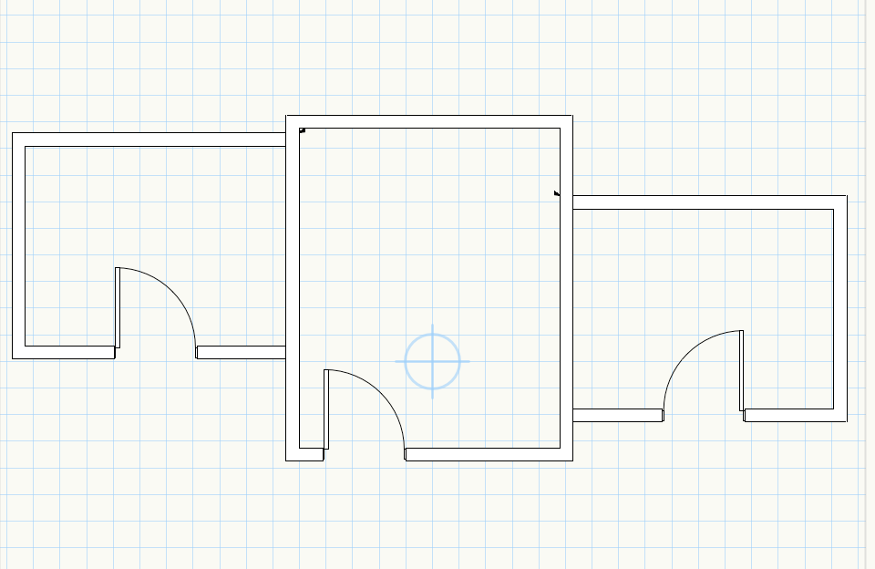
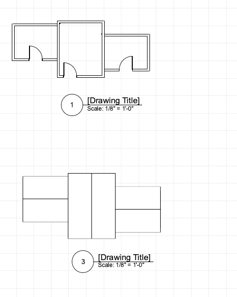
I tried it one file with a very basic plan. The workflow should be similar ? However - I was unable to get elevations and sections, so there may be something flawed after all ... I will be following to see if others chime in. I think DLVS give you better control directly from the OIP, as opposed to editing symbols. Which layers to show, which classes, lighting options etc I drew 2 units. (I tried with the units all on the same layer, for now) floor on one layer, roof on another layer. I cropped each one separately, and placed the viewport on Layer Site On Layer Site I arranged and duplicated, mirrored the viewports, Make a viewport of that to a sheet layer and continue as usual... I think this viewport has to have all layers and classes visible, so that you can control it later on the Sheet Layer Viewports. try DLV.vwx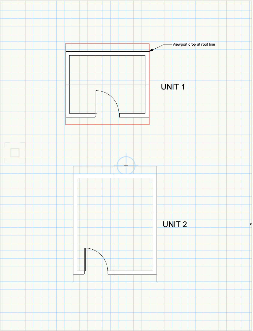
-
Help setting up repetitive residential units
taliho replied to Archistyles's topic in General Discussion
Hi I don't have too much experience with this - but in theory the Design Layer Viewports might work Draw your units, create a separate DLV of each unit type, place it in a new Design Layer eg Floor 1. Duplicate, rotate, the DLVs as needed. You can control layer and class visibility in a DLV, same as on a Sheet layer Viewport From this Floor 1 design layer create your Sheet Layers and continue as usual. If you make a change in the unit design layer - eg plumbing arrangement - it will then show up in all the copies of the DLV. Seems this is what you were hoping to achieve with symbols... Again - there may be someone with better experience here.... Best of luck Tali -
Naming viewports has been very important for me - especially for auto referencing. Vectorworks numbers them by default as you create them, and the order in which they appear on the organization palette makes no memorable sense to me. In order to group them, my system is PLAN-floor PLAN-roof PLAN-reflected etc ELEV-front ELEV-rear etc SECT-A SECT-B etc DET- fdntn DET-roof etc The Sheet numbers are A1, A2... for generating a sheet index. - and again, for autoreferncing details, sections, elevations, etc.... If I forget to name a viewport while creating it, I go back and name it in the OIP Find a system that works for you. Tali
-
Tom- Fantastic!!!!! Thanks. That's exactly what I want. Didn't think of Object Style........... Tali
-
Tom- Here is the file Thanks for taking a look 651555363_WallLegendTrial.vwx
-
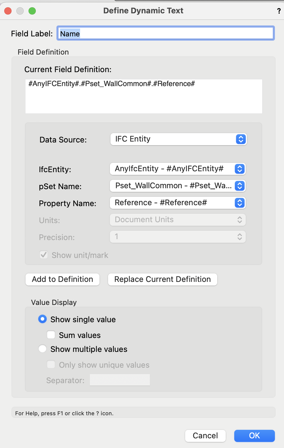
Thanks Tom - That is exactly my problem. It does not display in the way I would like it to - the Name definition displays either the name or the mark, - I am using what Vectorworks set up as a default . #AnyIFCEntity#.#Pset_WallCommon#.#Reference# What do i use to define the Mark? the Mark is reflected in the Wall tag. How do I define it to read the wall-tag?
-
HI I'm struggling with defining the Graphic Legend Field - (no coding knowledge) If Mark is empty on the Wall Style Data Tab, then the Legend reads the 'Name' #AnyIFCEntity#.#Pset_WallCommon#.#Reference# (default from Vectroworks original setup) If there is an entry in Mark, then it reads the Mark . How to define the 'Mark' and the 'Name' from the Wall Style Data tab? Thanks Tali (apologies - I may have posted this on a PM before) Wall Graphic Legend Trial.pdf
-
Similar to @Andy BroomellI have set my printable area as custom size to 12x18, at 50%. I have a 12x18 printer, which is a little easier - but the principal is the same This means I'm laying out sheets exactly as they would look at 24x36, (1 sheet, no breaks) and they print to half/scale on 12x18. You may need a different scale % for 11x17?Page setup.pdf
-
Thanks Pat- I realized I had the advanced properties set to Separate cross section/Use attributes of original class. When set to Merge Cross Sections the Section style class appears Thanks Andy - as you noted - that's what the last file was using.... Tali
-
Hello- I do not automatically get the 'section style' class anymore (I used to in previous versions). Has it been removed in 2022? (did I do that?) I can copy it in in from previous files, but how do I add it back to the Standards? Thanks Tali
-
Lilah- I have seen excel spreadsheets invert text when using an older 32 bit Microsoft Office on the new 64bit Macs, Catalina and newer . The problem may be there, and not in Vectorworks specifically.... Tali
-
Thanks to @Tom W.and @zoomer - My work is mostly small residential projects, many of them slab on grade foundation. Typically I do not need a raft - the concrete is poured into a perimeter trench with rebar. Up til now I was adding the footing/thickened edge as a 2D line on each individual section, (I create a symbol for it) and was hoping that I can model it as part of the building to save time (and work more accurately in clip cube). I have been fortunate to work in mostly flat-land projects, so haven't had to deal with sloped terrain at all, and I was hoping its an easy flow. So I learnt that I can do an EAP addition - I should just do it at one of the later stages of design. That would make my wall sections, using attributes of original objects, look really good right at the first cut. Can the slab perimeter be used as the path? (without drawing a polygon over it). I also tried adding a 15" thick CIP wall below the slab on the same design layer (can't bind it to the slab...) But even if I select both first level framed wall and CIP footing wall and drag to enlarge the room, only one of the walls moves. I don't work in Stories - is that the difference? Thanks again for your time responding to this - on a Saturday.... Tali
-
HI- I'm wondering what workflow will allow me a thickened slab that would be bound to the walls? The hope is that as I develop the design, and move the walls, the slab edge will stretch with them. I drew a a concrete slab on grade w/gravel (from library) and bound it to the walls above. It does what I need, and stretches as the walls move. I tried binding a second perimeter of concrete walls below the slab, but can't bind it to the same slab. I tried adding an EAP to the slab. (thanks @Tom W. didn't know I could do that! learnt something new) This looks great in sections, but does not 'stick' to the slab - when the wall moves, the slab moves with it, but the EAP stays in the original location. Is there a trick I'm not using? Thanks Tali
-
Thanks, I will try this.
-
Hi- Is there a way to publish to pdf without nested bookmarks? My City department does not accept nested bookmarks (huh) Is the workaround to export each page to pdf and then combine them? Thanks Tali
-
Hi- Using hyperlinks for the first time... How can I change the Hyperlink font and style? It does not conform to the class defaults. Is it possible to use the hyperlink inside a callout - or is it a separate object that I need to physically draw an arrow to the object? Thanks Tali
-
Thanks both- I changed to Very High setting which worked great Tali
-
HI- To model a barrel vault, I went to front view, drew an arc, offset and closed open curves extruded. What i got was a segmented barrel vault...... What settings do I need to show it as a smooth arc in section (hidden line) and interior renderings? Thanks
-
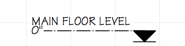
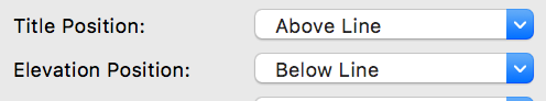
Thanks - Can I move the topic to another forum or do i post a new topic? My settings are with the intent that the title will be above the line and the elevation below the line. It was fine for a while, and now the elevation has creeped up. In the drawing label tool there used to be a place in the OIP to determine the placement of the scale below the line.(no longer there - you need to edit the label for style now) I was wondering if there is a similar way to style the elevation benchmark marker.
-
HI- How can I position the text so the elevation is below the line, not on the line ? Thanks