
jamesmise
-
Posts
179 -
Joined
-
Last visited
Recent Profile Visitors
1,341 profile views


-

One or more operations were aborted due to lack of memory
jamesmise replied to MHBrown's question in Troubleshooting
I just stumbled across this same problem. Most of the time I draw in 1/2" or 1/4" scale. I didn't realize I was in 1:1 scale which seemed to be the problem. I switched to another scale and the error message went away. -
@markdd seems to have found it. I've accidentally done this before myself. I guess every symbol you get from another source like 3d Warehouse, should be opened in a separate file in Vectorworks and thoroughly examined before adding it to a master drawing. Learned my lesson.
-
Can we please have a way to quickly find what objects or textures are increasing our file size? I have to delete objects one by one, then hit refresh, then check the file size to find an object or texture that added 20mb to my file. One time I accidentally used a 10mb image for a texture. When a 50K image would have worked just as well. It took me a while to figure out the problem. Maybe this problem has been addressed and I don't know about. Thanks.
-
I noticed the same thing.
-
Thanks Kevin. I believe the casters were pulled from the Sketchup 3D Warehouse. Maybe that has something to do with it.
-
One other note. I noticed that section viewports are not corrected after the process you described. I'm still working on a way for the section viewport to display correctly.
-
I tried what you said, but at first I did not also convert the sub-objects (the casters). It did not fix the problem. I tried it again and converted it to a group including the sub-objects and the rendering was correct. So it may have something to do with symbols contained within symbols. And as I said, the rendering was incorrect in front and back views only. Side views and isometric views were fine. I will submit it as a bug. Thanks for your help!
-
jamesmise changed their profile photo
-
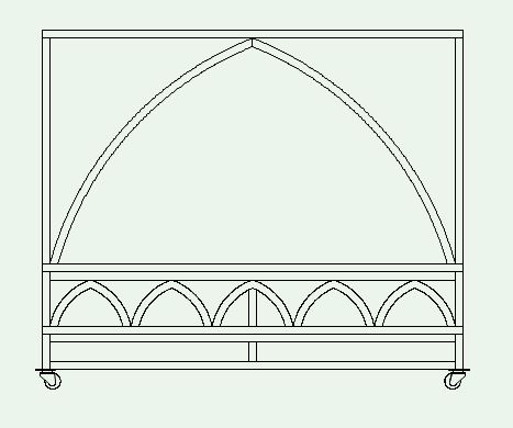
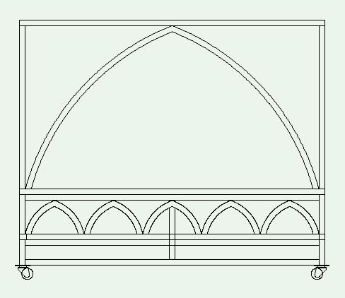
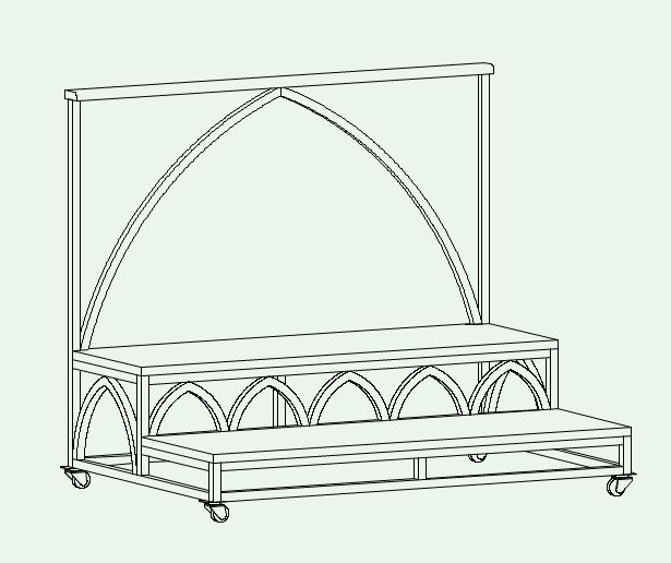
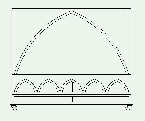
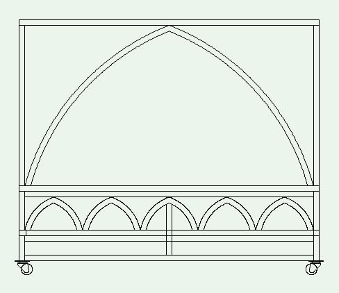
Hidden Line rendering is not displaying correctly in front or back views. Other views are correct. Attached are some samples and a VW file. Sample 1 shows what a front view, hidden line rendering should look like. I had to cant the model a small fraction to get it to render correctly. Sample 2 is a Front view, hidden line rendering and is showing lines that should be hidden, especially in the bottom center of the model. Sample 3 is an isometric view of the model. Any help is appreciated. I can't keep printing my drawings out and whiting out the incorrect lines. Vectorworks 2018 with Renderworks vw problem.vwx

-
Renderworks camera "look to height" changes
jamesmise replied to jamesmise's question in Known Issues
One thing I would emphasize is when viewing a renderworks camera, deactivate the camera before going to walkthrough mode. View changes made while a camera is active seem to change the camera. A little pop-up would be nice asking if you want to change the parameters of the current camera. -
Renderworks camera "look to height" changes
jamesmise replied to jamesmise's question in Known Issues
Just came back to check this thread after having continuing problems with renderworks cameras. Thank you all. I didn't realize i needed to create new renderworks cameras AFTER installing the service packs. Thank you, thank you, thank you. Solved my problems. I've gotten rid of templates created before the updates. -
Create Section Viewports in Custom Views
jamesmise posted a question in Wishlist - Feature and Content Requests
When creating a section of a SLVP, "the viewport you are sectioning must be in one of the following views: top/plan, top, bottom, right, left, front, or back." In the attached Sheet Layer drawing, Flat A is in front view and can be sectioned. But the other two flats are at odd angles in the design layer. The only way I can section these SLVPs is to make them into symbols, put a copy of the symbol on another design layer, rotate the symbol to the x or y plane, and create a SLVP from the rotated symbol. I guess in some occupations, every object lines up neatly on the x or y axis, but I have objects all over the place. So my wish is that I can section a SLVP that is in any view. -
It's nice that when you format text you can see the different fonts, but you have to scroll through the fonts one at a time. It would be nice if the drop down font menu listed the fonts in each one's style. This seems standard in other programs like Microsoft word.
-
I put my symbols in folders in the Resource Browser. I don't see a way to organize Textures.
-
When I edit the polygon in an extrude that has been mirrored, or copied and pasted somewhere else, I cannot see the objects around it anymore. I would like to mirror or move an extrude and have the new location be its new origin when editing so I can see the surrounding objects. When mirroring, maybe one of the options is "reset new object origin". I'm not sure origin is the right word.
-
Editing additions or subtractions
jamesmise replied to jamesmise's question in Wishlist - Feature and Content Requests
Thank you! Why didn't I think of that. Except if you have multiple cutting planes and you only want to delete one.