Asemblance
-
Posts
217 -
Joined
-
Last visited
Content Type
Profiles
Forums
Events
Articles
Marionette
Store
Everything posted by Asemblance
-
Hi All, Is there a definitive list of new tools introduced in Vwx 2019? Specifically tools with 'buttons' which should be in the default workspace? I know there is a checkbox on immigration of workspaces from 2018 to add new tools, but for some reason this doesn't seem to have worked for me. Rather than setting up all my shortcuts and other settings again, I'd rather just manually add the new tools in their appropriate locations.
-
Hi All, Having a problem exporting from a vectorworks 2018 model file sheet layer, where the resulting dwg seems to be scaled to 350% (exactly). I'm hoping this is something obvious we've overlooked our end, any suggestions?? Thanks, A
-

Teaser Tuesday - Class and Layer Filters - Vectorworks 2019
Asemblance replied to PVA - Admin's topic in News You Need
Hallelujah! Looks even better than I was hoping. -
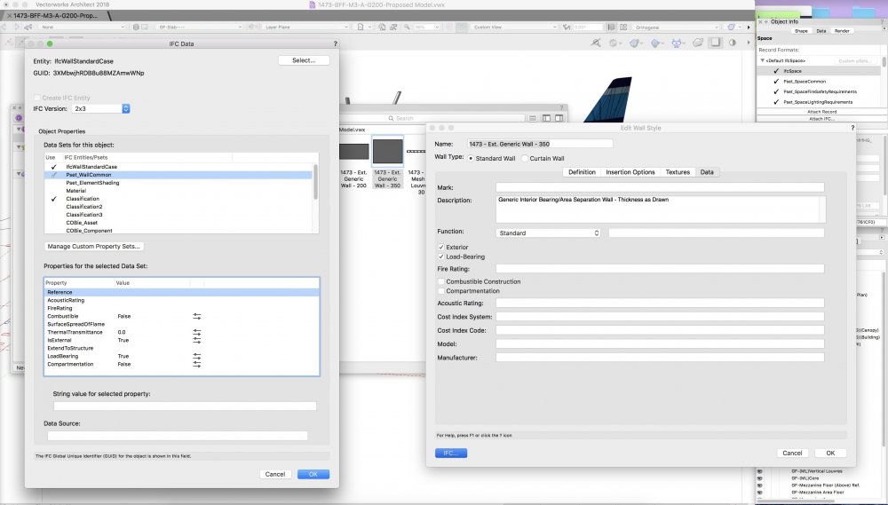
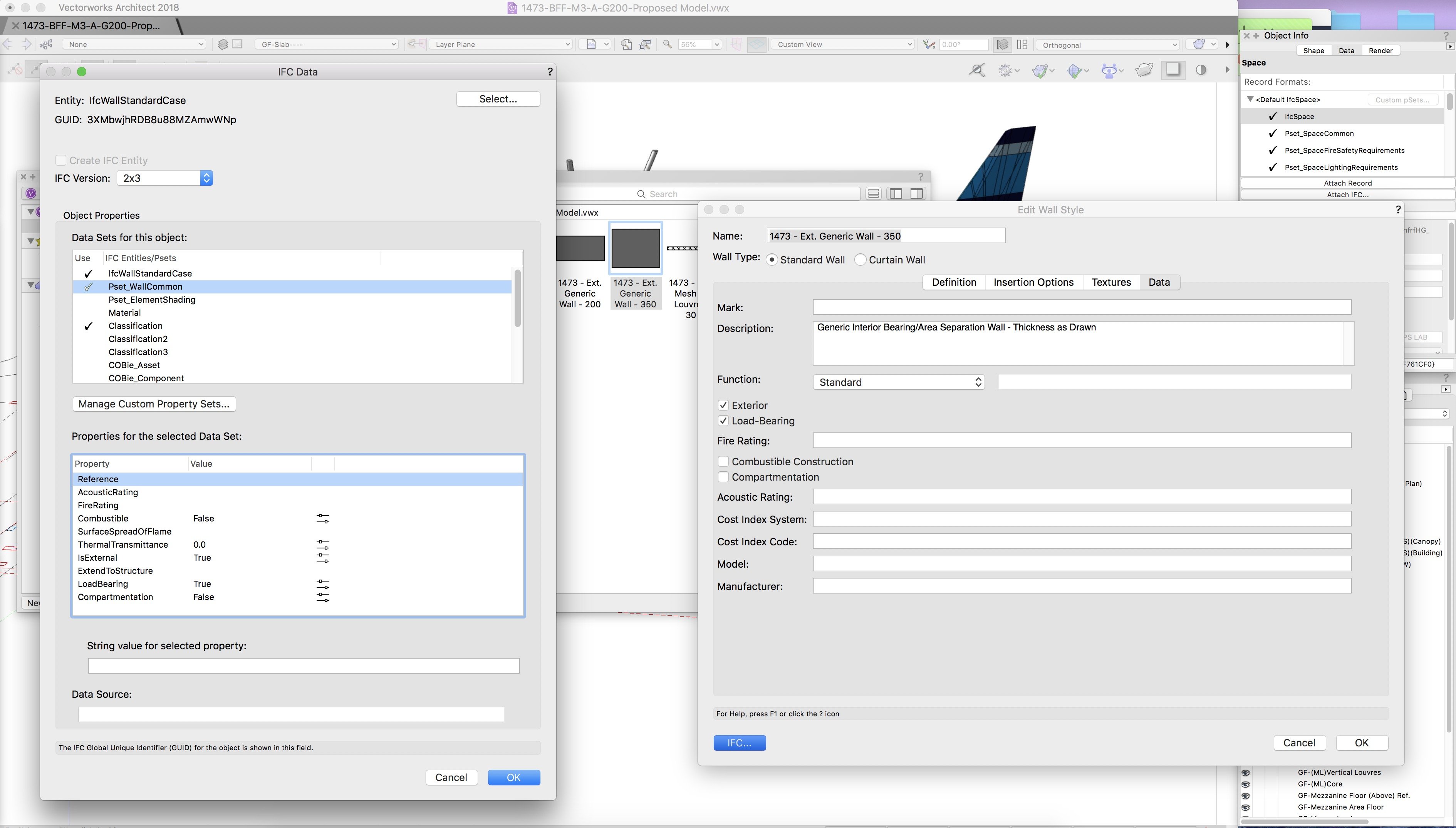
Hi All, Having a bit of a nightmare at the moment exporting an IFC file for our QS on a BIM project from 3D Vectorworks Model. I have been using various wall types, which are largely generic at this stage. Currently 5 core types, 3 of which are generic walls (3 different thicknesses but no buildup shown), 2 of which are curtain walling types. The QS is trying to break down the building into different wall types to put costs against them. They have told us that the IFC Data they would expect to see in the model (which they would use to read these varying wall types) is not appearing when they open our IFC file. Looking at the model in Solbri, I can see that a lot of fields I would expect to be filled in are blank, and the walls are not searchable/sub-dividable by type. Has anyone successfully used wall types in IFC exports? Have I missed a key step where IFC data is added to each wall type? i.e. 'Wall type code', allowing all wall types to be differentiated in the model. Can anyone explain the 'IFC' menu under 'Data' in each wall type? Where on the below screenshot should we be inputting information? The 'global' vs 'single instance' toggle buttons in the IFC data panel don't work how I would expect them to. I would expect this to allow you to set, say, all instances of the wall type in question to have the same 'type' or 'name'. However clicking on the toggle appears to make data disapear, and clear the field. (I can't explain this very well - please try it yourself if you are reading this and hopefully what I'm saying will make sense!) Any advice much appreciated. Thanks, A
-
- 1
-

-
- ifc
- wall types
- (and 2 more)
-
Door Height linked to Story Level
Asemblance posted a question in Wishlist - Feature and Content Requests
The height of a door in a wall is currently pretty dumb. It would be much better if this could be set by story level, i.e. door height = FFL. -
Wall Tool Inside Outside Left Right Marker
Asemblance posted a question in Wishlist - Feature and Content Requests
Hi All, It would be useful if it was much clearer which side of a wall is inside/outside/left/right. Whenever replacing a wall with a new wall style for instance, I've been adopting the trial an error approach. I know the wall when selected shows a tiny arrow on one end, but often this is obscured or out of view. Also (more importantly), this is not displayed if you have more than one piece of wall selected. So the typical workflow of selecting a bunch of walls to update/replace, guess a side to align, get it wrong, undo, redo, select opposite side align. Whilst I'm on it, a marker showing 'inside' and 'outside' of window objects when selected would also be handy. -
Thanks all. @zoomer, I ended up doing option 2 as your recommendation above which produced a nice 'clean' result. I need to familiarise myself more with this style of modelling.. @Kevin McAllister & @markdd - I then tried to get the lofting approach to work, and was exactly as you suspected! Required reversing direction on one of the NURBS curves. I'm glad you also mentioned the manual method, as that feels like its going to come in useful down the line if struggling with some complex geometry or imports..
-
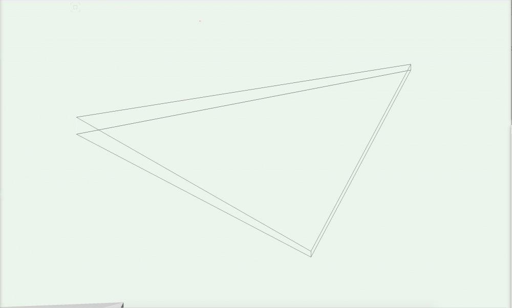
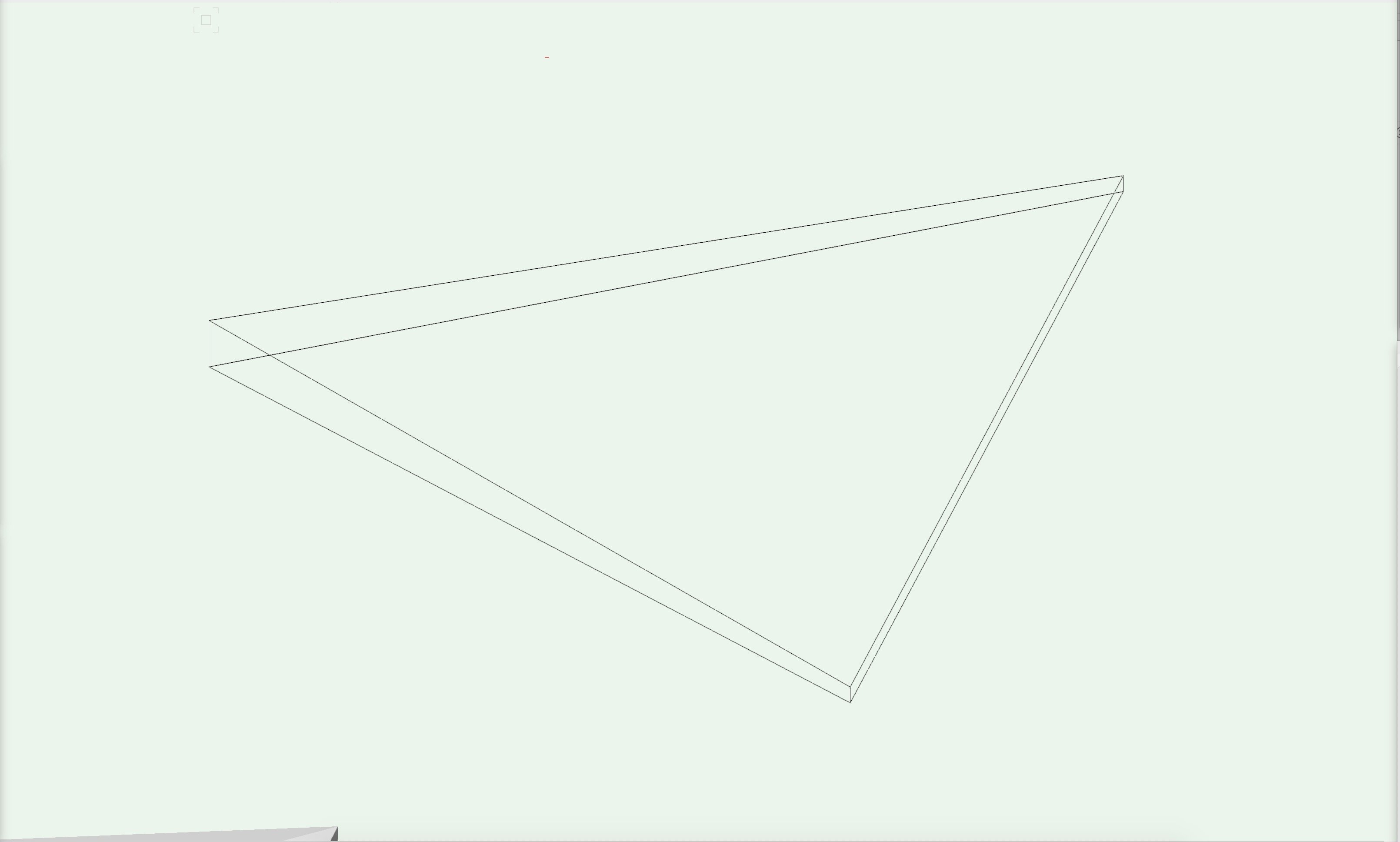
Hi All, I'm trying to create a solid from two triangles on skewed planes (screenshot below). I'm relatively new to the freeform modelling side of vwx so I'm hoping theres something obvious I'm missing. Could anybody please advise how to approach this? As a secondary question, I tried converting both to NURBS curves and lofting but this fails. Can somebody explain to me what the limitations are on lofting that are stopping me from doing this? Is it due to the skewed planes? Thanks in Advance, A
-
Update - The only way I can get this to work properly in IFC export (on attempt 11), is to use 'unstyled' curtain walling. Which is impractical for the project I am currently working on.
-
Window textures and geometry in IFC export
Asemblance replied to taavilooke's question in Troubleshooting
Also having this problem -
Having a problem with Curtain Wall objects exporting to IFC currently. Problem arose after exporting a curtain wall to IFC, then opening to view in Solibri. The glazed panels did not display with a transparency. After a maddening process of trial and error, I still can't seem to resolve this. It seems that no matter what curtain wall style options or class settings are used, either the glazed portions of curtain walling are not exported, or are exported with a solid fill. Somebody please tell me I'm missing something obvious! On another note, the curtain walling tool could really do with an overhaul. This should be a simple process.
-
IFC tagging: control of appearance (e.g. transparency)
Asemblance replied to Christiaan's topic in Architecture
Also struggling a bit with transparencies in IFC export. Did you get to the bottom of this @Christiaan? -
Hi All, I am having some trouble with a section viewport created from a clip cube. I want to alter the location/size of the clip forming one of my section viewports. I can go into the viewport, see the clip cube and move it. However when I exit the modelspace back to the viewport, the section cut is not updated to match the updated clip cube. Is this working as expected? Do I have to delete this viewport and form a new one if I want to edit the position or size of the clip cube? Thanks, A
-
Structural Member Tool... Missing profiles
Asemblance replied to RussU's question in Troubleshooting
This lack of UC's in the structural member tool is biting me yet again, so back for my bi-yearly complaint.. Please tell me this will be resolved in 2019! -
Thanks for your thoughts @RickR, I've also had problems with origins moving etc. However in this case the roof appears on the correct place in the model once referenced in. It just somehow moves in the export to IFC process!
-
Hi All, Does anybody know how to place disclaimer/copyright text inside an IFC model for exchange? I can't find any advice about this anywhere so far.. Apologies for the raft of questions I'm currently barraging the forums with. I'm actually surprised by how few threads there are regarding IFC - perhaps not many BIM users yet? Thanks, A
-
Hi @RickR - Yes that was also my thought. As you can see from the screenshot above (where the roof was IFC tagged in the referenced file), this geometry does show up. But for some reason it is displaced. I can only assume this is something going on behind the scenes, mostly likely to do with layer levels or origins or some such?? It feels like it should work but I'm missing something.
-
Hi @Jeffrey W Ouellette - We have a model containing the building, and a seperate model file containing a complex roof arrangement which is being referenced into the main building file. This is how we would prefer to structure the file for various reasons. Is it not possible to attach IFC data to referenced models then? P.S. - Screenshot below, the referenced roof does appear (outline block for the time being). But it floats approximately 14m above where it should be.
-
Hi All, Great thread, thanks @taavilooke. Has anybody had any experience of adding IFC data to Referenced objects? i.e. Viewports in the model? Struggling to get this working at the moment, the referenced info in the viewport shows up but is displaced.
-
Service Pack 4 for Vectorworks 2018 Released
Asemblance replied to PVA - Admin's topic in News You Need
Has anybody had any problems getting this update to install on Windows 10 systems? For some reason 2018 SP2 installed on my windows machine fine, but SP3 and SP4 wont install. Running setup the installer extracts to 99/100%, and then disappears and nothing happens.. Edit: Installing in safe mode worked second time around, resolved. -
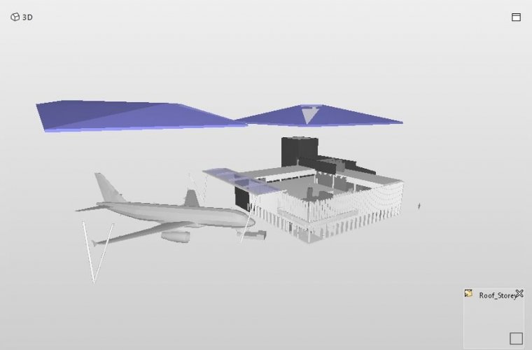
Hi All, I'm trying to export an IFC model for a BIM project, and have run into some problems with grouped objects. Hopefully something I'm just not understanding properly.. When I view IFC data I've exported, any objects contained in a group seem to shift from their correct positions. Screenshots attached, of the same objects not grouped, then grouped (you can see how the row of 4 blue panels shift out of position). Have I missed something? Any tips?? Thanks, A
.thumb.jpg.099f3ecd9cbdfff2f60f2a1001945e89.jpg)
notgrouped.thumb.jpg.4392401fe65cddfdec86de397786fa35.jpg)
grouped.thumb.jpg.648633302ac4956bb57c741334e58688.jpg)
-
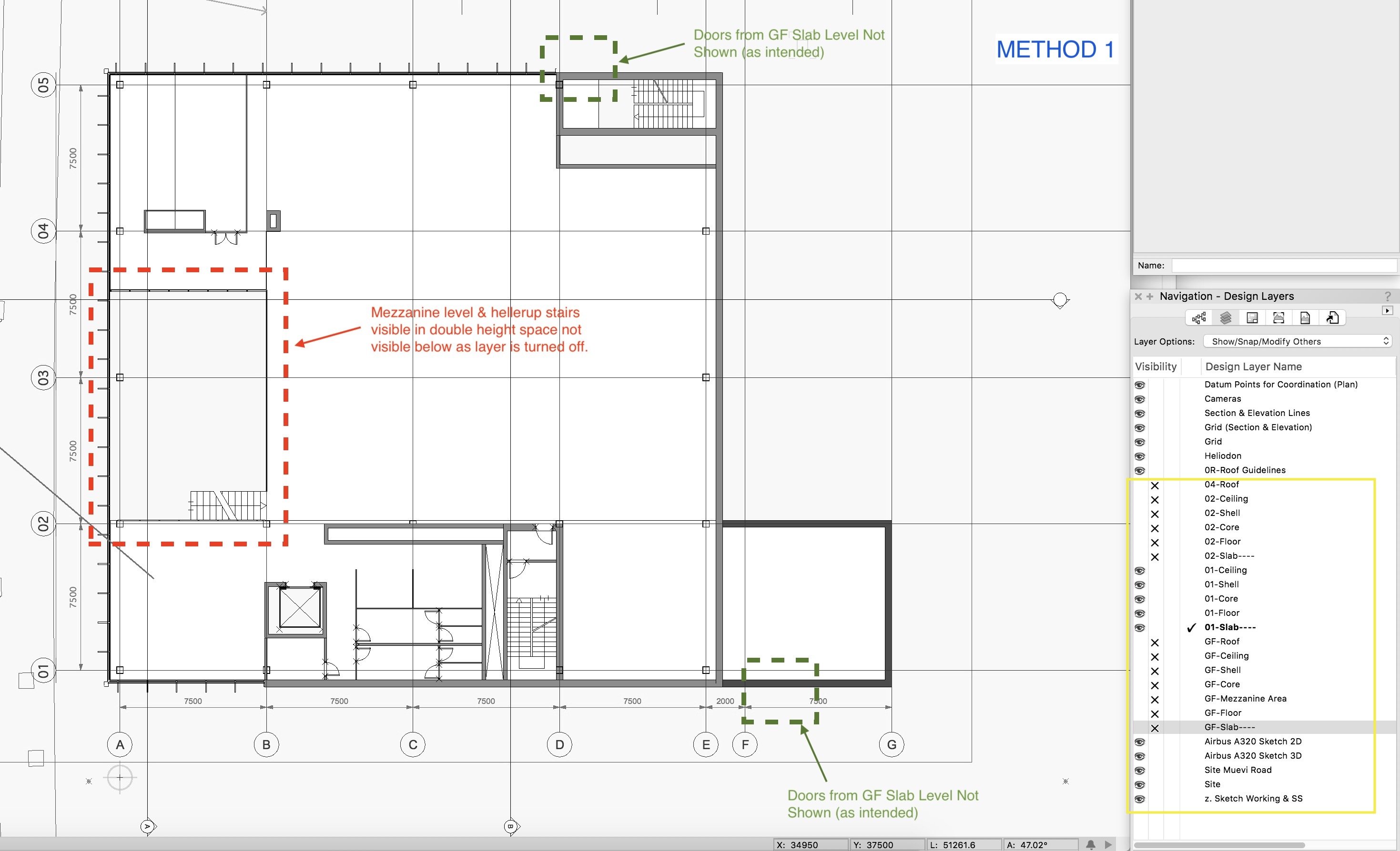
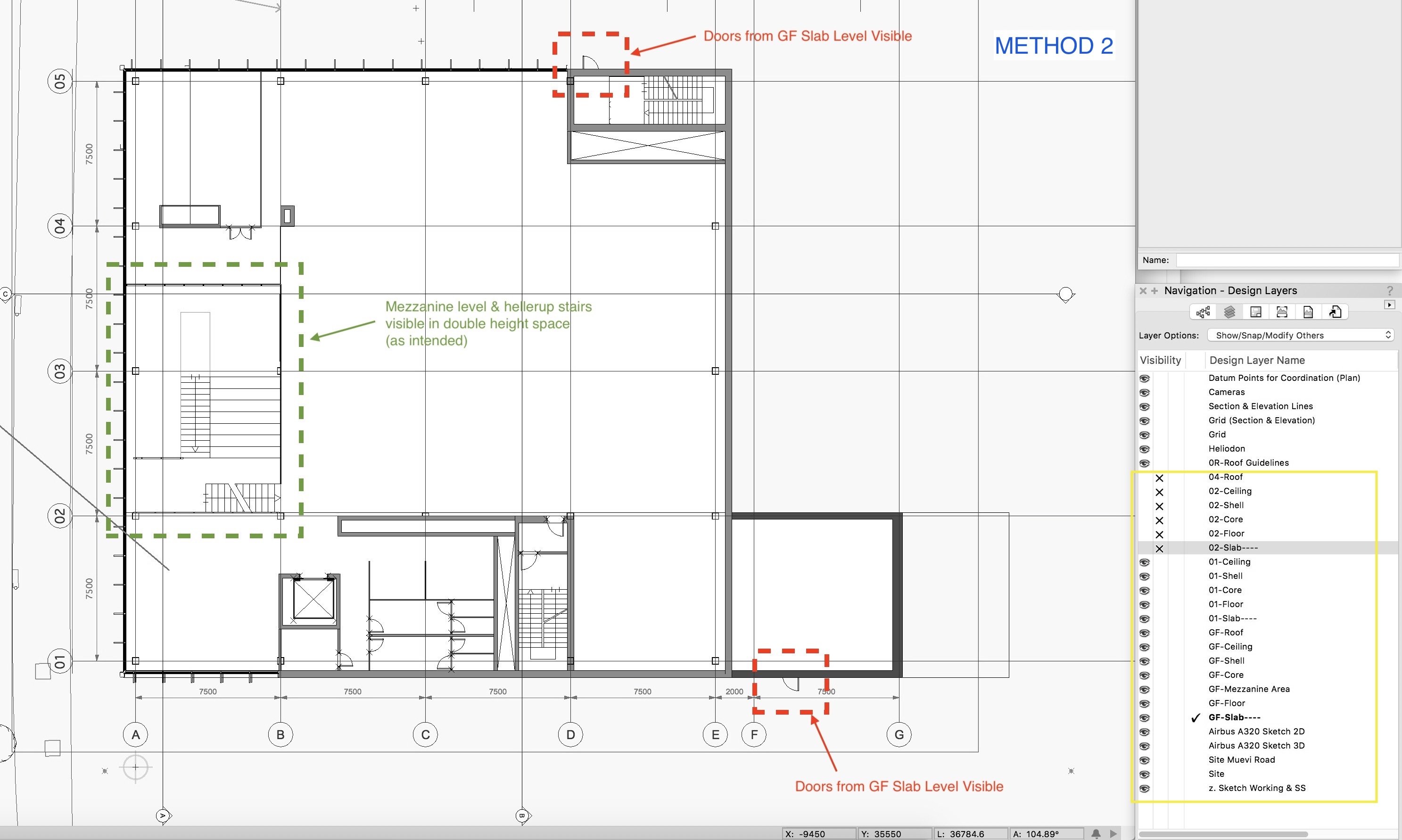
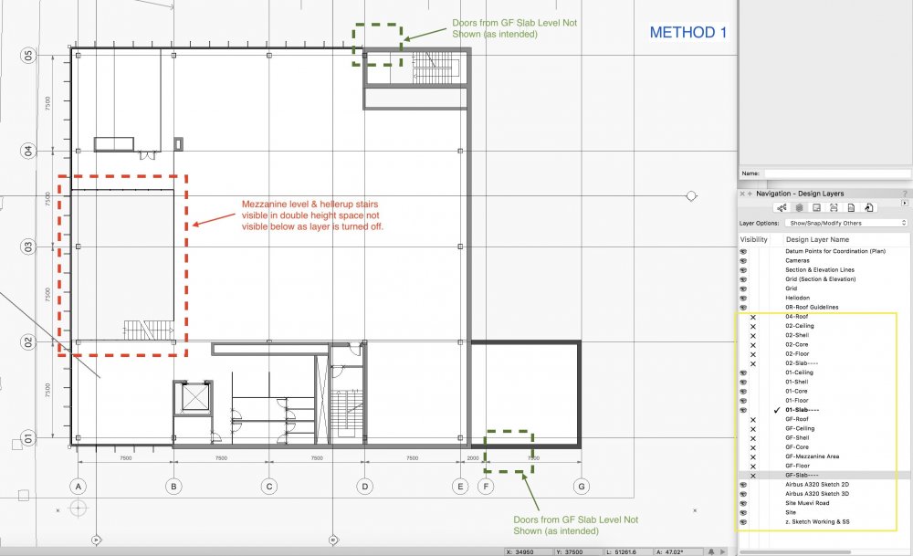
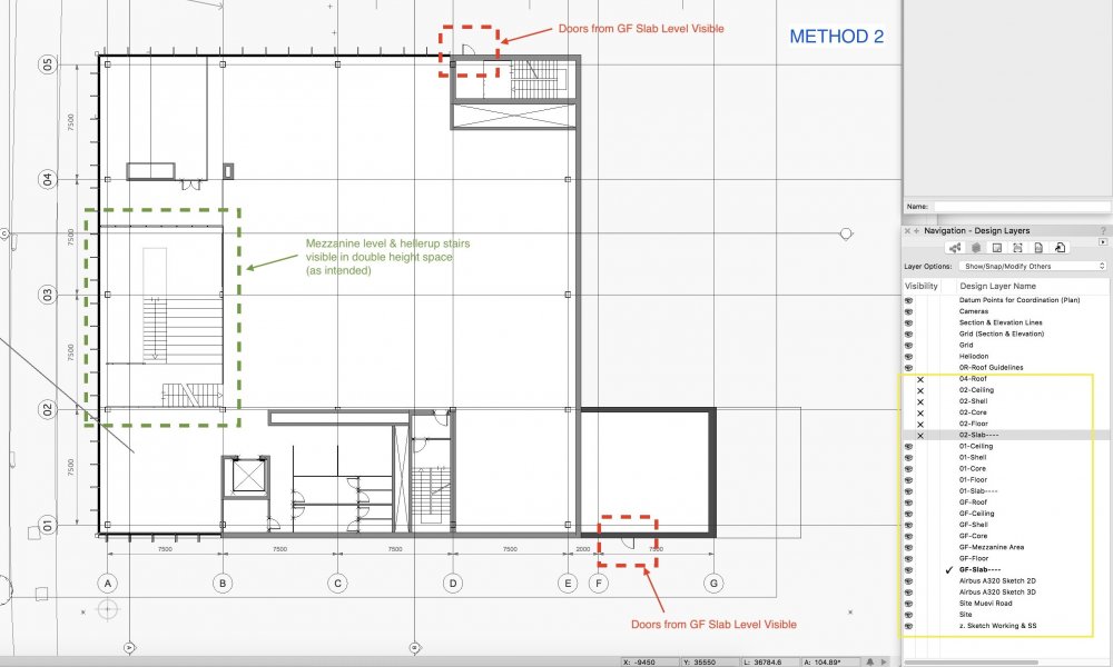
Thanks for everyones responses so far. I've created a couple of screenshots to illustrate the type of issue I'm running into with each of the 2 methods I outlined.. As you can see, in this particular instance the conflict is between door swings from the level below which I don't want to see, and a mezzanine below in a double height space/void, which I do want to see.
-
Hi @CipesDesign, Thanks for getting back. The main thing I'm trying to determine, is which of the 2 options I outlined above is best for creating 2D plans. What you have described would work for option 2 - for instance cutting a hole in the slab to show stairs below. I guess I'll need to take a couple of screenshots to illustrate what I'm asking..
-
Hi All - quick bump here I'm still unsure how to move forwards with setting up our 2D plans! Thanks, A
-
Modelling in 3D - Move object to specific global 'Z' value (i.e. 0)?
Asemblance replied to Asemblance's topic in Architecture
Thanks All, useful stuff! As you touched on @bcd, I also need to get used to checking which plane I'm drawing on, as have been caught out a few times now (aligning geometry in the 'z' axis using a side view, then finding out its jumped a mile into the distance on the 'x' or 'y' axis. I can see this is going to become a common frustration..).

.jpg.de7ae304ca0bb9955018bec3be7dd490.jpg)
notgrouped.jpg.08c8ca28b5a5c13d41a7d68ab5b20bf8.jpg)
grouped.jpg.7d50a4d7ef4b06c832079590e7ed2dfe.jpg)