


mike-h
-
Posts
130 -
Joined
-
Last visited
Content Type
Profiles
Forums
Events
Articles
Marionette
Store
Posts posted by mike-h
-
-
Thanks for those thoughts. As we are paid up VSS subscribers I gave them a ring, they are aware of it as a shortcoming (surely we just want an option to cap wall at openings, preferably with some control - brick/ masonry return, timber lining etc., to outside and inside - maybe related to the splayed openings tool?). Meantime suggestions were just workarounds. What I have done is align working plane to the wall, draw a rectangle the size of the opening, offset and extrude it to make a window lining which is what we would like to do as we move to working drawings, but its a bit labour intensive for where we are at the moment (Pre-Application enquiry)!
Mike
-
 1
1
-
-
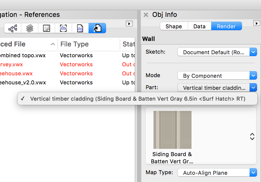
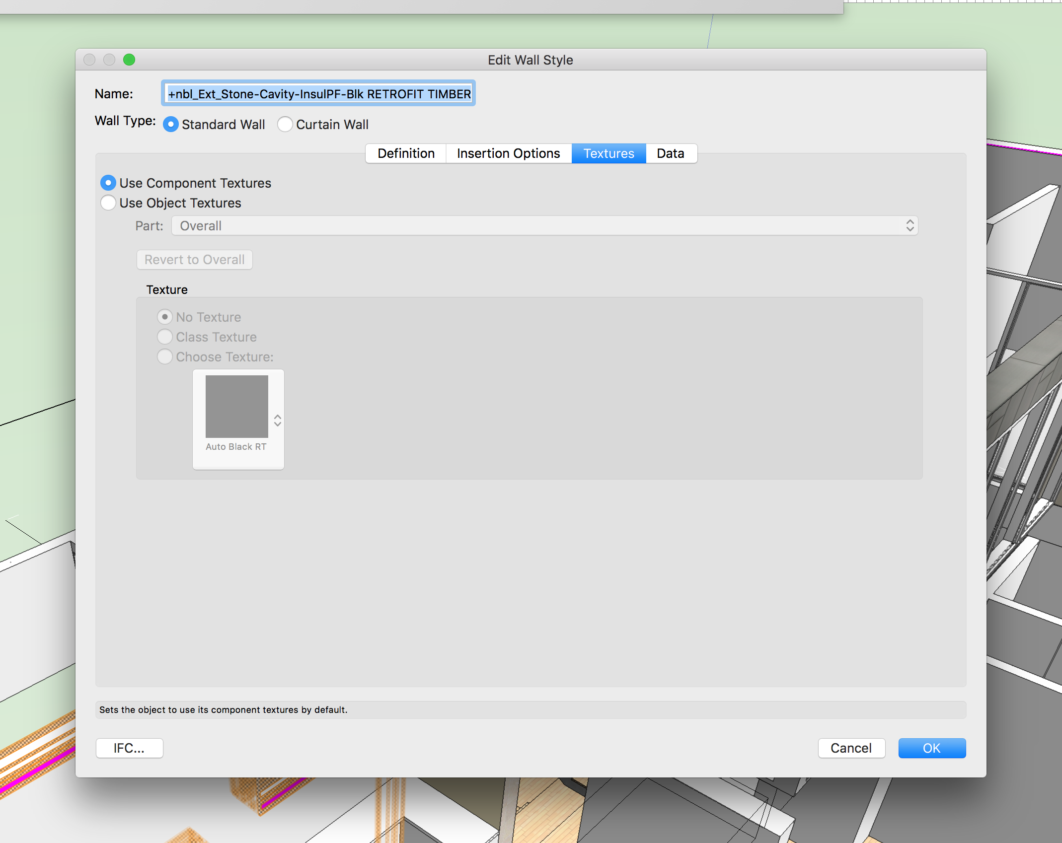
Thanks Jim, I am working with styled walls and am keen to continue doing so. If I go to Edit Wall Style then the option to texture the holes only appears if I abandon the component textures, which loses all the detail of my wall build up. If I just look in the object info palette then I am rendering 'by component', but that is a wall style and doesn't give me the holes option - it seems to treat the wall as a single component if I understand correctly. If I change it to 'by object', then as with the Edit Wall Style route, I lose all the detail and textures from the wall. This must be a common issue surely?! Particularly as the pink insulation layer is the VW default within an (adapted) VW wall style?
-
1
-
-
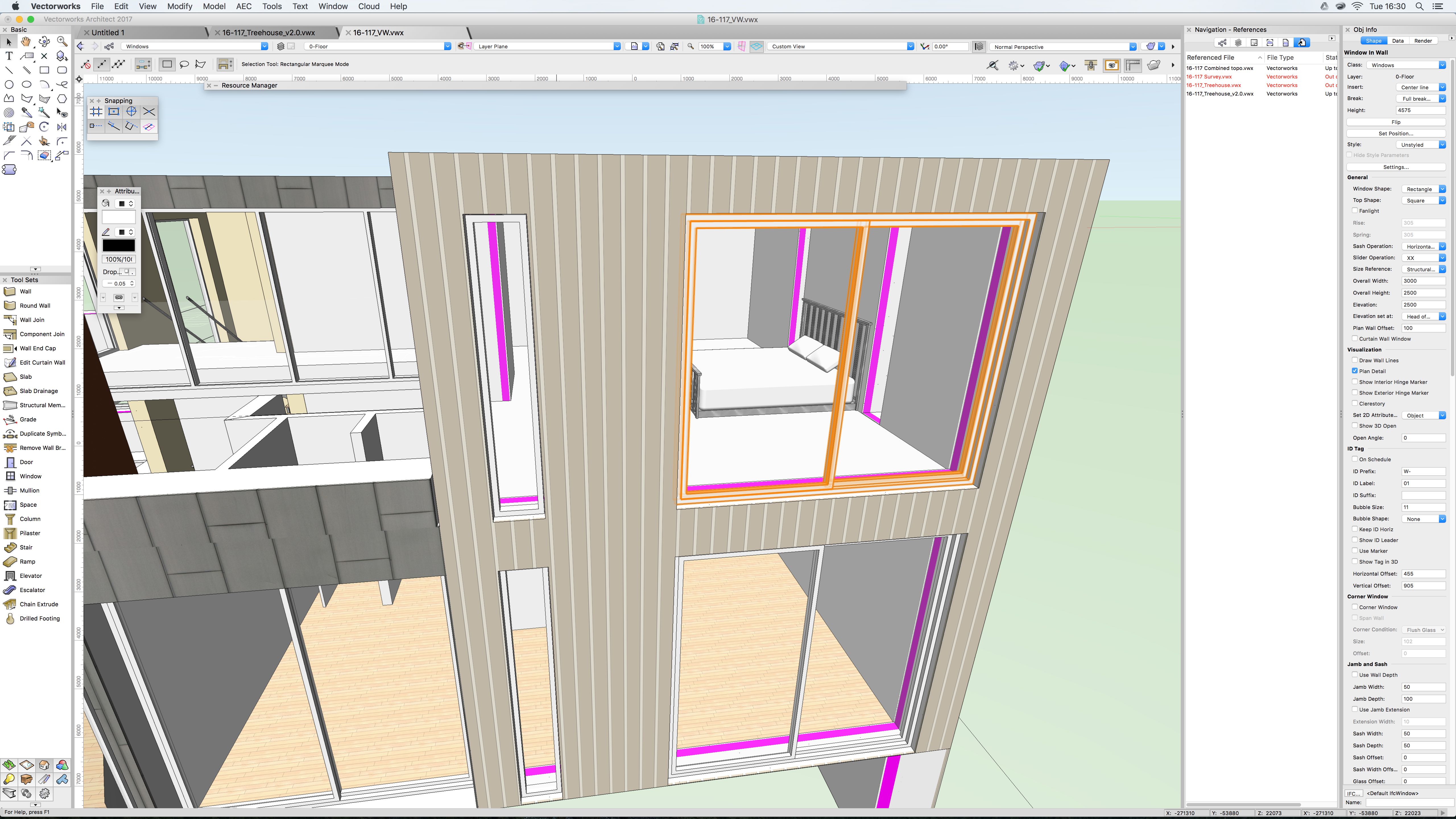
Thanks for the reply, Screen grab attached inc obj info palette.
-
Hi all
This thread comes close to a query that I can't seem to resolve despite some searching. My door and window openings show the full wall buildup, it makes sense to me to cap the walls at the openings, preferably with the external/ internal finishes running up to the windows (set back 100mm from outside and similar from inside. Zoomed says "For openings in Walls created by doors and windows, you will set these Cap settings in doors or windows settings.", but try as I might I can't see a reference to capping within the Window settings, or the object info palette for the windows. Can anyone give me a pointer? Apologies if I have a blind spot on this one.
Thanks in advance!
(VW2017 imaci7)
-
Thanks Peter, as you say, not very intuitive compared to what we're used to. But installed now and having a play around, I've been looking for such a tool for a long time!
Cheers!
Mike
-
Thanks Peter, it looks just the job but I can't see how to install it!
Under Workspace Editor I go "Edit the Current Workspace", find the 2 leader lines under Tools, then once highlighted the only options seem to be "OK" or Export Workspace to Text File. If I click on OK i get the window shown as attached. Clicking OK doesn't seem to add Leader Lines to my tool palette - how do I access the 'modified workspace'? (and I thought the point was to modify the current workspace, not create a new one)?!
Thanks again,
Mike
-
wahey, Eureka! Now why didn't I see that?!
Thanks a lot, thats a great help
Mike
-
Simple drawing of a line 3mm in length, that as far as I can see, should have a marker at each end?
thanks
Mike
-
Thanks Jim, I don't think its the scale - if I draw a line at 1:1 on the sheet layer there is still nothing visible. The marker is default settings of 3.17x3.17mm (circle actually, rather than an arrow) and I have my units in mm so a line of 3mm should have a circle of similar proportions attached, I guess?
I've also tried drawing a line of 3mm on a design layer & still no marker visible!
Mike
-
I'm doing some basic annotation on sheet layers of a 2D drawing.
I would like to put an arrowhead type object on the end of lines.
I have a class called 'notes - sheet", which is showing 'markers' as arrows, but I can't see where there is an option to use or not use these markers.
In the attributes pallette I have Line Endpoint Style set to Class Style but no arrows appear when drawing a line.
If I manually change Line Endpoint Style to a particular arrowhead it still doesn't appear when drawing a line.
Its a simple 2D drawing, but I'm precious about graphics so don't really want to use an annotation tool, I want to create a number of notes within a single text block then arrow the relevant bits of drawing.
Got a feeling I'm missing something simple, but... any help appreciated.
Mike
-
Hello, I'm looking at 3D modelling in VW after a break of a few uears using mainly Sketchup. I have inserted a number of trees from the VW Plant objects library and altered the spread/ height via the plant settings button on the Object info pallette. This gives me the (my custom size) plan dimensions I want in 2D, but when I switch to 3D & render they're all the same size (unrendered, the rectangle increases). Have I missed something or has anyone else found this a problem?
Thanks
Mike
-
Thanks Mitch thats a great help. I've been working with the copy/ paste for a while, but generally been irritated by scaling/ relative location issues (partic with drawings like surveys created by others).
I think 2nd and third options will give me some new ways of working to experiment with & I can see a few useful possibilities. eg. If you only want a limited number of lines/ objects they can temporarily be put on a new layer/ class in the referenced file, the viewport updated with other layers off, then break the reference to import. Thats the sort of thing I'm after, though it still seems a bit of a complex way round compared to selecting lines/ objects within the viewport and copy/ pasting.
Though as there seems to be little interest in this as a topic, maybe its just me!
Thanks again,
-
One thing that has troubled me for a while... I use Microstation at the day job and VW for my projects, which I prefer.
However, using Mstation, if I have a 2D reference I can simply copy& paste any lines or the whole drawing into the new file and start work again. I haven't found any such facility with VW - is it possible? I seem to end up with layers of references that I would rather were just lines in the master file, but don't want to trace them all out! (and snapping to references within references sometimes seems problematic too).
Any words from the wise appreciated!
Thanks,
Mike
-
Thanks folks, I'm not sure quite what worked but re-importing the dwg metres - mm seems to have cracked it. I can't see how the rest of the drawing scaled correctly before with the exception of 2d symbols? Must behave differently somehow.
Thanks again
Mike
-
Can anyone help? I'm just moving into 2009 and have a file setup to reference a survey drawing (Autocad imported to vw2009 then saved as a .vwx). All seems well, except that all the 2d symbols within the survey drawing are 1/1000th of the size they should be in the new drawing file.
I have set all layers in both files to be 1/20. If I set all layers in the survey file to 1/1000 the problem is still there.
Any ideas? I seem to be stuck on this one..
thanks
Mike
-
Aha!
So simple and yet that has managed to escape me for a long time. Well worth the ask! Many thanks for the help on that one Ray,
all the best,
-
Hi does anyone know if its possible to set a preference for the default font when using the text tool? The way I work every bit of text I use I manually alter from the Geneva to the particular font I want to use, which is pretty labour intensive.
Any help gratefully received
Mike
-
I have a VW12.5 mcd file I haven't worked on for a month or so, but had no problems with before. I now have VW2008 and converted it to a .vwx and resaved. Now I find that trying to print from sheetlayers crashes the programme. I reopened the last .mcd file in 12.5.3 and found I have the same problem there - anyone experienced similar, or any ideas? Files created since, in 2008 are printing fine...
cheers
mike
-
Doh!
just found the layer I sent my northlight off to whilst making a stage-by-stage construction sequence. Funnily enough once switched to visible...elevational problem resolved, operator incompetence to blame...
thanks
mike
-
Mike,
Submit a bug for the "fake wall" in the Window PIO Settings Dialog. This should not be happening.
File another regarding the way extra lines are showing between closely spaced windows.
Jeffrey - what do you mean by 'fake wall' - is that the extra lines side and top of the window in the screenshot posted? If so I am sure that is also the cause of the extra lines between closely spaced windows. Are you saying you haven't seen these occur before?
I've not submitted a bug before, but will try and do so...
mike
-
hi brudgers,
the northlights aren't 'in' anything (as in not like a window-in-wall), I built up the frame (effectively a big open web, or vierendeel girder) from extrudes and just positioned the windows. I kind of understood that windows don't need to be 'locked in' to show up - see Damondesigns suggestion for rooflights
http://techboard.vectorworks.net/ubbthreads/ubbthreads.php?ubb=showflat&Number=110266#Post110266
they show up allright on the hidden line so I know they're in the right place.. do I need to do further monkeying to get them to render? Would it be better to use a 'wall' for the beam? It seems odd that they're there but not showing, the girder that contains them also seems to still be letting light through...
cheers
I've just tried it with a wall instead - results attached. Looks fine in 3D (at least you can see the frame) but in elevation you'd struggle to guess whats there).
-
just to follow that, attached is the latest render. Windows have improved, but you can see the problems caused by the extra framing (partic by french doors top left, between windows lower left). But I just don't know what is happening with the northlights, clearly visible in the hidden line version. The framework (in red) is built up of extrudes, to represent an assembly of glulam elements, these are all textured as 'paint glossy attr color', the windows are positioned in the frame and settings adjusted for clear glazing, jambs etc as 'style-1' as above - but what's going on in the render??? any ideas welcomed!
thanks
mike
-
one thing that seems to be helping is tidying my windows into single units with multiple elements, but a recurring problem I have is unwanted framing around the outside (see picture). How do I get rid of this? If I deselect the sill option it goes, but so does my sill. I thought I was stuck with it but I have managed to produce a window without, but can't work out where the settings differ...
thanks again
mike
-
SORRY! time to update my profile - I just went over to 2008 a couple of weeks ago. I hope you've not dug too far Jeffrey, apologies...
Thanks for the help... if I've got it right I've gone to each window individually (selecting a whole bunch then adjusting the settings doesnt seem to work as it would for, say, selecting multiple viewports then adjusting class visibilities), gone to 'view' then set all the 'jamb & sash', 'sill' etc to 'style-1' and 'glazing' to clear. Then in the class organisation palette I've set 'style-1' to plain white fill and 0.05 black pen.
This seems to have made things more consistent, but some frames still don't seem to show up, would it be better to apply a texture to style-1 (I just want plain white-ish frames really, and don't want to increase render time with unnecessary textures if I can help it). I'm not sure if I grasp the basic concept of how un-textured objects render and how opaque they are - they seem to come up in photographic grey - what is the best plain white texture to use as 'default' if things are generally better textured than not. (other items seem to work fine in default rendered grey). Am trying now with style-1 as 'paint glossy attr. colour'. (and where does the eyedropper come in?).
thanks for your help - sorry if I'm rambling or have missed the obvious but I'm new to the rendering game, having satisfied myself with hidden line in the past...
also...I notice that for doors, sidelight glazing options does not include 'clear', and does the glazing in the actual door count as 'int/ ext panel'? as there is no door glazing option...
Intersecting pitched roofs
in Architecture
Posted
I know this has been raised before, in different variations, but I haven't found the answer to my specific issues. We have a project with several intersecting pitched roofs, that also meet/ overlap the walls. I am struggling to get the geometry to meet satisfactorily and would really like to be able to manipulate the roof faces with 3D handles. It seems that if i join roof faces, the cut line continues down at the angle of the intersection, rather than finding the wall that I also want it to meet. If I edit the roof face, this happens as if the roof face was a flat polygon, and when I exit the editor then issues with the junction between the roof faces arise. In these sort of scenarios am I better to abandon the create roof/ roof face tool and model as 3D solids of some sort (and not have the BIM roof build up available) or are there options that I haven't explored. As I understand it within Archicad roof vertices are editable in the same way as a 2D polygon, which would be very helpful here. In all the instances attached the projecting gable roof wants to come back to meet the wall of the main building below the gutter line of the main roof, whilst forming a neat valley at the junction of the roofs.
Thanks in advance for any assist.
Mike