

Peter Neufeld
-
Posts
722 -
Joined
Content Type
Profiles
Forums
Events
Articles
Marionette
Store
Posts posted by Peter Neufeld
-
-
Hello mjm,
I agree with your observations and likely request that in the Lighting Device Edit dialogue>Light Information pane it would be good to have the following:
Light 'on'
Light 'off'
Light intensity slider and field.
Then with multiple instruments selected the user could make their choice and click the 'Apply to All" button at the bottom of the dialogue. Much nicer than the somewhat fiddly Visualisation Palette plus it allows users to make the selection separately.
Scott - out of interest do you have many viewports showing lighting devices? This could be one reason for slowness as the instruments get redrawn in the viewports I think.
-
 1
1
-
-
Hello,
Make sure you have 'Display Planar Objects' checked in the OIP. Also bitmaps won't show in hidden line - you'll have to use OpenGL or some such.
Cheers,
Peter
-
1
-
-
On 01/09/2017 at 0:14 AM, gdraper said:
So im looking to improve my workflow for creating Truck Packs for Touring Shows. Where i need to lay out all the cases and gear before hand.
Have you checked out Dom C's RectPack node in Marionette?
There are 2 layers in the file. On the 'part input' layer you draw the size and quantities of the boxes that need packing.
On the 'Plug in" layer in the OIP set the size of the space and then the type of sorting etc you want to use. It's partially in German but mostly understandable. It looks like you can create and name your own layers and have the Marionette object work to specific layers in the pull down in the OIP. However it is 2D only....
Dom C is a Marionette genius!
Cheers,
Peter
PS it doesn't work on symbols only primitives it seems.
-
1
-
-
9 hours ago, line-weight said:
As an aside, relating to multiple view panes. When I first tried them, I watched the relevant getting started guide, which told me that I should enable them from the "view" menu. However, for me, the command exists in a menu called "New", which I worked out after a bit of confusion.
Hello,
This means that you have used the default option when upgrading to 2017 and the Migration Manager has, by default, migrated your old workspace from 2016 (presumably) to 2017.
IMO this migration of workspaces should be off by default and users who radically customise their workspaces would be aware of this and turn it on if need be. However for most users who might only change one or two things, if any, this is a real trap.
It means any new commands are 'orphaned' and end up in a waste ground area - the 'New' sub menu. I have no idea where the new tools end up probably, no where. It is always best to try and rebuild a workspace if you have to, so that you can start afresh and use the new version's workspace it was designed for.
You'll need to go to your Vectorworks user account>Workspaces and move out (or rename) the old carried over workspace. Upon relaunch you should see the current one from the application folder alongside yours if you renamed it or not if removed obviously but the 'correct/current' be will be loaded from the application folder.
Cheers,
Peter
-
Hello,
Actually this is a very interesting point. Saved Stipples in a drawing can only be applied to certain objects e.g. hardscapes.
They can not be applied as a fill choice to other primitive planar objects as one might expect although the hint is that they are unavailable from the Attributes Palette so this makes sense. You can use the 'Create Objects from Shapes' command to apply a Stipple to one of those types of objects. However, it only works with the first stipple in the drawing. If you have multiple stipples in a file and make one the 'active' one and run the command then it won't be applied, rather the first one in the file. Or so it seems. I might report this.
Stipples otherwise have to be drawn and if you double click a saved stipple you'll get taken to the quaintly (or possibly incorrectly) named 'Internal Tool Tool' to draw the shape. Stipples are great but can be very processor heavy.
Cheers,
Peter

-
Hello lgoodkind (sorry I don't know your name),
No problem ranting - software 'first' releases can do that to anyone. I'm certainly no computer technician but I agree, on paper, that Vectorworks 2018 in principal should be working well on that machine but then again the technology that was expensively and spankingly fast 8 years ago might not be relevant to how the program works most efficiently now. Is this issue related to the one file or all DTM's? (forgetting roof styles etc). As Kevin notes, report it as a bug and get it to Vectorworks, Inc. Also it's not a question of 'not supporting' processors either. Vectorworks can run on a lot of machines depending on a) the operating system and b) the chips, but that does then equal the performance enjoyed.
You are right though that (in my opinion) I am saying that users should update their hardware frequently. Every 3-5 years is about right. If you spend more upfront on the hardware then it might last 4-5 years. Otherwise change every 3 is my advice to most people. As we all push and expect more from our software and hardware, it's easy to forget to keep both up to date. Yes it costs money. BTW Vectorworks Service Select is undoubtedly the most cost effective way to maintain the program, plus all the other benefits.
The other thing I have to ask is do you update the Apple operating System with the very first release or do you wait until the first .1 or .2 update? As you attest the same might be true for new Vectorworks releases too, but it's never a simple answer.
Cheers,
Peter
-
Dear Michael,
Yes you are absolutely right. Spotlight doesn't use IES data but Josh's premise is a good one though.
From the Help re Custom Renderworks Lights: "The brightness value is obtained using the integral of the raw emission data provided with the file. The file must be a text file with industry standard intensity distribution data in .ies format."
So, if Renderworks already renders a custom light accurately from the .ies load distribution file, surely we can also get a practical photometric grid readout as well?! Of course, it is always easier said than done, and I have no idea how, but it's as if we're half way there already.
Cheers,
Peter
-
15 hours ago, lgoodkind said:
I can elaborate and I will do so as I find problems however - again this is taking up a lot of time already.
First Our hardware
iMac retina 5K 27inch late 2014
3.5GHz Intel Core i5 (4 cores)
16GB 1600 MHz DDR3
AMD Radeon R9 M295X 4096MB
1TB FUSION DRIVE
Mac Pro (early 2009)
2 x 3.33 Ghz 6-core Intel Xeon
64 GB 1333 Mhz DDR3 ECC
NVIDIA GeForce GTX Titan 12288 MB
255 GB SSD, 2TB SATA
Mac Pro, (Early 2008)
Serial, G88431HZXYL
2.8 GHz Quad-Core Intel Xeon
32 GB 800 MHz DDR2 FB-DIMM
Graphics: ATI radeon HD 5770 1024MB
120GB Solid State SATA Drive
Macbook Pro
15.4” 2880 x 1800
2.6 Ghz Intel Core i7
8GB 1600 Mhz DDR3
500GB SSD
NVIDIA GeForce GT 650M 1024 MB
Hello lgoodkind (sorry I don't know your name),
I might well be wrong and please forgive me if I am, but it appears your youngest machine is 3 years old and your oldest is almost 9 years old.
The iMac retina 5K 27inch late 2014 is a good one and you shouldn't be having too many issues with that. I'd be interested if you can replicate all the problems you are observing on that particular machine.
All the other machines are well below par for running Vectorworks 2018.
Go to this page: http://www.vectorworks.net/sysreq to see the system requirements for 2018. Note that there are several 'levels' from minimum to recommended to best in terms of multi views and so on. Anything below 2GB of VRAM isn't going to be able to handle DTM's etc very well. Ok for straight drafting and so on but not for higher level work. I'd say that's almost certainly the crux of the matter.
Cheers,
Peter
-
Dear Josh,
I agree it would be great to 'enhance the workflow' and have the options to plug in architectural lighting load distribution files for level comparison. The programs I have seen doing this type of thing seem fairly rudimentary and seeing that Spotlight has the ability for theatrical fittings it would be great consideration for Architect. Mind you where does it stop - sports fields, roads, airports etc etc. Maybe a third party can do it?
I'm not an architect but I believe there is also more and more call for daylight simulations and analyses. Not just shadow studies but using 'standard' defined skies for a lumen count in interiors. So it all seems a good fit.
BTW, since version 2016 users are able to tilt the Spotlight photometric grid to any angle, including vertical. Check the options in the OIP.
Cheers,
Peter
-
Hello,
You can't just say this without elaborating. Are you on Windows or Mac? What version of the operating system are you running? How much VRAM do you have on your GPU's? Do you have the latest drivers installed, etc etc...
Cheers,
Peter
-
I realise that is the crux of the matter but he did not elaborate other than saying it took a few hours. I do not know his process I'm afraid.
Cheers,
Peter
-
On 12/09/2017 at 5:32 AM, J. Wallace said:
Hello
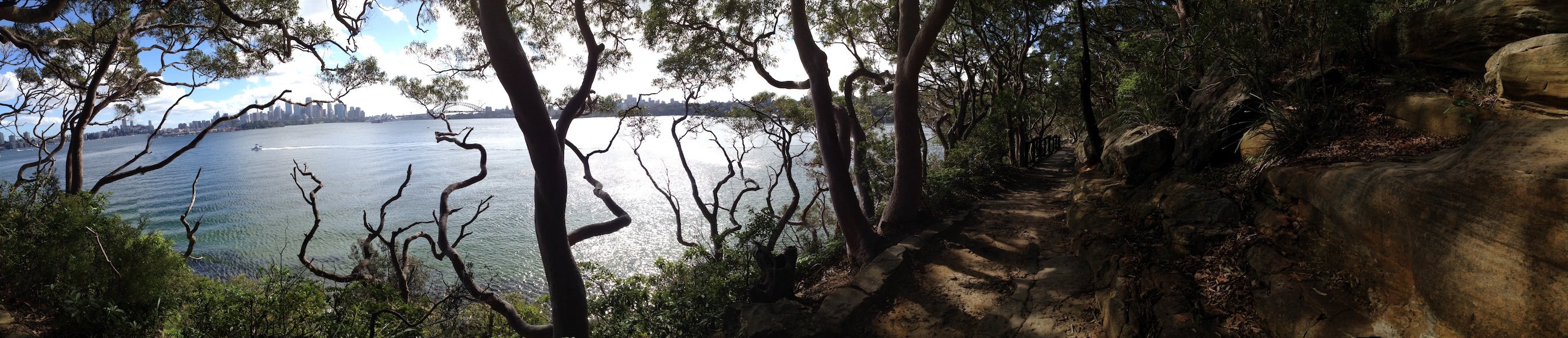
Just wondering if anyone has any experience working with Lidar maps or .las files. I imported a .las file via import>Import point cloud and it worked flaslessly. Now I have over 11 million points...yikes.
Not sure how to move forward with this as I'm hoping to get some contour information out of the file but I'm thinking VW alone might not be able to do this. Any comments are much appreciated. Thanks
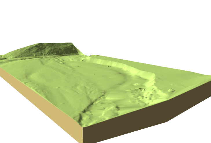
Yes I have experimented with getting the LIDAR data into a Vectorworks Site Model. See enclosed snapshot which is of a large area made up of 160,000 + points. I had to get the data converted to a cvs file by the surveyor to use as the source data for the Site Model in Vectorworks. So it is not a point could, rather a Vectorworks Site Model.
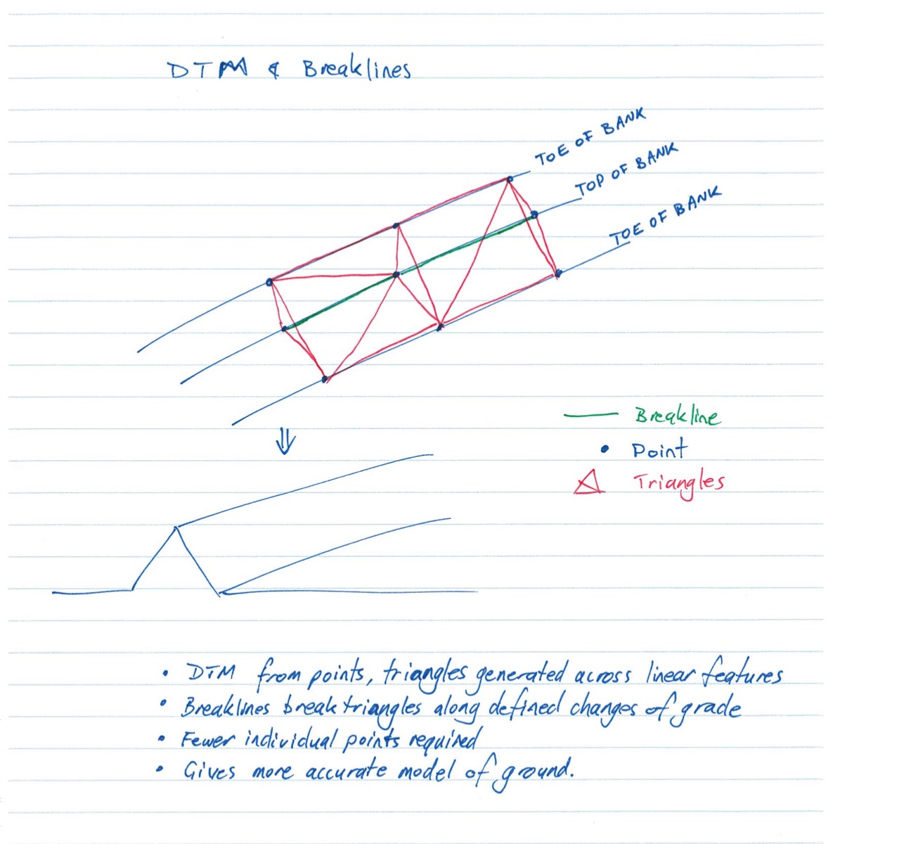
This did get into some semantics regarding accuracy of using points versus the original breaklines that composed the LIDAR terrain in the first place. From the surveyor:
"Even a high density of points is no substitute for breaklines in modelling terrain. We regularly use LiDAR data with an extremely high point density, and find the model not sufficient for detailed design, because the format does not allow for the detection of discrete breaklines. As a matter of course, when generating a DTM, I look over the triangles that a generated and usually have to reverse as many as several hundred on a single model, just to make sure the model matches the ground. There is more to generating a good DTM than making triangles from individual points!"
I was surprised at this level of accuracy as the resolution from LIDAR is obviously very high but then again I'm not a surveyor and was only facilitating and experimenting a method of getting the LIDAR data as source data for a Vectorworks Site Model.
In my ignorance he sketched the differences between the breakline and the triangulated DTM which I include. This is probably obvious to you but I needed to be educated about this myself. Note the bit about 'triangles generated across linear features". Anyway I include this FYI.
Cheers,
Peter
-
3
-
-
Dear James,
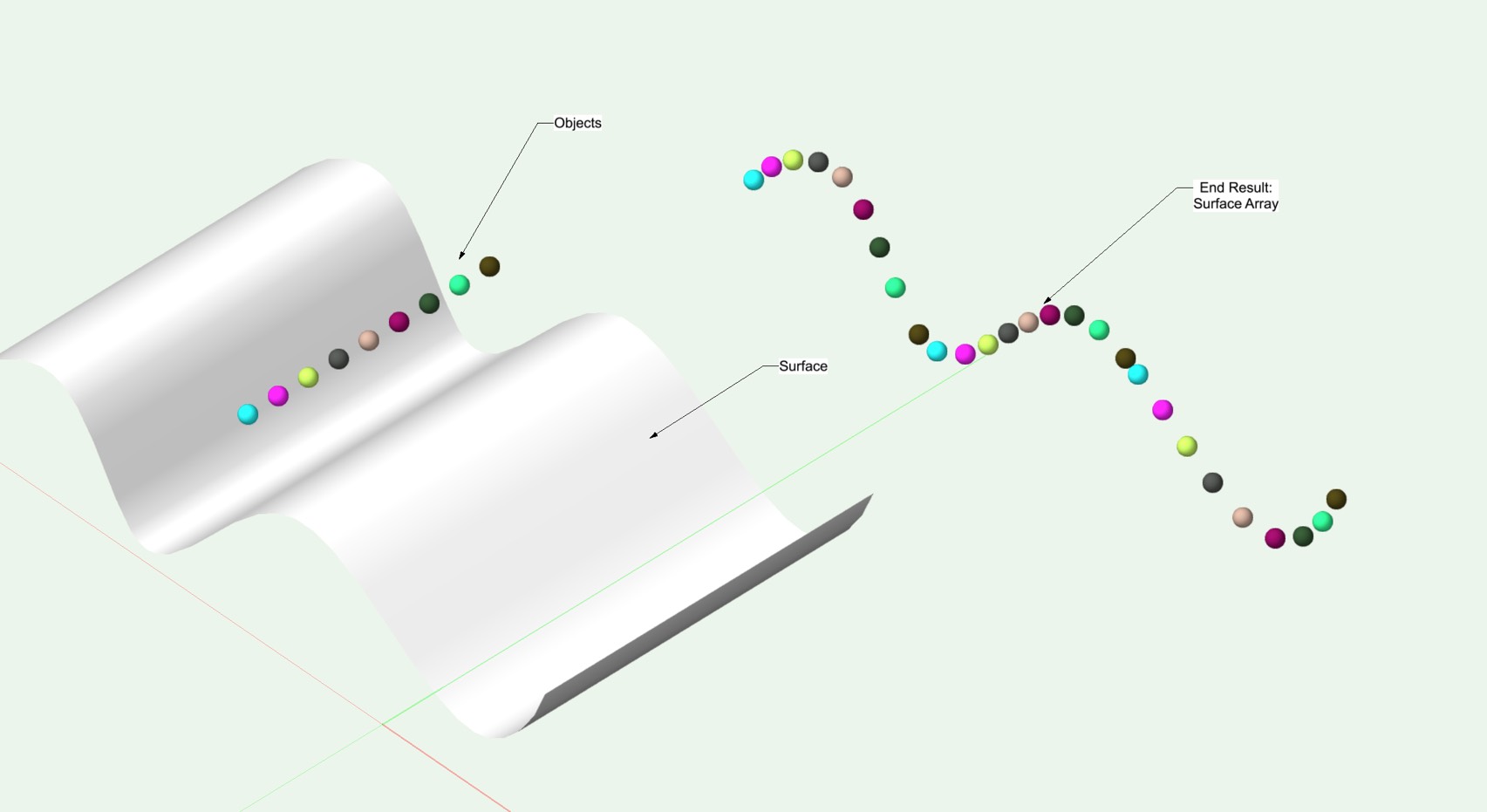
There's no tool that can do that in Vectorworks but there is a workaround.
If you know how far apart each object should be, then place them that distance part. They can be grouped if need be.
Then draw the NURBS surface and run the Surface Array command.
Cheers,
Peter
-
2
-
-
Thanks Scott! A bit of tomfoolery especially the Image Mag on the screen.
Cheers,
Peter
-
Here you go for a bit of fun:
Cheers,
Peter
-
1
-
-
Agree this is very interesting!
Cheers,
Peter

-
2
-
-
Very useful thanks.
Peter
-
-
Not using the transparency shader as there are no real world dimensions. However don't forget the LED tool!
Cheers,
Peter
-
On 13/10/2016 at 4:51 AM, djobbins said:
Hey guys! Does anyone have a sample file of this I could look at?
Dan
Hello,
I noticed the file didn't make it across the forum revamp recently so I'm posting it again as a version 2016 file.
Cheers,
Peter
-
1
-
-
Andrew,
I can only get back as far as version 12 (not 2012 - version 12 released 2005!).
They are available in that version and if I recall even earlier versions.
Cheers,
Peter
-
1
-
-
- Popular Post
- Popular Post
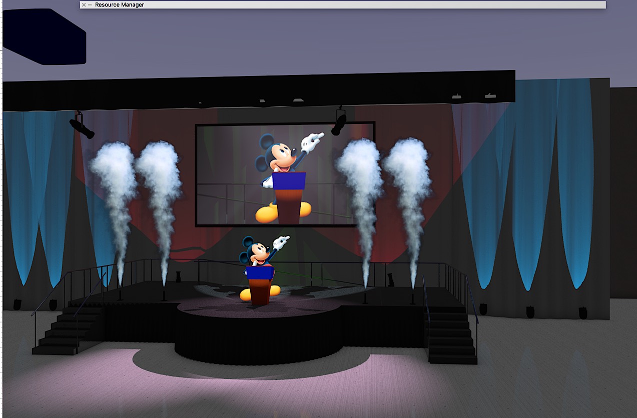
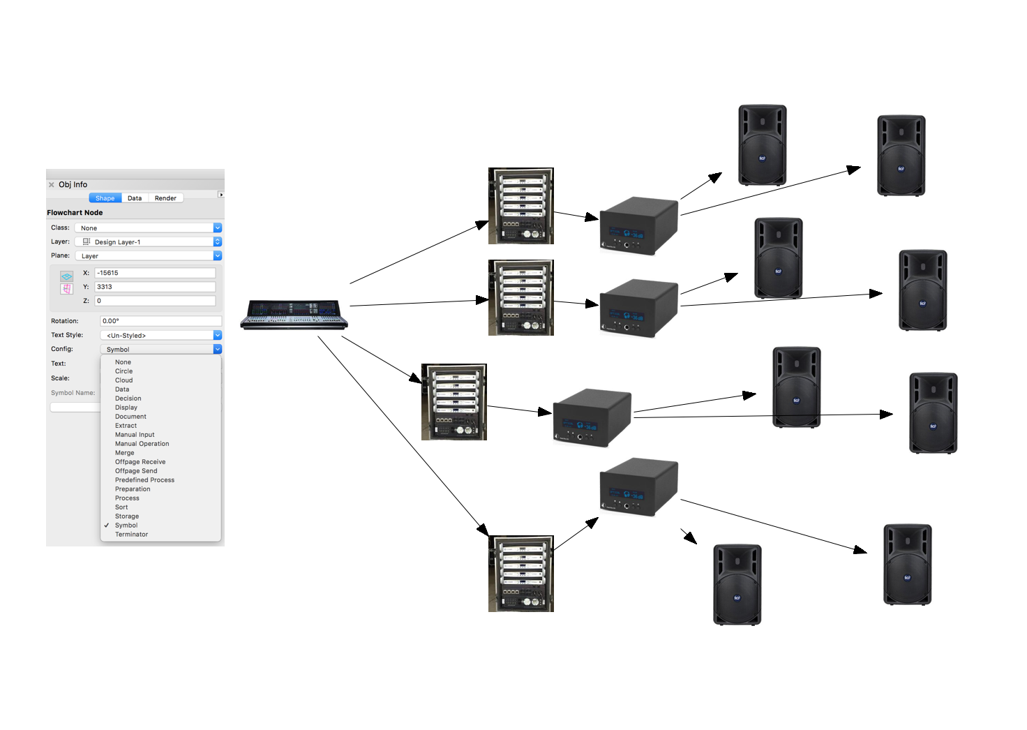
Here's a little hidden secret that you might enjoy.
In fact it's my no 1 Vectorworks 'Easter egg".
Go to the Workspace Editor>Tools>Text and add the Flowchart Node and Flowchart Link to your workspace. It's ideal for schematics!
The great thing is that you can use symbols as the nodes or just use the shapes supplied. Easy-peasy to use. Move one node and the links all 'rubber band' with it, all editable. You can add text etc etc.
In my rather pathetic attempt in the image I enclose, (sorry I'm a LD) the pictures are symbols and I've just linked them into the flowchart. So Vectorworks is Definitely the way to go, you'll never get bored only amazed!
Cheers,
Peter
-
5
-
 1
1
-
23 minutes ago, Kevin McAllister said:
The Surface Studio looks very good. It's a shame Autodesk are part of it and not us:
"3D modeling with AutoCAD (i7 models only)"
Cheers,
Peter
-
Hello,
If you make an image based texture, add a transparent mask. In the example I will post I used the Tiles transparency and then square shape.
The screens were extrudes with a black fill so that the transparent squares looked at the black extrude.
Cheers,
Peter
-
2
-
Change label color with light
in Entertainment
Posted
Hello mreadshaw,
Yes you can use the colour field of a lighting device to change the colour of objects in a particular class. This could mean that for example the channel field which is in the Lighting>Label>Channel class can reflect the gel colour of the instrument. You do this is the File>Document Settings>Spotlight Preferences.
However it appears this is not working in 2018 and 2017. The enclosed snapshot is 2016.
I have filed a bug report.
Cheers,
Peter