


mjm
-
Posts
1,275 -
Joined
-
Last visited
Content Type
Profiles
Forums
Events
Articles
Marionette
Store
Posts posted by mjm
-
-
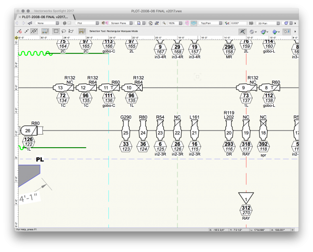
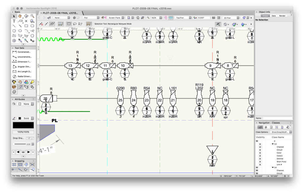
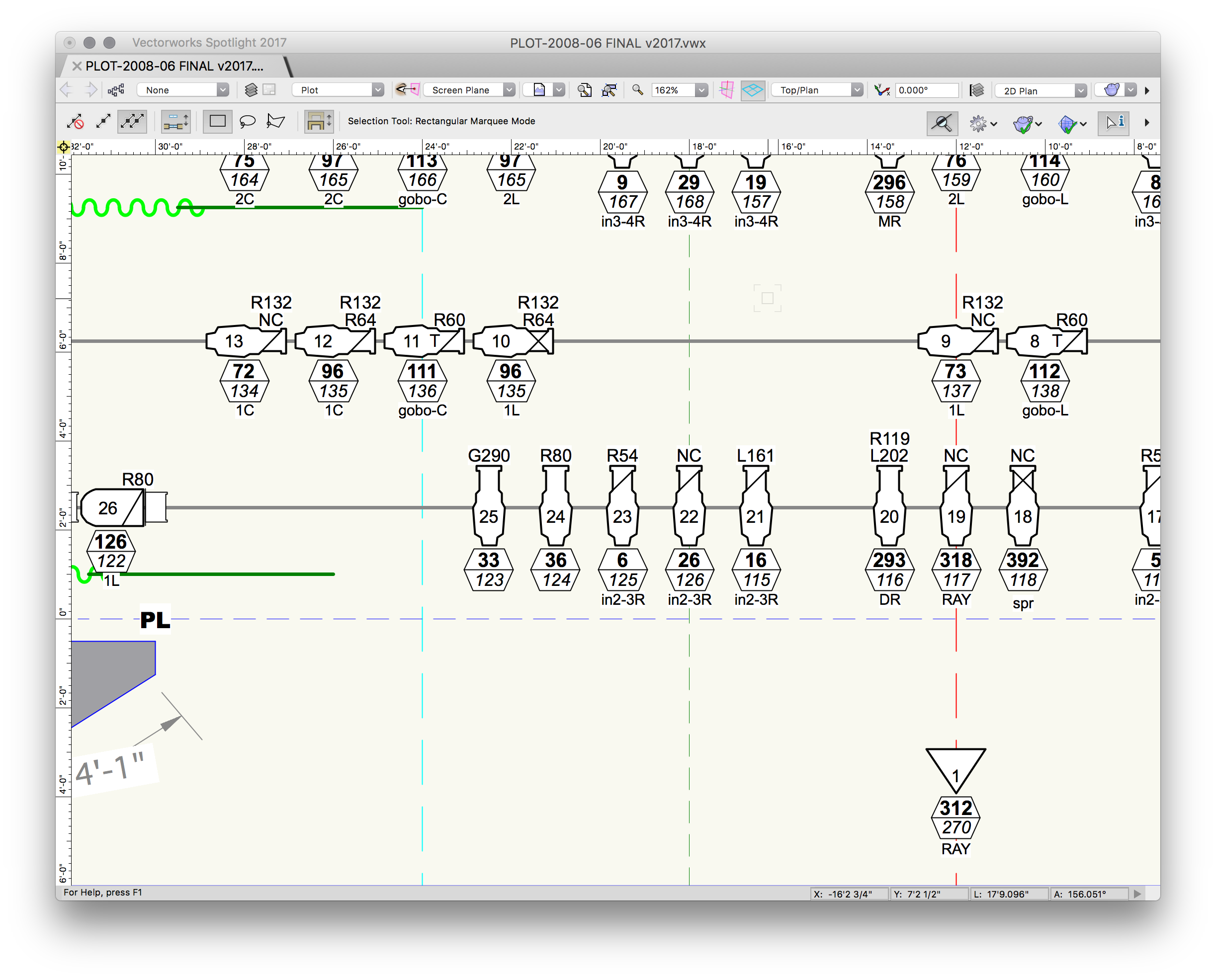
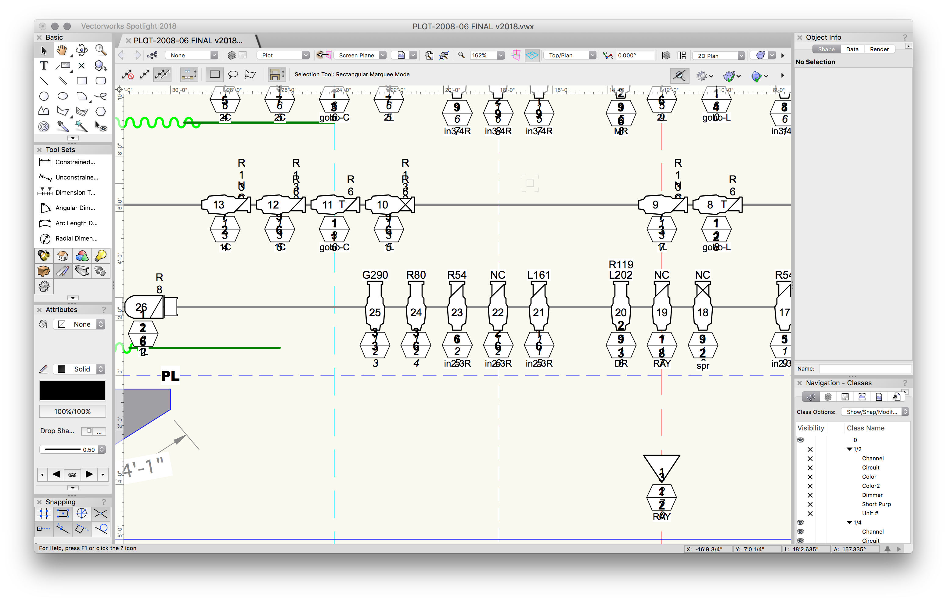
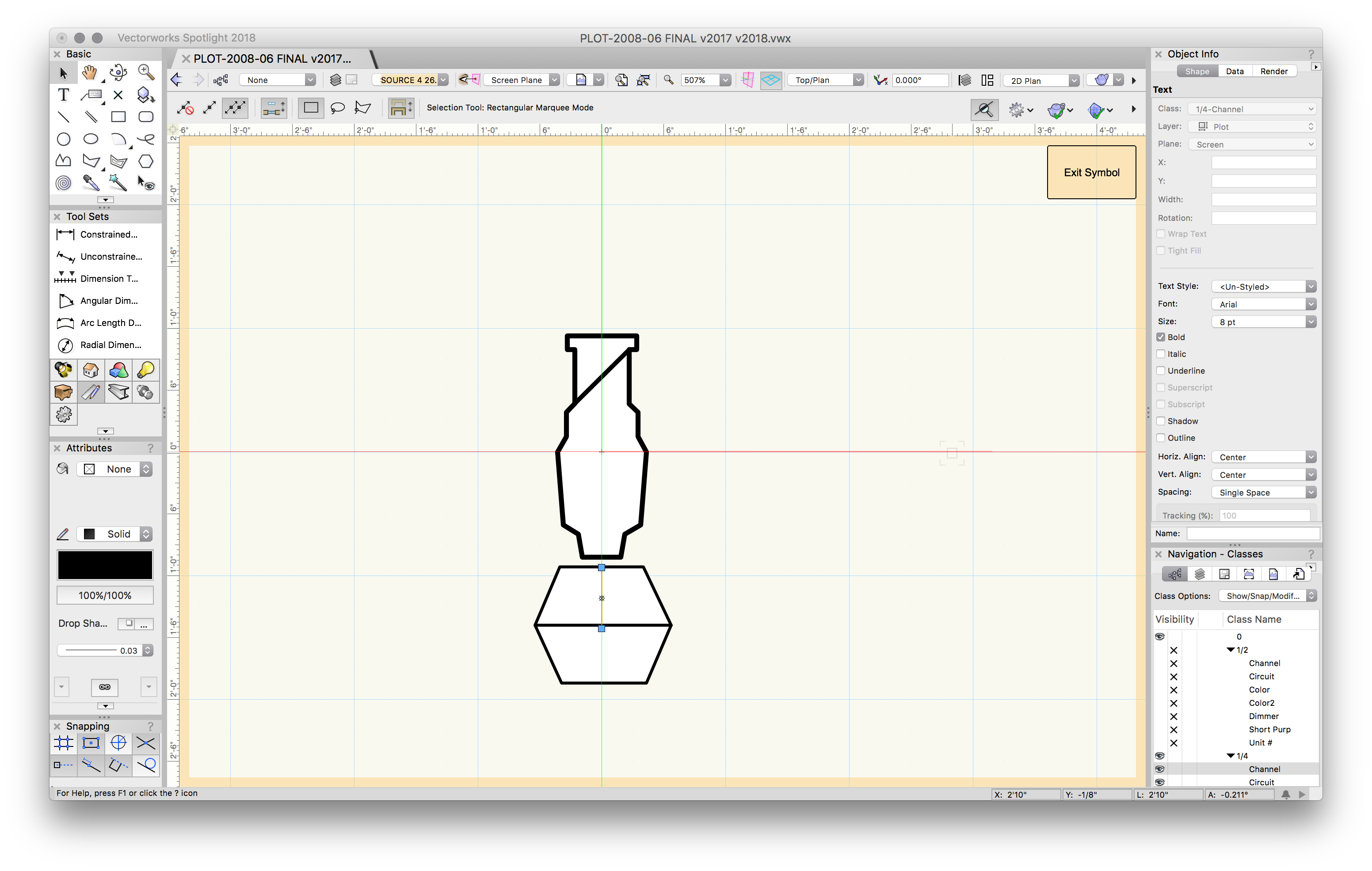
As one can see, 2018's import function seems to corrupt the text layout. Far as I can make out, there's no fix in 2018 possible.
Intriguingly, 2017 has no trouble. I am importing from a VW 2008 file.
Thoughts? Fixes?
Thanks
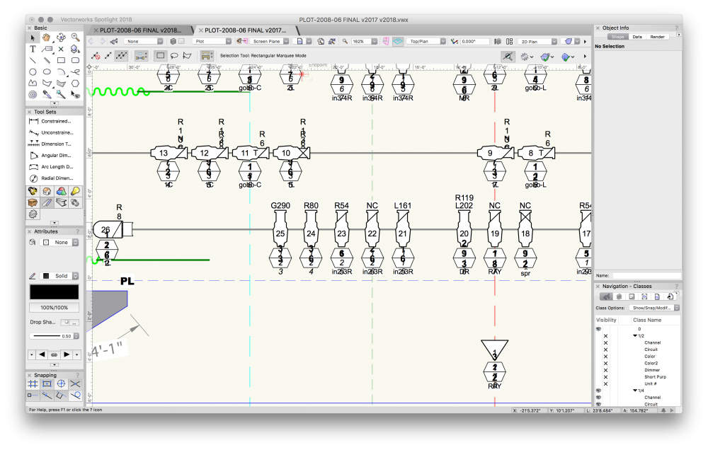
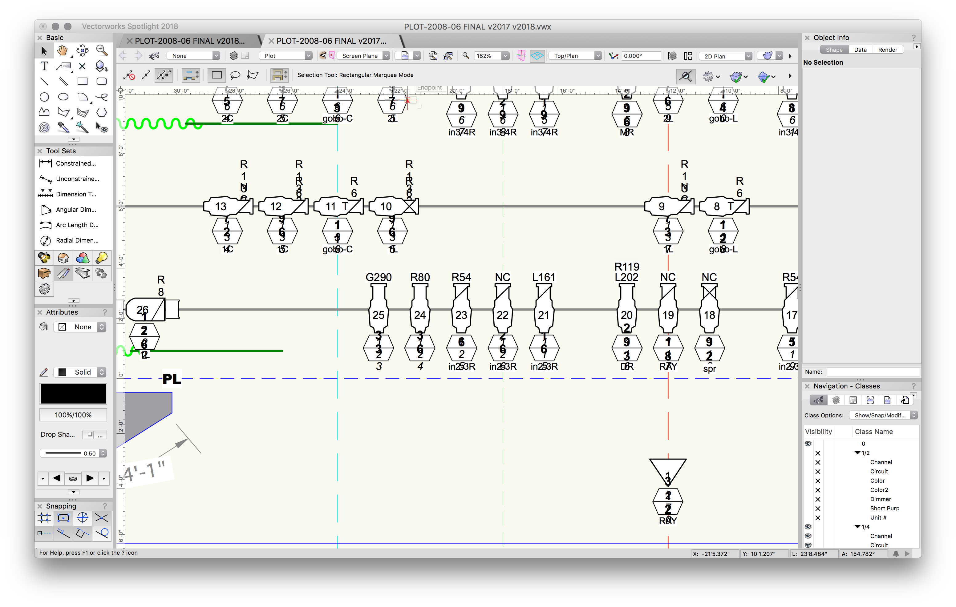
PS; oh yes, the third screenshot? that's from the correct v2017, saved, then opened in v2018. Why does it fail?
So, when I break a fixture symbol down to a group, ungroup, then select text objects, they're all wrapped. There any way this can be globally adjusted within the symbol? All PIO fields are greyed-out

-
When I have these concerns it's generally to protect my assets generated around the lighting, such as scenery, props, architecture. In such cases, I usually provide that info as a layer in PDF form or otherwise flatten the content.
-
6 hours ago, markdd said:
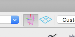
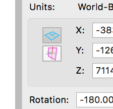
The first thing to say is that the Z height of the instrument is the correct height so use that. The ruler will change depending on the view and its relationship to either the active or any specific working plane currently active. Its a tricky concept to explain and always seems to come down to which one of these buttons is currently selected.
It also looks confusing if you are looking at an Isometric 3D view, ie not Top, Front, Left, Right etc.
If you are dragging instruments to change their height, then I advise you to do this in a non isometric view (Top, Front, Left, Right etc.) with Screen Plane active. That way the instrument will only move relative to the screen in front of you. To be honest, if you know by how far, the best way to move instruments is by using the Move 3d menu command. However, if you are in screen plane then all the other tools for moving and distribution objects will work well too.
The only way to really understand this is to make and save a couple of working planes. For instance, if I am working on a raked stage, then I will make and save a special working plane aligned to the rake. If you have many levels to your set, then you may want to create working planes based on some of these levels as well. Where that is useful is when you need to know the height of an instrument in relation to a particular height of your raked stage or set, then make the relevant working plane active and then highlight the box with the pink grid and the Z height will display the height of the instrument (or any other 3d object for the matter) in relation to the working plane that is currently active.
Phew! I hope that helps!
Mark: Super helpful on the working planes pro tip. Thank you
-
Yes, thanks. But how irritating to have to fiddle around instead of making progress and getting the job done.
-
I am actually experiencing this problem with sheet layer viewports right now. Even for light renders 2018 is failing with some regularity in Viewport renders. not very complex scenes, with relatively few light sources.
-
with Photoshop—Select: Color Range…
should get you very close very quickly.
In VWX—I wouldn't bother trying.
Attached is a two minute exercise in PS color selection and cropping.
The selection by Color Range took a minute or so, as did the crop to get rid of orange square/blue selection handles captured in screenshot.
-
I continue having this issue sporadically. Sometimes opening a different file seems to reset something, so when I return to the file in questions, the OIP is restored to normal.
-
This is terrifically exciting to me.
@JimW: Any idea when this will be delivered?
-
1 hour ago, Andy Broomell said:
Now what I do is immediately hit Cmd+X to "Cut," then click where I want and Cmd+V to Paste.
Funny the workflows we internalize…
I am occasionally fooling around wih the latest A/C for Mac. I am so very very lost in that world.
-
exactly.
-
^ What Andy says. Easy, scalable (yay!!!) Self-illuminating if you desire (or not). If you've never made one before, after creation VW will by default deposit the Image Prop at the drawing's 0,0 position (first few times this made me just a tiny bit crazy. No idea why I am not prompted, after generation, to place it where desired, or why no pref for that).
-
Josh: My method is essentially same as yours. I have been doing it this way because I haven't taken the time to learn Plot Model View yet, and the current projects have so many positions my head explodes just thinking about it. However, where I feel this method fails me is in creating renders with the plot I am drawing. Any insight on ways you work around that efficiently would be gartefully received.
-
Just now, Kaare Baekgaard said:
I restarted, but it did not fix the issue, alas.
First, let me say (as I did not in the first post) I do feel your pain. And lucky that gremlin has not raised it's head since. Hmm—can you send that file to JimW so enhineering can have a looksee?
-
48 minutes ago, Kaare Baekgaard said:
The OIP randomly ceases to display information about selected objects.
Is anyone else getting this?
Please inform me on how to return to SP1 fast with service select – I am too busy to battle with this problem.
Regards
Hello Kaare; I wrote about this a bit ago, shortly after installing VWX 2018 SP 2. A restart seemed to have fixed the issue. @JimWasked me to send a file if reproducable, but happily, no joy there—so far.
-
3 hours ago, JustinVH said:
Hello all,
Thank you for your responses so far. I failed to qualify my initial question properly and I apologize. I am one of the content developers for Spotlight at Vectorworks and I have begun creating a new library of for the PixelFLEX line of products. I am just looking for some user feedback as to the preferred type of symbol for LED panels regarding simple 2D extruded rectangles vs. a more accurate 3D model showing connection points, handles and input sources. As I am not designing for the field nearly as much as designers using Spotlight I just would like some ideas to gain a better perspective on how the resources will be used while drafting and rendering. Thank you.
I wonder why both approaches simultaneously wouldn't be considered: Simple 2D autohybrid for the 2D plan and a more complex 3D object for those usages (I do second the notion of options for complex vs simple 3D as well).
-
So…not quite the moment to invest in it yet.
Appreciate the detailed summary.
-
Dang that's good. And how you evaluate Keyshot at this time?
-
-
See attached movie. Working along, all seemed well, then, BOOM: can't select anything and have it represented in the OIP!
Other editing can take place: moving, deleting, etc.
-
Thanks Mark
-
-
>> another fast-ish route turns out to be:
• draw the poly shape
• convert to nurbs surface, adding as much U / V / Weight as desired (3 is a good start)
• if bend is specific height, add 3D locus over corner at desired height
• move vertice to locus
• shell result to desired thickness
-
Hating the chime
-
True, except the bend tool doesnt get you where you're going —yet.


Earlier version VW Import woes
in Entertainment
Posted
Thanks Mark; I see how I could have been clearer & so have edited the post to reflect the originating SW.