


drmdzh
-
Posts
148 -
Joined
-
Last visited
Content Type
Profiles
Forums
Events
Articles
Marionette
Store
Posts posted by drmdzh
-
-
I'm trying to add a Technical Director field to a title block. In Manage Project Data, I add a new custom field, and make sure Display checkmark is on. When I go back to edit the title block so I can link the field, the text is not showing anywhere on my sheet layer, so I can't link it. I only seem to be able to edit and link text that is already in the title block I was editing.
What step am I missing?
-
Thank you!
-
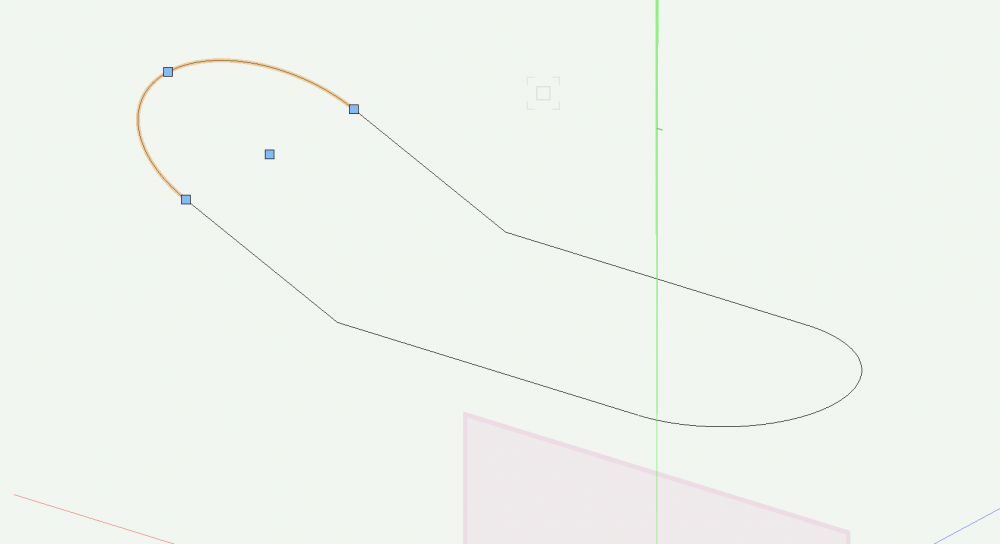
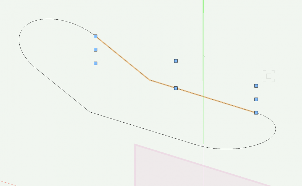
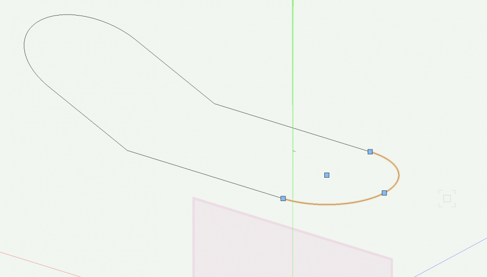
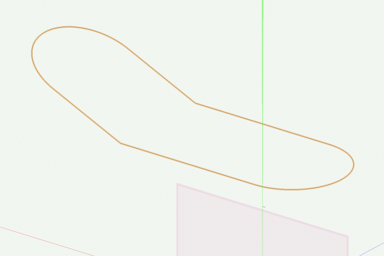
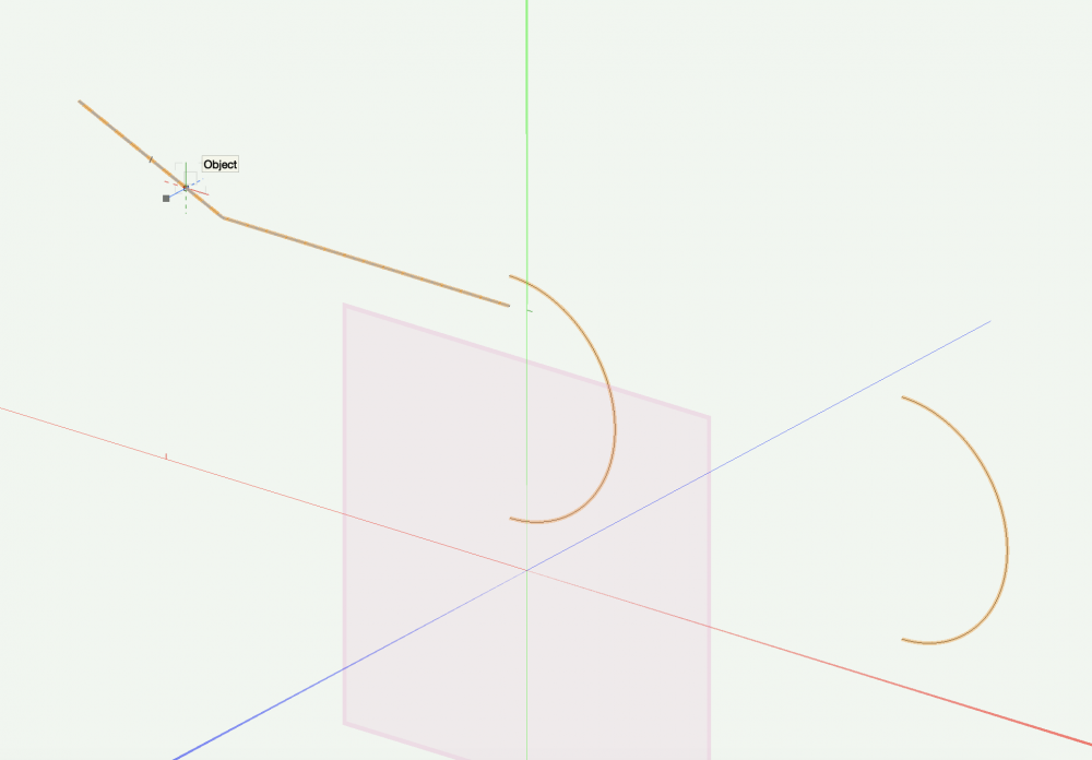
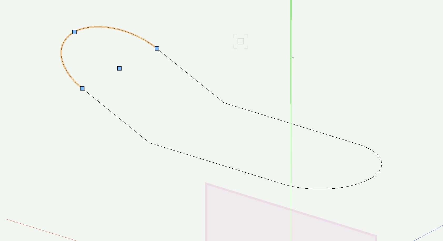
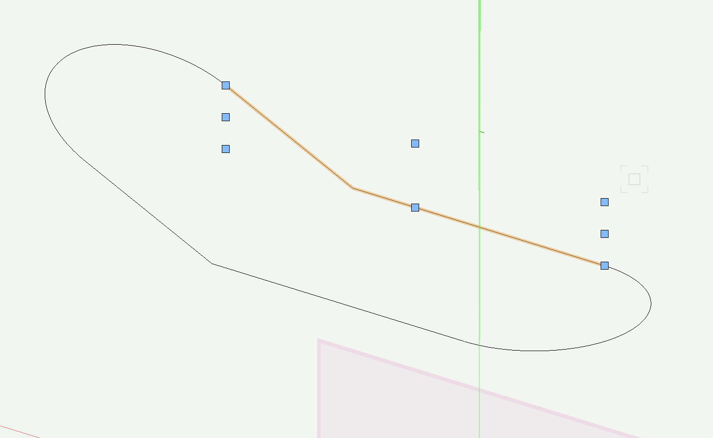
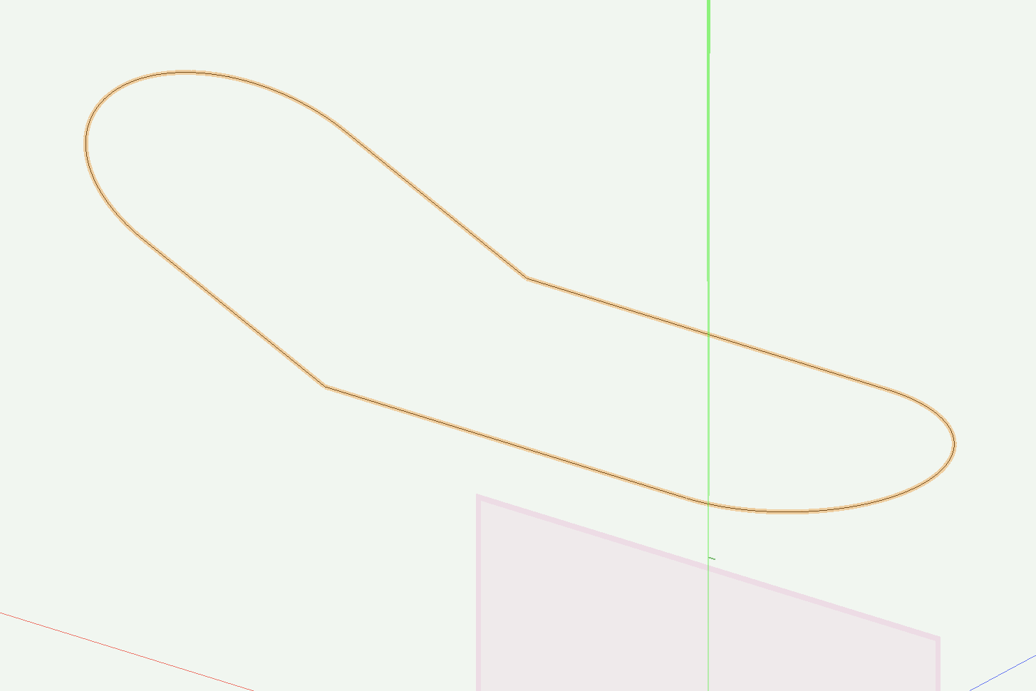
I'm trying to compose a few lines in order to create a path to extrude along for the rim of a bath. I have done this in previous versions but upgraded to 22, and now when I try to compose, the different lines move about and don't compose. These are crated using arc tool and 2D polygon tool, but tried with nurbs curves with similar results.
-
OK, thanks. Yes, it is preventing others from even opening it.
-
I'm using the student version (I am faculty, so I teach what. they learn on) - but it never did this to me before. I have sent pdfs all the time.
-
I just published a set of plans and sent them to my TD. He can't open them as they are password protected. I can't see any setting anywhere in the publish dialogue that I can turn off to unlock them. I opened the PDF in adobe to try to remove protection - but apparently I don't know the password either! (I tried my computer password, keychain password and vwx sign-in password).
Help! Why is vwx password protecting my documents, and how can I stop this?
thanks
-
I created a hanging position (2" pipe) - object info palette says "Hanging Position".
Using the Lighting Instrument Tool to drop instruments in, there's nothing I can do to get the instrument to attach to the pipe, always comes in a z=0.
I googled for the answer, but nothing I find is vwx 2020. The vwx tutorial says what I am doing is correct, it should work.
In the instrument info palette, it says Position: Pipe 1 (which is correct), but it is NOT on the pipe, it's 10' below it.
I have restarted.
I have tried "Attach to rigging object".
I also moved the instrument in 3D to "attach" it to the pipe, and then when I drag-copy the instrument, the new instrument is at z=0 again.
How do I get this to work?
VWX 2020
Macbook Pro 10.15.7
Thanks.
-
I am trying to get the project file functionality to work so that I can share a file between me and a couple of my students so that they can work on the file while I oversee it.
I uploaded the file to Google Drive and created a vwxp file. Shared the google drive folder and the vwxp file with my students. They have managed to open the file, edit it and then "saved and commit". However, when I then open the file I am not seeing any of the changes that are being made, it is the same as when I uploaded it.
I've walked through this: http://app-help.vectorworks.net/2017/eng/VW2017_Guide/ProjectSharing/Sharing_a_Project_File.htm#XREF_58424_Sharing_a_Project
and this http://app-help.vectorworks.net/2017/eng/VW2017_Guide/ProjectSharing/Creating_and_Editing_a_Working_File.htm#XREF_41849_Creating_and
several times, but I can't see what I am doing wrong.
This is supposed to work, yes? We are all supposed to be able to edit the file through google drive?
Thanks.
-
Thank you! Never turned it off before, so I had no idea how to turn it on! got it.
-
I think I mis-typed a key command, but all of a sudden my design layers do not rotate together. I have the theater on one layer and my set on another but when I change the view, either by Flyover or View dropdown, only the currently active layer rotates. How do I make them rotate together again?
Thanks!
-
My student license expired and I requested an extension. How long does it take to get one?
Thanks.
(Projects due very soon!)
-
A student of mine built a 3D model but once she added a few lighting instruments, the model disappeared - in any render setting, in any view. We deleted the lights, which seemed to cause the problems. You can see the model when zooming in or out, but it immediately disappears when not zooming.
Is this a corrupt file, or is something else going on?
Thanks.
-
Thanks all!
-
On 11/29/2016 at 0:24 PM, markdd said:
Sadly with shutters and gobos you can't soften as in real life. I go to photoshop and blur gobo textures there. This would be a really great enhancement to to Spotlight. The ability to "add frost" would also be very very useful.
How do you export the gobo in order to work with it in photoshop. Thanks.
-
 1
1
-
-
oh! thank you so much for letting me know, now I can stop fighting the program!
Can one use anything with an alpha channel as a gobo texture?
-
I'm changing the beam angle in the "Edit Light" menu, (Field angle = 34; Beam angle = 16) and the gobo pattern is still super sharp, does not change when I adjust beam angle.. Not sure what's going on.
-
How do you soft focus lighting instruments? I thought is was using beam and spread, but they are greyed out in the instrument info palette.
-
OK, follow up question: How do you do a plan view cut at 3' high of a wall at an angle? Or even a full groundplan cut at 3'? When i am in front view and click "Section viewport" it reverts to top/plan view.
Thanks.
-
-
So are you saying that in Top/Plan in the design layer, you create a section viewport, but instead of cutting through the object, you run the section line parallel to the object to create a front elevation?
-
As a scenic designer, rarely do I have walls parallel or at 90 to the proscenium. So what is the best way to create a plate of elevations (front, section and plan views?)
When creating a section I know I can do it from the top/plan view.
Is there a way to rotate the view of the viewport other than entering degrees in the dialogue box? I tried set working plane, but that didn't work. But many times I might have walls at "random" angles - (52.36 or whatever). Seems like there must be a better way?
Seems like this should be a basic function of VW - creating viewports from a 3D model, but this seems not to be addressed very well.
thanks.,
-
Thank you very much!
-
I am looking for the answer to an older question and in a thread I found someone linked to a thread: https://techboard.vectorworks.net/ubbthreads.php?ubb=showflat&Number=221341
but every time I click on that link it takes me to the "We've Moved" page, and I can't get to the thread I need!
-
OK, sorry, I fixed it. I got Custom View to work - but second question, I can't take a section of it now? How do I get a section of something on an angle.
Thanks for your patience!

Soft goods - scrim
in Entertainment
Posted
I used to use the softgoods tool to create scrim - 3D options to scrim, the set pleat width and pleat depth to 0".
Now, however, when I set the depth and width, they default to 1'0" for width, and 2" for depth. How do you go about creating a flat scrim now?