

Horst M.
-
Posts
393 -
Joined
-
Last visited
Content Type
Profiles
Forums
Events
Articles
Marionette
Store
Everything posted by Horst M.
-
That's a very cool Idea and Script! On my Macbook Pro with Nvidia Gforce 9400M: Open GL: 0,3 Fast RW: 0,6 Fast RW w/Shadows: 0,7 FQRW: 0,8 CRW: 0,8 Fast Radiosity: 1,1 FQ Radiosity: 19,4 Custom Radiosity: 19,3 On my Macbook Pro with Nvidia Gforce 9600M GT: Open GL: 0,3 Fast RW: 0,5 Fast RW w/Shadows: 0,6 FQRW: 0,7 CRW: 0,7 Fast Radiosity: 1,0 FQ Radiosity: 19,4 Custom Radiosity: 19,1
-
There is a lot of stuff in the knowledgebase http://kbase.vectorworks.net/search/viewport http://kbase.vectorworks.net/questions/578/Viewport+Tips+%26+Tricks Also the help section of VW is.?... helpful! (in this case..) Actually the creation of Viewports is normally very easy and fast. draw a rectangle (or whatever shape) arround the elements you like to see in your viewport, goto Menu View-->create Viewport set the desiered scale name and so on in the upcomming window, and hit OK. I the case you describe, it sounds like the Sacle is set too high. or the View of your Monitor is has to zoom in a lot. To adjust this, To enlarge the viewport to the size of the Window on your screen, select it and hit CMD and 6 (on the apple). To change the Scale, select it, and change the Scale in the Object Info Palette. Horst M.
-
Hallo David, Since I use VW I couldn't figure out, which Resolution the resoultion setting in the Document Preferences effects. ??? The resolution for Sheet Layers and Design Layers are set through the Nav. Palette as michaelk writes. If you use Export Image File, you can set the resolution for the exported image in the Infopalette as shown in the attachment. Sometimes when the Infopalette opens, the Reolution Field is greyed out and can't be changed, then you must switch arround a few times between the 5 modes in the Export Area (no idea why, but check with Preview what will be rendered), then you should be able to type in the resolution you want. You will see the change in the Pixel Dimensions field below the Resolution field. After that you can save the image. Horst M.
-
Try rendering the image in a higher resolution, then the the Moire effect on the roof surface should disappear or at least decrease.
-
Hi, Thanks for the Input. Some of the first results attached. I'm still working on the Structure, walls, curtains, Ceiling and so on But it is a already helpfull to figure out the Ligthing Positions.
-
Thank you so much Pat. Should be the right Moment to Start with Vectorscript. I let you know when I get Stuck. I haven't written programms since the days of the Z80 and some Assembler Routines for Hardware under DOS. Stoneage...
-
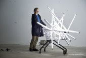
Hallo, For a lighting Object I want to do some renderings to check different lighting solutions. The plans of the obect are 2d. Basically the object will be built of several hundred pipes. There are 3 different kind of pipes with the diameters of 12, 15 and 18cm, represented by circles in the 2d plan I would like to selct the circles with the same diameter, and replace them by symbols, with a 3d Part, the extruded and textured Pipe, and a 2d Part with the Circle. I can select the different circles (there are between 198 and 420 for each diameter; 906 in total) with the custom selection tool. How can I replace them with a Symbol?
-
I found, that the Door- the Window- and specially all this Stair PIO's cause these Kind of Problems in renderings. What I find even worse is the case, that a Fillet on an Extrude gets the Texture applied 90? rotated to the texture on Surface of the extrude... See image attached. (FQ-RW) Who needs that and for what? I spent a lot of time, finding workarrounds for creapy behavior of PIO's Stair Tools and bugs in Basic tools like Extrude alongpath.....
-
http://www.aladdin.com/support/hasp/hasp4/enduser.aspx I've a HASP4
-
I find ist absolutely frightening, that VW 2009 and 2010 are sold (and somehow seen to run) as compatible with Snow Leopard, and if I go to get the Dongle Driver on the manufacturers Website they explicitely list Snow Leopard under imcompatible OS's! I can't find a compatible driver for Snow Leoard on the Website of Aladin ! What shall we do now? Update to Snow Leopard and hope...
-
Jeremy, if the effect of the dasehd Lines in the rendering is really caused by the dashed Style of the Basic 2d Polygons for the Extrudes, I see that as a bug!, because the line Styles of the resulting Extrudes in your cabinet are solid!
-

Modeling Buildings in Complex Urban Planning Context
Horst M. replied to stmlandplan's topic in General Discussion
The big part of the work for the apporach you discribe under Point 2 will be to get the Fotos of the buildings, and to prepare them to be used as Wallpapers for your the massing models. I think with the image prop idea its the same. Once you have the Fotos cut, rectified, stiched and colorcorrected that they visually fit together in your Scene, you can use the new Add Decal Tool to place the Fotos on the surfaces of your Models. I've recetly tried that for a Venue with a complex Steel Structure, that is very detailed and I'm still not where I want to be. I thought of using simple extrudes/Walls and place Fotos of the real Wall Sections onto these Extrudes, but the work that goes in the Preparation of the Fotos is imense, and needs someone who is used to Photoshop. (...lets say more used than I'm! :-). A nice example for this Kind of work can be found here: http://www.maxon.net/en/news/singleview-default/article/3d-digital-model-of-hamburg-germany.html -
Hi, I did some Renderings, and can't reproduce the dashed effect, but I opened your Cabinet Symbol, and found that you constructed your Cabinet with the Multiple Extrude Tool (which I don't like very much, because I found that it created Objects that don't snap very well) and that the basic 2d Polygons for these Extrudes are drawn with with a dashed Line Style! I'm very curious, what happens with your rendering, when you Edit the 2d polygons of the Multiple Extrudes and set the lines Style to Solid....
-
Hi J, I still don't think, that the vertical jagged lines are are caused by the dpi setting, because the two clours are rendered with very precise edges, and they are bigger than 1 Pixel. Could you post a File with just one Cabinett door inside. I'm almost shure, there must be something with the geometry or RW that causes this effect. To finalise your Image, brighten the whole thing up, or just certain Areas, I would like to suggest using Photoshop or Gimp. Less waiting and more possibities, and you could also get rid of those Vertical dashed Lines as well. :-) I use Photoshop Elements, and find it not too complicated, and for colour-, brightnesscorrection, and some makeup its fine, and also cheap enough.
-
I've seen effects like the fat Vertical dashed Line in renderings, when I once in while have by accident duplicate objects overlapping each other in the same place. Then one is textured, and the other isn't. The rendering of such objects sometimes look like the borders close to the windows in the cabinets. The other possibility is, that you could check if Anti Alias ist selectetd in the CRW Options. By the way, what did you do in the end to get your Ceiling in the shown colour?
-
Once you have the Bell as a Solid, like in Rays File, you can also use the Shell tool to get the Hollow you want for your Lamp.
-
Hi Jeremy. I feel guilty. 3.5 hours is far more patience than I have. The renderings above, with Final gather at 30% and Ray Tracing at 8 refrations took about 3-5 minutes to render. Final Quality Renderworks takes about 1 minute. both on my Mackbook Pro. I think Rebnderworks crasehd in your case. I will try later on if the extreme slowness could be caused by Line lights, which seem to be part of your Scene.
-
Hallo, You get a much more realistic look of your Ceiling if you enable Final Gather. For the final renderings I also enable "Use Ray tracing" and set the refractions to 4 or 8. If you keep the Final Gather accuracy low (like 30% to 50%), you still have acceptable render times (depending on your patience..). The light sources for the attached renderings are 6 Point lights (like bulbs) 0.3m (1ft) below the ceiling. The ceiling and the walls have the Stucco_medium_White texture, and receive a lot of yellow light, because the reflectivity of the Floor (a carpet of nature colored sisal) is set too high, but you can see the effect of the Final Gather for the ceiling. What Ray and Jonathan write is correct, because if you have the lights close to the ceiling, the ceiling gets most of its ilumination from the reflections caused by the walls, the floor and the furniture, therefore it is really darker (but never dark grey!), but we adapt that and "see" it as bright as the walls. That is what Final Gather adds to the Renderings.
-
Hi, You also think about adding Text as image resources, or decals on surfaces of singnposts may be the easiest Way is to add text in a Video editor, like iMovie, Finalcut and so on, with these Programms you can also add Music, and spoken explanations.
-
Thanks fo the help.. I knew it's me missing something simple :-(( @jonathan: may be you are right with the open GL Statement. just... never saw something like this in open GL in C4d. (for example...) Horst M.
-
Hallo together The question reminded me that there is a Variable Radius section in the Fillet tool. I hope I'm not totaly missunderstanding the whole thread, but with this Tool, and some patience in fidling with the settings I got a result that looks pretty much like the the upper left Corner of the Cabinet's Foto. The rendering looks Ok, even though the Fillet tool behaves a little bit Vectorworksi ;-) , and creates some surprising polygons on the surface... Horst M.
-
Hallo, I'm stuck with something that I thought should be simple. I want to paint a Brick Wall in a Color. So I created a Renderworks texture with a Plain Color, and applied the "Textured Brick" Shader in the Bump Channel. As long as I'm in the Edit Texture Resource Mode, the renderd Wall looks fine. When I leave the Edit Mode, the Brick structure gets distorted. I tried all the settings of the Texture shader, without getting rid of the distortion :-( Any Idea Why?
-
Hi Nick, If you want to create something like a Gorund support, you need (in real live) Cornerbloks, like michaelk mentioned. (image attached) They can't be made with the VW Truss tool. For the Shown example I used downloaded Elements from Prolyte. You can also download the Symbols from Eurotruss and others. The Prolyte Symbols come with a Centerline in the Cords, that makes it easy to aliign them in 3d Space. The Eurotruss Elements have round Cords, so you can use the Center of the Cords to snap the Elements together. Eurotruss and others are avaliable in the VW library, but the Elements are Hybrid, and the 2d Part makes it impossible to rotate them in 3d Space, without editiong every Symbol, so I found it easier to just use 3d Symbols imported from the Maufacturers dwg's. If you don't want to construct a real Grund support, and just sketch something that looks somehow like one with the truss tool, it makes sense to align the elements in 2d, and set the z-Hights through the OIP, like bcd suggests, because you dont have good snap Points to align the trusses in 3d Horst M.
-
Hallo Jeff, Sounds as if your client is looking for something like that: http://www.zerofractal.com/fractalreality/ The workflow is, to create the model with VW, Export it to Cinema 4d, and animate the textured model with Unity 3d. The result can be a compiled App. for your Customer, that he can use like a Videogame, to walk through the Virtual Model. http://unity3d.com/gallery/developer-profiles/architecture-and-viz/ZeroFractal I'm pretty shure, that Stuff like this is kind of the next step in Architectural Visualisation. I like VW for modeling, and to render some images, but to use it for a real time Walk through sounds like asking for headache. Also the really nice possibility to export the Model as a Quicktime VR Objekt or Panorama looks like a dead end, if I trust the recent news about Quicktime VR. :-(
-
There are two independent Problems in James Example Handrail experiment: 1. The Connection of the 2nd and 3rd Segment (see my previous Post) is just impossible! Thats not a bug! There is no way to cut the EAP's of the two Segments in a way to achieve a smooth transition. (Assumption to be disproved :-) 2. The twisted EAP in the 2nd (middle) Segment caught my interest I did some Experiments with a surprising result: If you do a EAP with a simple Profile (rectangle) on a Nurbs Curve in Y Direction (just 2 Verticies with different Z hights) the Result is twsited! If the you use the same Nurbs Curve in X direction, the result is OK! I think this a bug... Files attached