

LJ TMS
-
Posts
178 -
Joined
Content Type
Profiles
Forums
Events
Articles
Marionette
Store
Posts posted by LJ TMS
-
-
4 minutes ago, Wesley Burrows said:
Update: After multiple profanity laden tirades that probably changed my 3 year old daughters life forever. Smashing some inanimate objects, and pacing around like a psychopath, I discovered if I save in a 3D view (num pad 5 in this case) and re-open it holds the correct rotations. If I save in Top/Plan, it all goes to hell. what. the. actual. F.
Lol, wow I hate stuff like that! Well at least you found an easy enough workaround.
I just checked my test file and I'm not seeing that issue regardless what view I save in. I'd definitely forward that to VW so they can take a look.
-
Damn, that sounds frustrating! I haven't fully moved over to VW2019 yet, but I just tried adding a few truss and fixtures to a blank file, made a DLVP & rotated, saved & reopened it, and didn't see any problems.
I'd file a report with VW and send them your file. They may find a bug that can be fixed.
Occasionally when I come across some weirdness like that, I try and copy over the offending parts of the model into a new file and see if my issue still occurs. If it doesn't, I copy the contents of each design layer one by one into a new file. You won't be able to copy sheet layers or viewports between files, so those will need to be recreated. But it least it may be a workaround to your current problem.
-
 1
1
-
-
1 hour ago, Bhel said:
@LJ TMS Are there problems with importing those into Vision though? Ive been reading about these DLVPs that create problems when going into previs because they don't show correctly.
That's correct unfortunately. Vision doesn't understand Spotlight instruments within a DLVP so it converts it all to a mesh. Now that Vectorworks owns Vision, I'm hopeful they'll come up with a method that works for both (either Vision interpret the contents of a DLVP, or VW change it's raked truss solution to something that works with Vision).
-
4 hours ago, Bhel said:
This seems extremely confusing for someone not experienced with years of VWX use 😰. As I literally downloaded VWX for the first time about a week ago aha. Im trying to get myself trained up to take on some small projects.
No worries, this is the place to learn!
4 hours ago, Bhel said:Now why would anyone need to make a plot of an automated rig with hanging positions or scenery at different angles or heights? If I am building someone a plot in my mind I just need to give a view and close ups of the hanging position/pod so they can accurately build it. They wouldn't need to see its various positions changes, just what the structure and fixture placement layout is. Right..? I feel like people that are trying to show concept renders tend to use C4D or illustrator for inaccurate 3D concepts.
For the raked truss scenario I suppose the same question could be asked as I think about it. For a plot they don't need to see the truss raked even if that will be its final flown orientation. And thinking of the geometry of that scenario... If I were to do all this DLVP work and angle truss so the front is higher than the back wouldn't that make the truss appear to be shorter and the lights more condensed on a top view for a plot? In that case I wouldn't want to rake the truss. Correct me here because I have no idea. #greenhorn.
This may be highly dependent on what industry you work in and what type of events you're drawing. I work with a wide variety of entertainment lighting and generally speaking, events like corporate, weddings, and traditional theater wouldn't utilize much angled lighting/truss. Whereas events like concerts, festivals, tours, etc can use a lot of lighting & structures at various 'non-flat' angles. For these type of events, you really want to 3D model what the end result will look like. Not only to show the client with renderings, but also to properly convey the construction and layout to the production crew. Also consider if you were building an event in a constrained amount of space, and/or have different elements close to each other, you need to make sure it's all going to fit, even at funky angles.
The beauty of using DLVP's is you end up with a definition layer that you can use for nice 2D top/plan views of raked truss as though it was flat for use in plots, and the DLVP object for use with 3D renderings and front/side views.
For renders, Vectorworks and/or Vision can work very well to illustrate your concepts! They both have their quirks and shortcomings (like any software), but it's perfectly achievable without using any other software.
-
14 hours ago, scottmoore said:
Agreed. That said, and I have said this before, DLVPs do offer quite a lot of flexibility beyond simply raking a truss. Let’s say you have some lighting pods that are automated at different trims and different angles throughout an event. No problem. Make duplicates of your initial DLVP, class each seaparately and move/rake to your heart’s content. Have a piece of moving scenery that travels about on stage? Same thing. DLVP’s are really quite versatile and those are just two examples of uses that could not be accomplished by simply rotating geometry.
I've used DLVP's for multiple lighting positions/scenes, but I've never used them for scenery. If I had moving scenery, I would generally use classes and/or layers. What would you consider the benefit to using DLVP's in that instance?
14 hours ago, scottmoore said:Clunky? Yeah probably
As far as clunky, I think I have more of a problem with the way 'Create Plot & Model View' menu command works than I do with the overall concept.
As an example...
I have truss & fixtures sitting on 'Layer 1' that I decide I want to create a DLVP of. I run 'Create Plot & Model View' and it asks me to name a new definition layer and select the model layer (which can't be the the design layer I'm on, so let's say 'Layer 2'). I now have a newly created definition layer, a DLVP on the 'Layer 1', and a DLVP on the 'Layer 2'.
I realize the solution after I run this is to delete one of the DLVP objects and get my classes and visibilities setup to work with. But I think many users (especially those inexperienced with the command) would find the end result confusing and would probably be hesitant to delete one of those DLVP's (since they'd wonder why there was a duplicate in the first place and probably think it necessary for some reason).
I don't understand why it either (a) it doesn't allow me to select the current layer as the the model layer and place the DLVP there only, or (b) if it's going to force me to select another layer for the model layer, why it's putting a duplicate of the DLVP on the active layer.
14 hours ago, scottmoore said:my solution to avoid the clunky aspect is to do the following in my template file:
- I have ten design layers already set for creating DLVP’s.
- I have ten classes already set up for DLVP’s.
- I have already created the physical viewport for each design layer, assigned it to it’s appropriate class and turned on the “use current class visibilities” option.
For me, all I do is start drawing in the pre-defined layer, go back to my standard drawing layer, turn on the appropriate DLVP class and rotate into position. Done!
Interesting, I've never considered pre-setting up design layers, classes, and viewports to be ready to go for DLVP's in my template, but that's a great idea. Thanks for the tips!
-
20 minutes ago, scottmoore said:
To me, the big selling point of this process is not simply the ability to rake production structures, but that it allows you to print plan views without the raked truss. Avoiding wireframe 3D geometry in a 2D print is a huge deal to me. It also allows you to go back and add to or modify the structure very simply without changing working planes and whatever else.
It took me a while to warm up to DLVP's... it always felt like a clunky solution to the problem. Ideally I'd love to be able to go to a front or side view and rotate truss w/ fixtures and VW just figure it out. But as you said, it's great to have the definition layer for nice 2D top plans for plots.
The big issue for me is that Vision turns DLVP's into mesh (truss & fixtures) with no Spotlight instruments. That means if I want raked truss w/ fixtures, I either (a) can't use DLVP's, (b) can't send to Vision, or (c) need to duplicate my work.
Vision needs the ability to interpret the contents of a DLVP and place it in the position/orientation of the DLVP object. Or VW needs another solution to raked truss that Vision can interpret.
-
1
-
-
On 1/19/2019 at 4:19 PM, Robert Janiak said:
I maked simple plugin for add individual focus point to all selected device by Pan/Tilt angle. Plugin take into account 3D device rotation. It helps me focusing conventional devices like Led Par or Led Bar and speed up my work with Vision. Please ask me if you are interesed in testing it.
I'm interested as well, very cool!
-
Just now, C. Andrew Dunning said:
Thanks for posting this, LJ.
If you remember, EVERY fixture - moving and fixed - was spun around when we opened the file on the 2nd computer.
Your absolutely right Andy, completely forgot about that! So yea, this bug definitely can occur with any type of fixture.
Kevin, I attached the esc file in JIRA (VB-157492) if want to take a look. Although good luck getting the bug to trigger when your trying, lol.
-
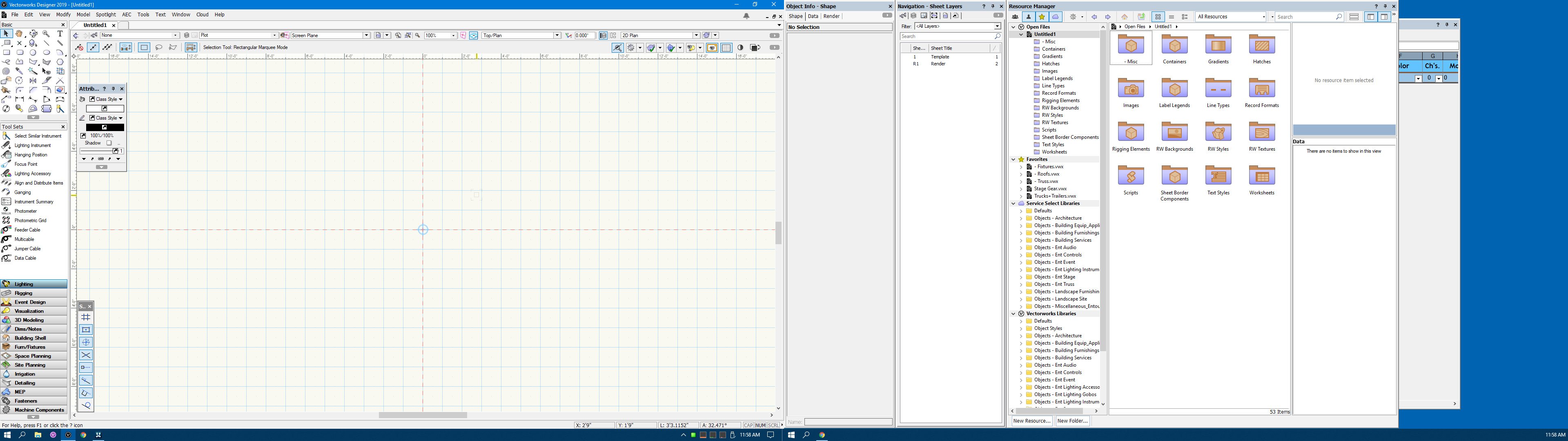
5 minutes ago, bbudzon said:
And while I will pass along the information about controlling smoke machines and multiple cameras, I can already help you with the toolbar size! If you right click the toolbar, you'll get a context menu where you can set whether or not you want tool text beside/below the tool or not shown at all. You can also pick whether or not you want gray scale tool icons. Lastly and arguably most importantly, you can select the tool icon size from this context menu!
This is very cool! I had no idea there was a right-click menu to the toolbar with options. Awesome, thanks!
-
1
-
-
Hey Kevin, thanks for the reply. I don't work with conventionals nearly as often as I used to, but I've had this bug occur with led pars & bars, and I'm pretty sure I've seen it happen to movers as well (although I might be misremembering).
The above example I was using Elation SixPar 200IP's and rotated with 'Set 3D Orientation' in VW (no focus set).
Edit: Also not sure if it matters for this bug, but I always use the 'Export ESC' command (not 'Send to Vision') since I use separate computers for VW & Vision.
-
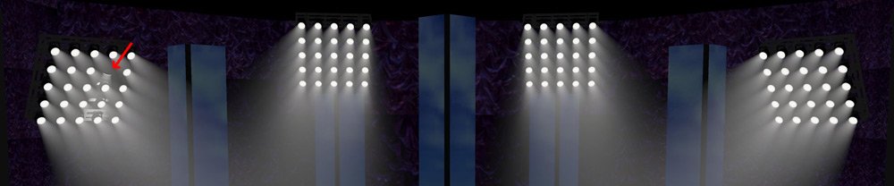
I have issues like this as well. But I think it can be anytime you load (esc or v3s). Unfortunately it's so inconsistent that I've hesitated to file a bug report for something not easily reproducible. Majority of the time reloading will solve the issue, so I mostly just deal with it.
Here's an example of a show from earlier this week (loading the same esc file).
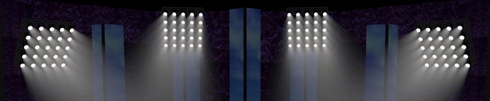
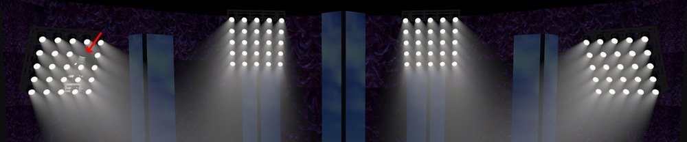
The reason I took these screenshots is the first time I loaded this esc into Vision, two of these fixtures were oriented wrong. I started hunting around of where I messed up before realizing I just needed to reload the esc and it fixed them. After that I reloaded about 2 dozen times trying to get something consistently reproducible and only got the above screenshot once.
Edit: Filed bug VB-157492
-
Most of these questions are better answered by a Vision employee, but I can answer a few...
1 hour ago, zeroInf said:Why the light crosses the wall ? * Screenshot_2.png
In File > Document Preference > Rendering tab (or in the Properties window under 'Globals' dropdown, when ROOT is selected in the Scene Graph), enable Render Shadows.
1 hour ago, zeroInf said:Bloom lens are like big Pixel . why? * Screenshot_4.png
In File > Document Preference > Bloom tab (or in the Properties window under 'Bloom' dropdown, when ROOT is selected in the Scene Graph), adjust the values of Bloom Percentage, Bloom Threshold, & Bloom Lens Strength to get your desired amount of lens bloom.
1 hour ago, zeroInf said:How can i use the tool: - Xfrom (In properties palette )
Xform is used as a way to have truss & fixtures (or scenery) move position or orientation via DMX. It's been a while since I've used it (and it has changed in that time so this is just broad strokes), but basically if you had a truss & fixtures you want to be movable, you would create a new layer in the Scene Graph, and drag and drop the truss mesh and fixtures into the new layer (you can also accomplish this via a separate esc export from VW). Then select that layer, assign it a Xform universe, channel, and use Delta X, Y, Z values (in inches) to where all of it would move to when the DMX value is raised. For example apply the value of 120 to delta Z, and you could move the truss and fixtures up 10' in height. Also note X, Y, Z is relative to it's starting position, not an absolute position to the document origin. Rotation Axis, Delta, & RPM should in theory allow you to rotate it's orientation, although I haven't played with it since it's been redesigned.
Edit: Actually in the example I gave, you would use Delta Y (not Z). Vision has long had their axis named differently than VW (which really should be changed to be identical). X is the same with both VW & Vision, but Y & Z are switched.
-
1
-
-
48 minutes ago, Andy Broomell said:
Using a Design Layer Viewport, as @LJ TMS suggests above in #2, would be how I would approach this, since it allows you to still edit the geometry in an orthographic orientation (un-tilted) which is probably easier.
That's a great point Andy. Making changes to the truss layout or fixture placement after the fact is going to be way easier with method 2 than it will be with method 1. Especially if you decide to rotate that on more than one axis. If you do go with option 1 and need to make changes, you'll want to read up on Working Planes.
-
Yep, you have two options for rotating that...
1.) As Justin mentioned, strip out all the 2d components.
When this is done correctly, symbols will show a little "3" in the bottom right hand corner of the symbol thumbnail in the Resource Manager to indicate the symbol is 3d only (not hybrid). If you think you've deleted everything but still don't see a 3 on a symbol, look at the visibility of your classes because your missing something (like a 2d locus). If any of that truss was drawn with the truss tool, change your view to 3d, select it, and ungroup. It will give you a warning about ungrouping high level objects, select yes (this just means it's no longer an editable plugin object that can be changed in the Object Info Palette). Once everything is 3d only, you can select it all and rotate on any axis.
2. Use Create Plot & Model View.
When you run that command on your selected objects, it will create a Design Layer Viewport (DLV). You'll end up with a single object (almost like a symbol) that can be rotated on any axis. The components of that object (the truss and fixtures you selected when creating it) will end up being on a design layer called the definition layer. Any changes you make on that definition layer will be shown in the DLV. It's a bit confusing at first, especially right after you run the command you'll end up with what looks like a couple duplicates, but it's probably the best way. The DLV can be rotated however you want and that's what you'll use for 3d views & renderings. The Definition Layer will still have a nice top/plan view of the truss & fixtures for use on plots. I usually place the DLV object on the same layer as the rest of my drawing, and assign it a unique class so I can turn it's visibility on/off.
A quick google search led me to this video which should help. I haven't watched it in full, but it should help familiarize to how that command works.
-
2
-
-
1 hour ago, scottmoore said:
Understood on all counts. I suppose the “hope” would be that you wouldn’t be exporting into Vision until all the design and re-design is done. Of course we never live in a perfect world and it may be that Vision will reveal some issues that need to be resolved back on the drawing board. It seems like the quick solution for Nemetschek would be to make the rotations of groups of objects in Vision very simple.
Yea that's always the hope, but I've had far too many instances of major changes that need to be made. I avoid at all costs doing any changes on the Vision side, since any re-export from VW means doing those changes all over again. At the VW Design Summit this week, Vickie Claiborne put it best that VW should always be your show bible. I look at any changes made to a show on the Vision side other than saved views and render settings as wasted time. That is until there is two-way communication between VW/Vision.
1 hour ago, scottmoore said:The way I recall dealing with moving trusses (it’s been several years for me) was to import everything associated with the moving truss at one time before importing anything else and all those items became a “node”. Perhaps it was called something else but you get the idea. Regardless, you could easily grab an entire node and manipulate it. Once I understood that, automation processes were really quite simple; it just required multiple exports from VW > Vision. I am just wondering if that might be a faster workaround if rotation functionality works for entire nodes? Additionally, I don’t recall Vision having really accurate CAD control of any type so I would probably create some dummy markers in VW and export those into Vision to allow for some quick line-ups of rotated objects.
I don't mess with moving trusses all that often, but that was indeed the way in Vision 2 using Transform Nodes. You could do multiple exports to separate out the truss positions from each other. Or since Vision groups all geometry together that has the same fill color or texture, you could give each truss a slightly different & unique color so they are separate meshes in the Scene Graph. Then create a transform node and nest the truss & fixtures under it in so they would move together. I never tried using that to rotate the truss and fixtures together for raked truss, so not sure if it worked in that way.
Either way, I think the solution I'm looking for is that whatever is the VW answer to making raked truss with fixtures on it, Vision needs to understand it on import. Whether that is Design Layer Viewports (which always felt like a band-aid to me) or something else, that should be the goal.
-
1
-
-
1 hour ago, Gaspar Potocnik said:
I'm using the 3D labels which now has the full label legend functionality, that way you only do thing once. You loose the 2D symbol part, let's hope that gets implemented in the near future.
Interesting. I think I like the clean look and control of appearance with my 2d symbols too much to loose that. So what are you doing for plots, hidden line render with 3D labels?
-
Yes you can rotate objects in Vision. The challenge is you want your VW file to be correct for plots and renderings, but Vision doesn't interpret the contents of design layer viewports as anything other than mesh. If you were to export your VW truss & fixtures flat and attempt to rotate in Vision, (1) it would be a long and arduous process, and (2) would need to be redone anytime you make changes in VW which would require a re-export.
Right now, the workaround I use is to make a copy of the raked truss & fixtures and put it on it's own design layer. Then make copies of all symbols used and strip out all 2d components so they are no longer hybrid. You can then grab and rotate the truss & fixtures together freely on any axis to match up to your design layer viewport version. You would then export this copy along with the rest of your design except for the original design layer viewport truss & fixtures turned off.
Really a lot of extra steps and work to workaround the fact that VW & Vision don't work together in this instance. You also now have two copies of the raked truss (one for VW plots & renders, and one for Vision), meaning any future changes need to be done twice.
-
1 minute ago, MRD Mark Ridgewell said:
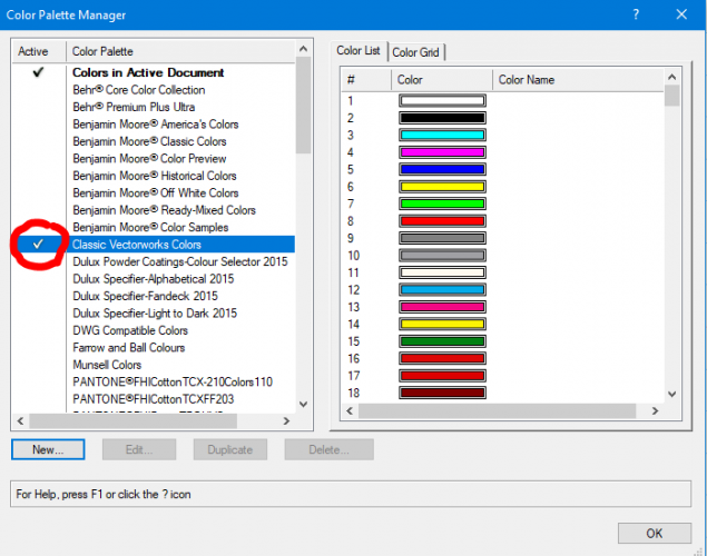
Now for the bad news; the colour palettes show up in the color palette manager, but sadly the custom colours don't display when selected.
If it's not showing up in the Attribute palette, did you checkmark your custom palette to make it active in the Palette Manager?
-
21 hours ago, grant_PD said:
Getting ready to migrate over to 2019...is there any documentation, other than the help file, that shows how the new titleblock manager is supposed to work? It looks very different to me...
Not sure what version your migrating from. If it's 2017 or prior, this webinar might help...
https://www.youtube.com/watch?reload=9&v=jFLNVWW0pyE
If it's 2018, I couldn't find anything that discuss changes from 2018 to 2019.
-
I like to spread out across two monitors. I feel too constrained on one monitor, although I'm still rocking 1080p's.
I'd really like it if palette docking worked on the second screen.
I'd also love to be able to lock my workspace once I have everything where I want it so I can't accidentally drag a palette out of position.
-
If they are saved palettes in the Color Palette Manager, you should be able to copy the xml files over from your user data folder...
C:\Users\USER\AppData\Roaming\Nemetschek\Vectorworks\2018\Libraries\Defaults\Color Palettes
to
C:\Users\USER\AppData\Roaming\Nemetschek\Vectorworks\2019\Libraries\Defaults\Color Palettes
Then open the Color Palette Manager in 2019 and checkmark them in the list to make them active
-
2
-
-
Well crap. Thought I explored everything in that Publish command, but somehow missed that Options button becomes active only after you move one or more sheets to the right hand side and highlight them. Thanks guys, appreciate the help!
-
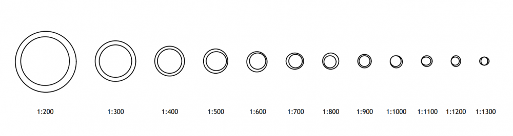
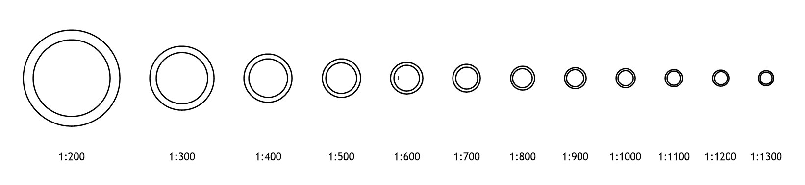
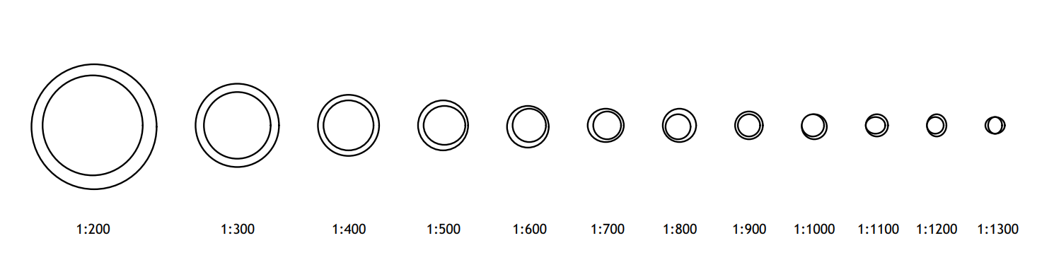
Thanks! The DPI setting on the Export PDF dialog does appear to help fix the issue. Although I have to set it about 1200 DPI before all the circles look correct which seems excessively high.
I guess the next question is how do I set the DPI with the Publish command? This is how I normally export PDFs since my drawings almost always have multiple pages. I can't find anywhere to set the DPI when using Publish, and it doesn't appear to use the DPI of the Sheet Layer.
-
Can someone explain what this weirdness is when exporting to PDF?
1. Draw two circles at x:0 y:0, one with 2'0" diameter, one 2'6" diameter on a design layer with scale of 1:24
2. Create a viewport to sheet layer
3. Duplicate a few times each with a different scale from 1:200 to 1:1300
Everything looks fine on the screen...

Export to PDF and things get funky. What's going on here?


Raked Hanging Position Truss
in Entertainment
Posted · Edited by LJ TMS
Hey that's awesome, I'll definitely let them know you said hi! How long ago did you work at TMS? I've been here going on 12 years, although I'm always working away in my cave so rarely get to talk to majority of the people that work here, lol.
Edit: Mario told me to let you know he misses you.