Scott Campbell
-
Posts
175 -
Joined
-
Last visited
5 Followers


-

Length of railing and fence as a property in IFC?
Scott Campbell replied to aage.langedrag's topic in General Discussion
@aage.langedrag I will pass along your comments about finding parameters and expectations for info in the OIP. You make good points. As for the rounding/reporting of the value, I’ll check further and see if I can find an explanation or a workaround. As you imply, I may have to buglist this too. -
Length of railing and fence as a property in IFC?
Scott Campbell replied to aage.langedrag's topic in General Discussion
Hi Åge -- It seems if one selects "Length(3d)" under "Specialized for Fence" in the Select Function dialog, we get a correct calculation. What I don't understand is why the value returned is 0.003. The Fence in your file is 2.685 meters long. The returned value seems to be that value rounded and divided by 1000. 0.003 is the Length value for the Railing too, which you say shows correctly. Can you shed some light?
-
Hi Stefan -- This sure sounds like something you ought to be able to achieve by scripting. Good opportunity for diving into Vectorscript, perhaps? Sorry to say, this is far from my strong suit, but there's a useful introduction to scripting in Vectorworks (both Vectorscript and Python) here: https://university.vectorworks.net/mod/scorm/player.php?a=348¤torg=articulate_rise&scoid=696
-
Site model contours - update 4
Scott Campbell replied to Ross Harris's question in Wishlist - Feature and Content Requests
In the Site Model Settings, deactivate "Custom lable placement" and put in 0 for "Maximum Labels per contour." OK. This will eliminate all automatically generated contour labels. Then go back and activate "Custom label placement." You'll now be able to use the "Add Contour Labels" button on the OI-palette to create your labels along a polyline wherever you want them. -
Thanks for the clarification. As far as I know, the "Truss Properties" dialog can only be accessed via an instance in model (right-click on truss instance and chose from context menu). So, that brings us back to start: Vectorworks crashes when attempting to place an instance of a Truss object in the model. I think we need to troubleshoot based on the crash, and now it seems necessary to ask you to share a file with the Truss culprit, if you can, for testing. Thanks.
-
Right click on the Truss symbol in the Resource Manager and select "Attach Record…". Highlight the Record you wish to edit, then click the "Edit values…" button. Be aware that the edited record values will not be updated in any truss instances previously created in the model.
-
OK @aage.langedrag, now I see what you are talking about. You actually do want the snapping, but you don't want the snapping to split the grade object that you are snapping to! So, I take it all back: this is not a bug, but a wish afterall. Thanks for the clarification!
-
After testing, I'm not able to replicate the issue you are describing, @aage.langedrag. (see video, below) Maybe you can share a file in which this issue occurs? Vectorworks 2024 Update 4 macOS 12.7.2 snap-gradeobj.mp4
-
This certainly sounds like a bug, Åge — you should never be able to snap to objects in classes or on layers which are invisible. I’ll run some tests to confirm what you’re experiencing, then we can argue about who’s going to buglist the problem. 😉
-
I've talked to @Katarina Ollikainen about this thread today. We hope to be able to get back to you all shortly. Sorry about the delay.
-
Remember @aage.langedrag and @Helene Bast to "up-vote" the Wish List items you want prioritized (like this one!) by clicking on the arrrowhead in the upper left of each Wish List window!

-
Åge - This is a rather detailed and specific challenge you’re presenting. I know there is work being done on the Plants, Plant Record, and reporting in Vectorworks. Let me coordinate with a couple colleagues, have a look at your files, and get back to you asap. You’re not in a hurry, are you? 😉
- 6 replies
-
- 1
-

-
- plant record
- worksheet functions
- (and 1 more)
-
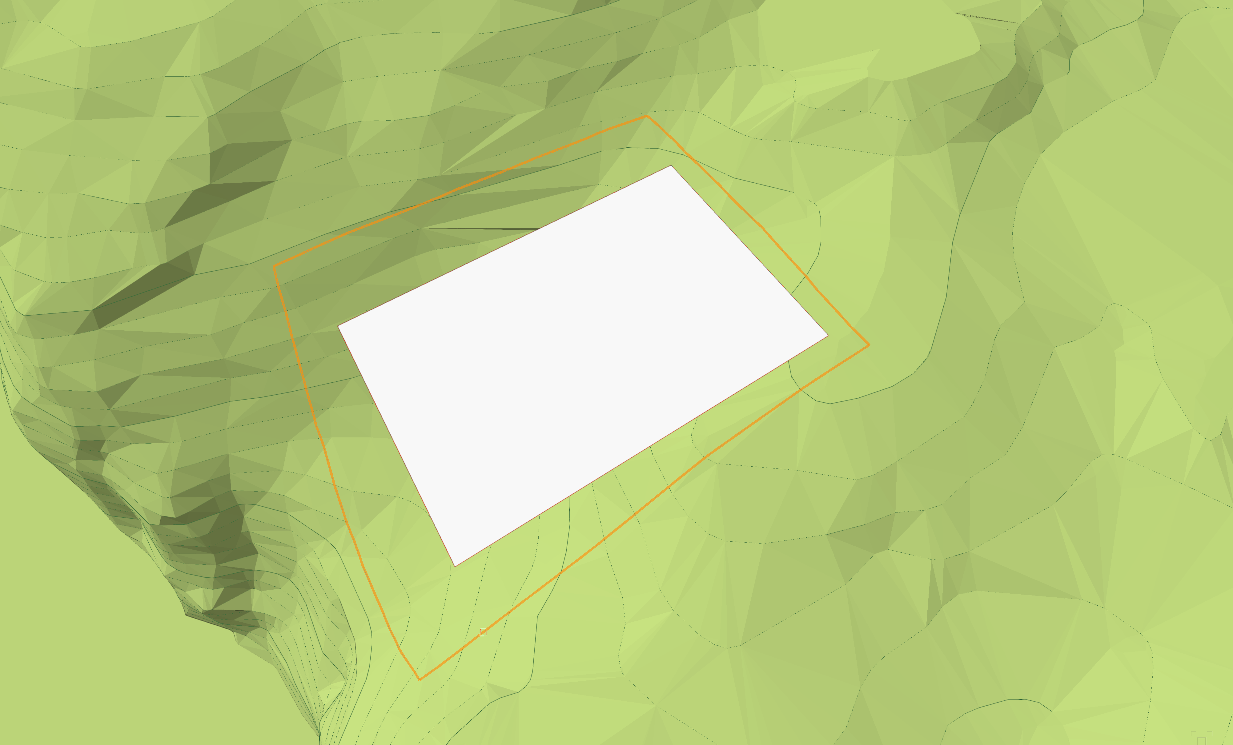
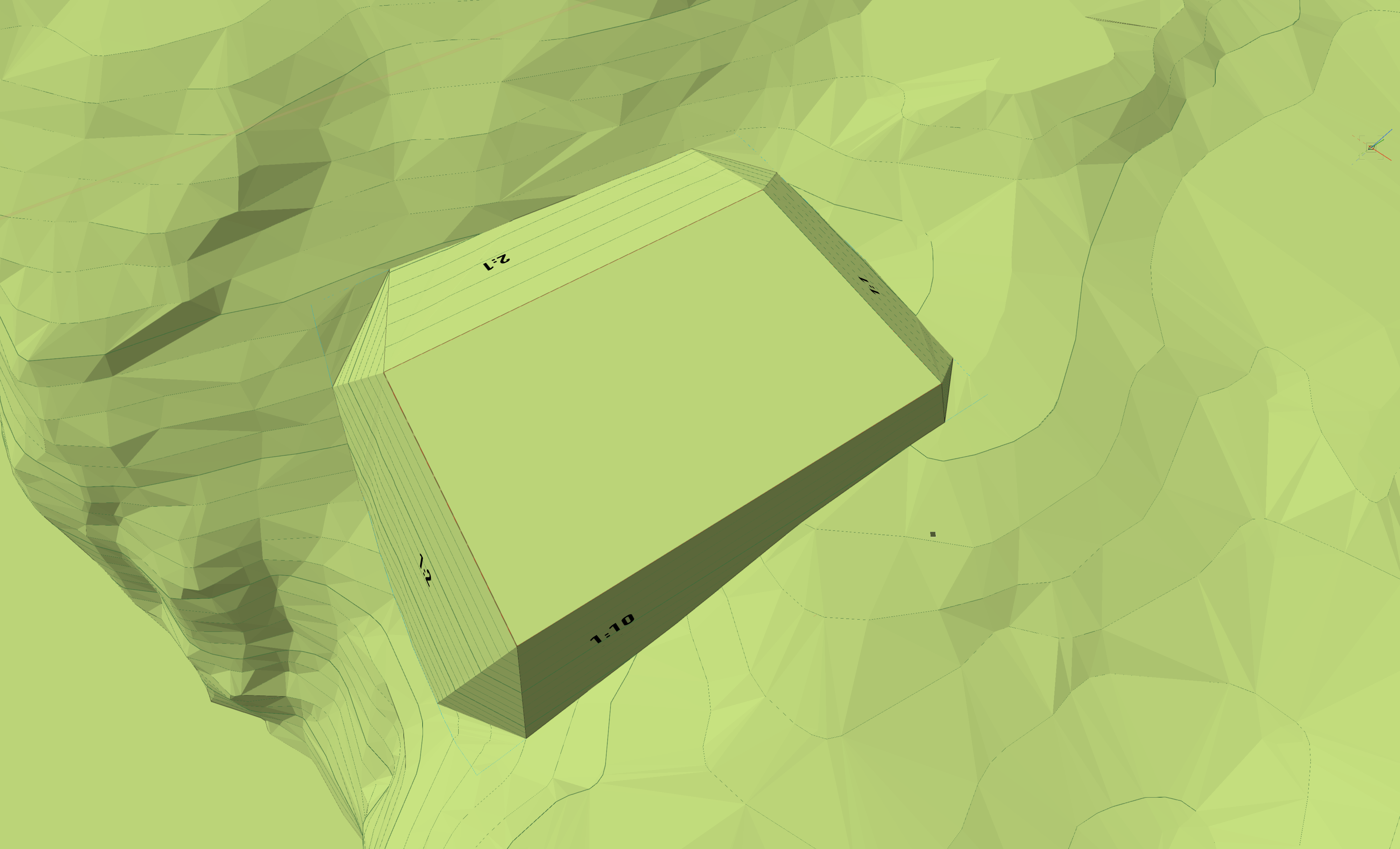
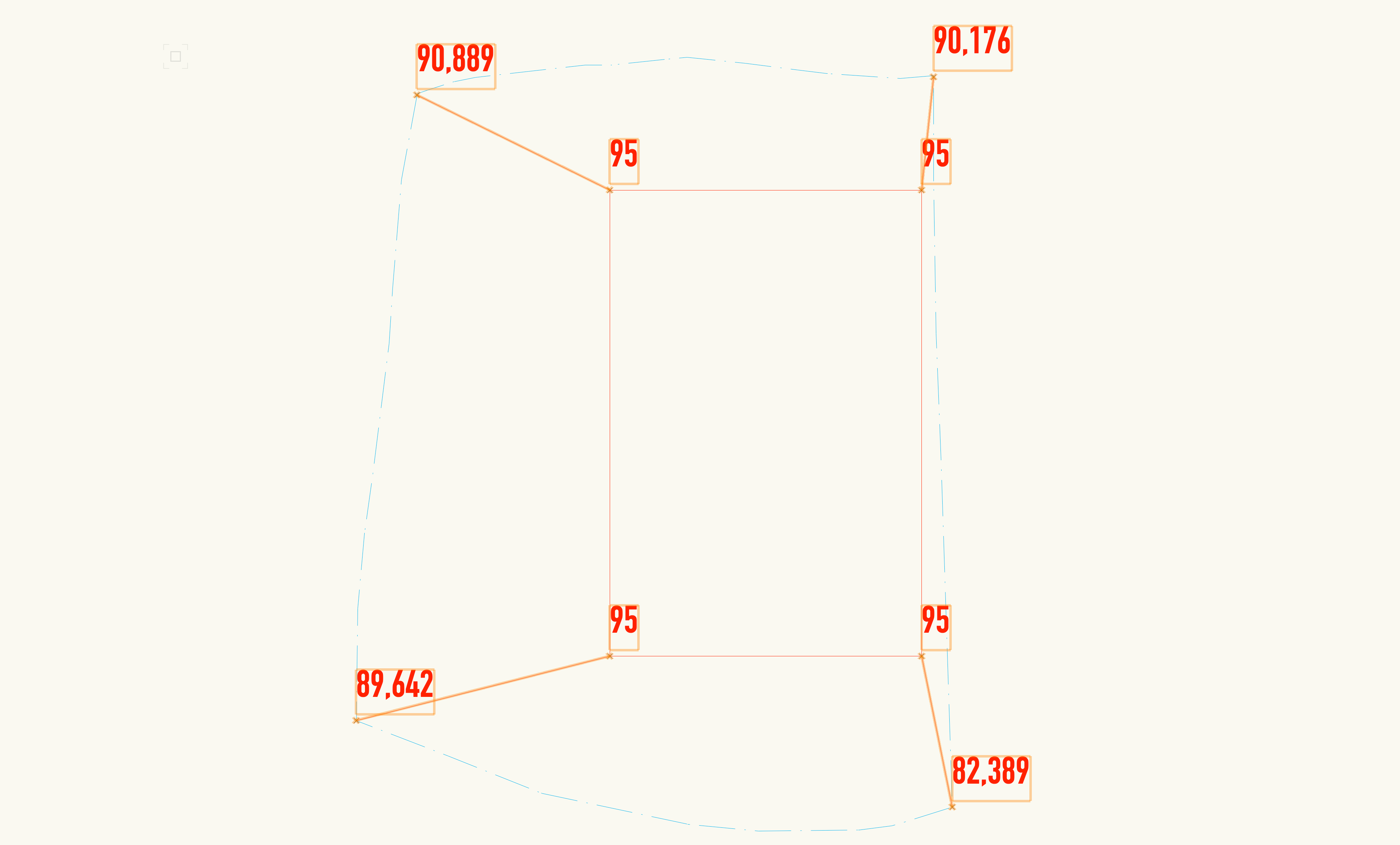
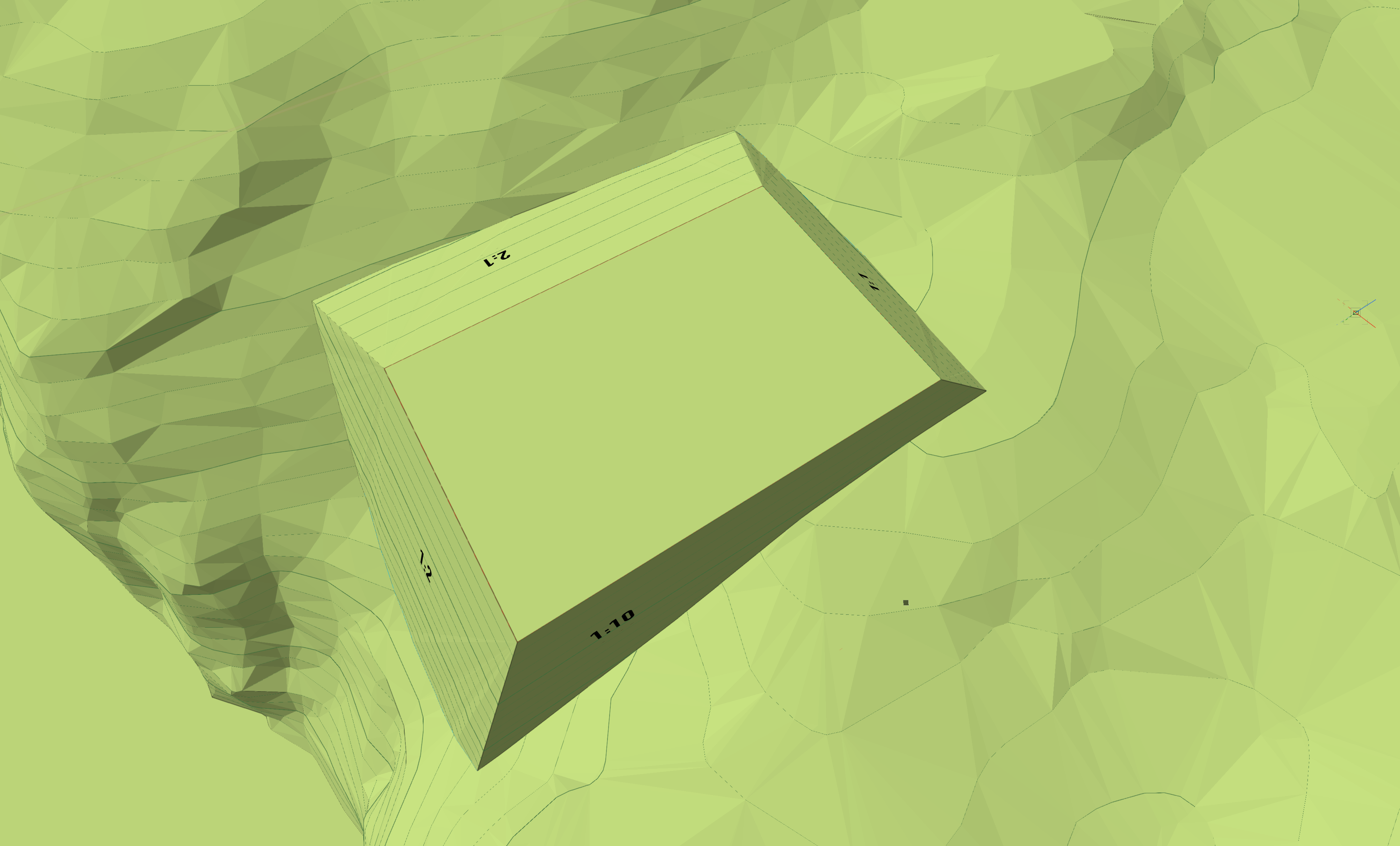
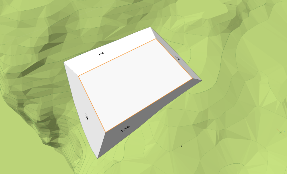
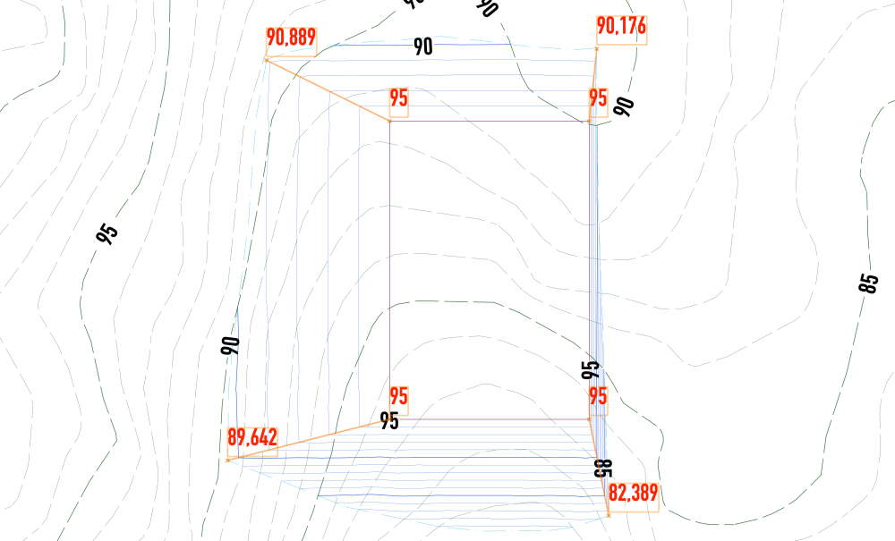
Hello @aage.langedrag and @Eric Gilbey, PLA I don’t believe “Create Grade Limits from Planar Pad” is going to get what you need, Åge (if nothing else, you're limited to the same slope in all directions and from all edges of the planar pad). As a matter of fact, I don’t think Vectorworks currently has the tools to do what you’re trying to do. It’s frustrating to be so near, and yet so far from a precise and simple tool to do what you are asking. The closest I can get uses basically methods that it looks like you have already tried out yourself. But I’ll sum up here what I find to be the best work-around I can find at the moment in Vectorworks 2024. It’s possible to accurately model a solid which gives you any battered slope you want from the edge of a planar pad. In this example I’ve used 4 different slopes on four sides of a rectangular pad. One sees clearly where each battered slope intersects with the site model. It would be lovely if we had a tool to automatically find this 3D shape that corresponds to the exact intersection between the solid and the site model surface. As far as I know, we don’t have this. Please correct me if I’m wrong, @Katarina Ollikainen, @Eric Gilbey, PLA, @Vlado or @Tony Kostreski. But it is possible to quickly draw a 2D polygon in Top view and convert it to a Grade Limits. It drapes itself on the site model surface. The battered slopes look pretty even and good, but Vectorworks doesn’t get the corners quite right — at least not without some helpful proding. Grade objects in each corner of the pad, can be snapped with the lower elevation at the Grade Limits object rather easily. This results in proposed contours which are more or less what we’re looking for, don’t you agree? I’m sorry that this is not the automatic, super-precise solution that it should be. But I hope you find it of some help, nevertheless. I will ask around to find out if there’s something you and I are missing here, and most importantly: Just how we can influence the process to build this sort of automated slope control into Vectorworks of the future.


-
LandXML Import/Export
Scott Campbell replied to kwik's question in Wishlist - Feature and Content Requests
This is a long-standing wish, here in the Nordics at least. Eh, @Jutta Telivuo @Basem @John S. Hansen @aage.langedrag @Daniel Ewald @Helene Bast? To up vote this wish list item, hit the arrow pointing up at the top left of this post. Thanks!- 1 reply
-
- 6
-