
Tamsin Slatter
-
Posts
1,890 -
Joined
-
Last visited
Content Type
Profiles
Forums
Events
Articles
Marionette
Store
Everything posted by Tamsin Slatter
-

Creating a viewport from design layers
Tamsin Slatter replied to Monique Freese's topic in Architecture
I like this method too - because you can see the other things on your sheet as you create the crop. -
Try the Site Modifier in Pathway mode. Here you can create any shape you like, with curves. The pathway has a longitudinal profile that can be modified to set precise elevations, You can also create as many transverse profiles as you like. The pathway starts out with a fixed width, but you can reshape as required, Once you’ve created your path modifier, add the hardscape and tell it to drape. Hope that helps.
-
a hardscape that mimics the existing site model surface
Tamsin Slatter replied to zhoukaiyi's topic in Site Design
No need to use Send to Surface. Just change the Site Modifer to Draped and it will fit the surface of the model. -
Site Model not Updating to Align with Hardscapes. VW 2024.
Tamsin Slatter replied to Jack2022's topic in Site Design
Apologies Jack - you always need to enclose modifiers with at least one grade limit. It's not a 1:1 relationship. It just sets the boundary for interpolation. The grade limit COULD be the whole site, or you could have several limits if you are making changes in several areas, but don't want to touch the land in between those areas. Maybe you want to protect the root zones of existing trees - areas outside a grade limit will not change. Areas inside the grade limit WILL change. -
Grade Site Modifiers Not Working as Expected
Tamsin Slatter replied to Jack2022's topic in Site Design
Yes, add a Grade Limit - it CAN be around the whole site, or it can be around a specific area that is allowed to be regraded. -
The great thing about the Public Roadmap is that it's a direct line to the engineers and product planners.
-
Thanks @Poot. I have let our product planner know about this requirement. It might be a good idea to also request this on our public roadmap: https://www.vectorworks.net/en-US/public-roadmap
-
Hi Helen It looks like your plant properties are set to "By Instance". If you change them to "By Style" does that improve things?
-
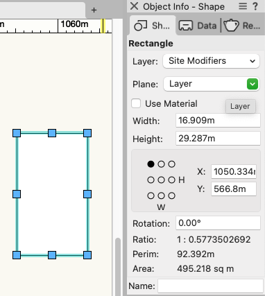
Not sure what the problem is. I've drawn a rectangle with the rectangle tool and here is the area, shown at the bottom of the Object Info palette:
-
Site Model not Updating to Align with Hardscapes. VW 2024.
Tamsin Slatter replied to Jack2022's topic in Site Design
The Grade Limit determines the area that can be updated by site modifiers. You don't have to put one around every site modifier. But you would enclose an area that is to be updated. They enable you to prevent having to regrade the entire site when you are just making changes in one area. Here's a rough example. I've got the Grade Limit selected so you can see it clearly. So, any of this area will be updated by the addition of site modifiers (pads, grades), but the contours outside this area will be unaffected: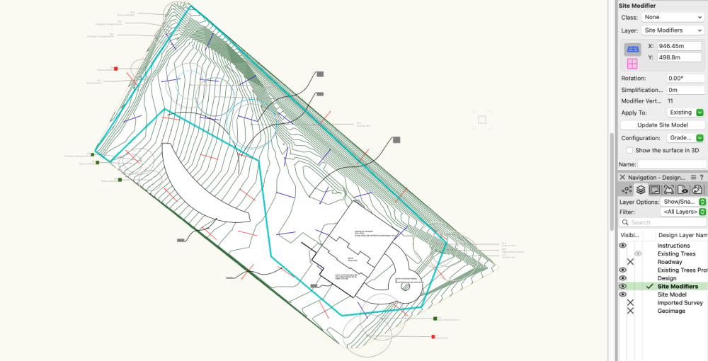
-
This might help. It's a few years old (like me), but don't let that put you off: https://university.vectorworks.net/mod/page/view.php?id=617
-
Apologies for the late reply. I'm not familiar with the datasets available to you in Denmark I'm afraid. In the UK I am able to get hold of free contour data from OS Openmap, but it involves downloading from the website and importing shapefiles. https://osdatahub.os.uk/downloads/open Although the shapefiles are 2D, I then use the Modify by Record command to Elevate the polys by their height value in the attached record. You can also use the same command on information that is linked through the Bind to Feature Service on a design layer.This will lose the connection to the original source data but that's no worse than downloading contours and importing them. I hope that helps.
-
I'm not sure... why you are not able to see it. See my note above about adding it to the workspace. The AI visualizer is processed on Vectorworks Cloud Services, and is available only with a subscription or as a benefit of an active Vectorworks Service Select agreement.
-
If you're up to date on the Cloud Services app, all is good with that and you won't see the Refresh button. Within Vectorworks, if you don't see it on the Model menu, you may be using a workspace that has saved itself in your user folder and is therefore considered a "custom" workspace. You can add the menu item yourself using Tools > Workspaces > Edit Current workspace. And you may also find it under the Windows > Palettes > Web palettes menu. Good luck!
-
Site Model not Updating to Align with Hardscapes. VW 2024.
Tamsin Slatter replied to Jack2022's topic in Site Design
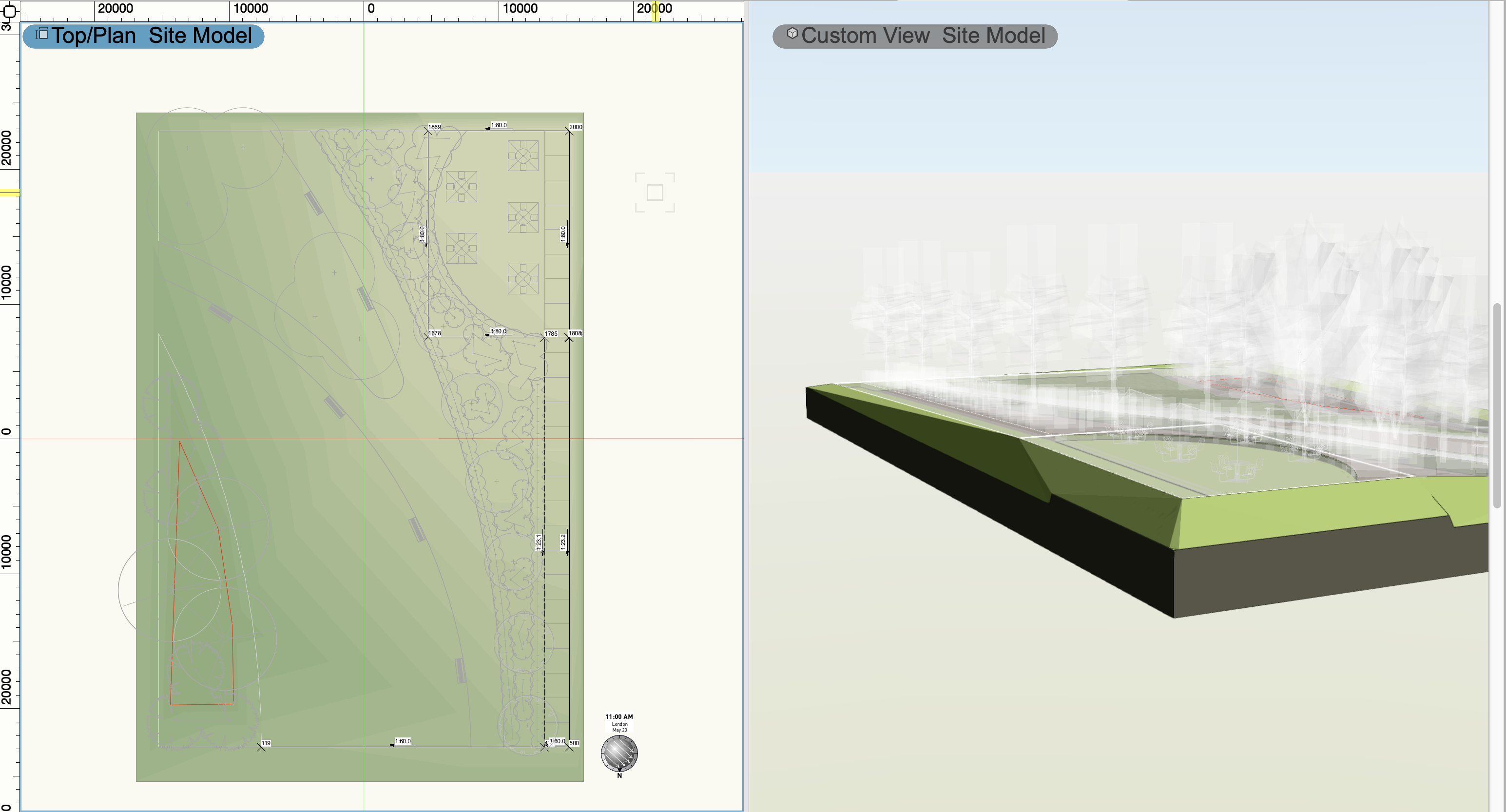
It should grade the area within if you create a completely closed set of grades. You need to make sure you choose the option to update the site model: And don't forget to enclose with a Grade Limit (mode from the Site Modifiers tool. Here's a screenshot of a small example file - on the Top/Plan view on the left you can see the connect grade objects that create the pathway up to a cafe area at the top right. On the 3D view, you can see the impact of those grades on the site, and you can also see where the draped hardscapes have excavated the site.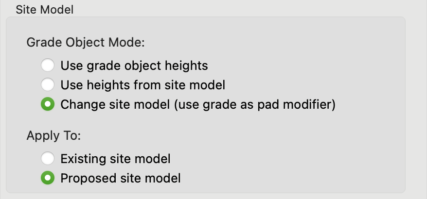

- 20 replies
-
- 2
-

-
- hardscape
- hardscapes
- (and 1 more)
-
Vectorworks 2024 Symbol with coordinates shown
Tamsin Slatter replied to TeeMuki's topic in Site Design
No - my apologies - an Auto Hybrid can contain only 3D geometry so won't accept a hybrid like a Stake or a 2D/3D symbol. I'm sorry. I wonder if you could create a symbol that includes a 3D Locus and then maybe use a Data Tag to report the information from the Locus? -
Vectorworks 2024 Symbol with coordinates shown
Tamsin Slatter replied to TeeMuki's topic in Site Design
In haste - with little time to check... I THINK you might be able to do this by creating an Autohybrid which contains the stake and a symbol. But can't test at the moment... Maybe you can and I'll look a little later! Good luck! -
Site Model not Updating to Align with Hardscapes. VW 2024.
Tamsin Slatter replied to Jack2022's topic in Site Design
I would suggest you try the Grade tool alongside your Stakes to control the surface of the site model and then look at Draped as the Site Modifier option in your Hardscapes. Then they will align to the (graded) surface of the site AND cut the site model. It’s magic. Using Aligned means that the hardscapes are looking for specific object types to align with. Draped will align with the site model. Also, if you have problems with getting the site model to respond to different layers, look in the Site Model settings and see which layers are set to modify the model. I hope that helps.- 20 replies
-
- 1
-
-
- hardscape
- hardscapes
- (and 1 more)
-
You'll also need to update your Vectorworks Cloud Services app. Just open it, go to the About menu and run Refresh. Then restart Vectorworks.
-
Yes - it's great. Many more new toys in Update 4! Have you played with the AI Visualizer? Warning... it will immediately prevent you from doing anything useful for hours!
-
Also, update to Update 4 and the Selection tool now has this mode:
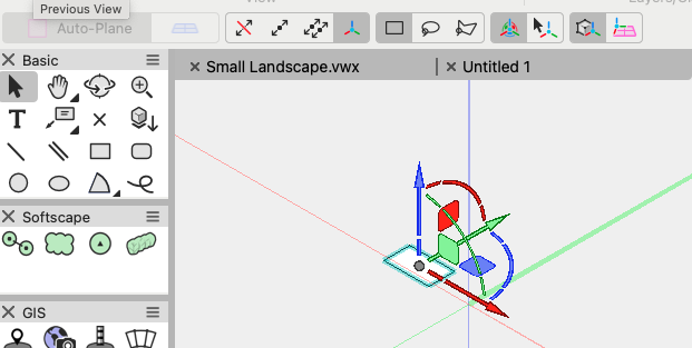
-
Setting a Georeferenced Template Back to 0/0
Tamsin Slatter replied to lrucker's question in Troubleshooting
Liberty, if your Vectorworks file is correctly georeferenced with the same local coordinate system that the DWG is generated from, then all you need to do is: 1. File > Import > Import Single DXF/DWG. 2. On the Import dialog, check the box for This file contains georeferenced geometry. Your data will land in the correct place. If you watch the webinar that Peter linked above, I think that will help you. If you would like to post a sample file, I can make sure… -
Setting a Georeferenced Template Back to 0/0
Tamsin Slatter replied to lrucker's question in Troubleshooting
Thanks for the plug @Peter Neufeld. Just to add, if you really, really want to turn OFF the georeferencing, you can do so in the File > Document Settings > Georeferencing command. The dialog offers two things that are set. The first is the local coordinate system that is to be used - that will stay on no matter what. In the screenshot below, I used a blank UK template. By default that is set to EPSG 27700, which is the most commonly used coordinate system in the UK. 0,0 is off the South West coast. The second is on the right side of the dialog and relates to the coordinates that you want the internal origin to represent within that coordinate system. So, by default, in a UK file, the internal origin starts life in Greenwich in London (for no good reason other than we had to put it somewhere and thought this was recognisable). But as you can see in the screenshot, I have used the checkbox to disable changing the location and orientation of the internal origin. Now, it's at 0,0 of the EPSG coordinate system. Not the Long and Lat that you can see greyed out in the image. I can still use the Geoimage tool but it's clearly showing the internal origin out in the sea, at 0,0 (OK, not THAT clearly, so I drew over it - please forgive a little artistic license!)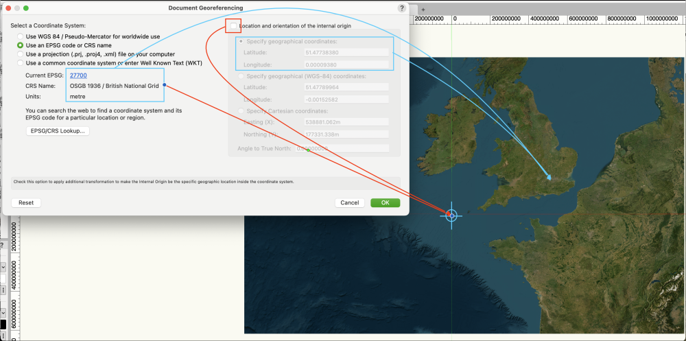
-
Sending to Site Surface - Confirmation
Tamsin Slatter replied to Michael Siggers's topic in General Discussion
Is it the building that you are trying to send to the surface? If so, I would probably instead put the building on its own design layer and change the elevation of that layer to the desired level. -
Sending to Site Surface - Confirmation
Tamsin Slatter replied to Michael Siggers's topic in General Discussion
To have them align correctly, the building file would also need to be georeferenced. The reference will land at its coordinates from the original file, so if that isn't in the correct place, it will need to be moved. You can use the coordinates on the Object Info palette to move it precisely. But I would probably prefer the option of georeferencing the building file so that both files are using the same coordinate system.