

MattG
-
Posts
655 -
Joined
-
Last visited
Content Type
Profiles
Forums
Events
Articles
Marionette
Store
Everything posted by MattG
-
Hey Benson, That worked great as well. That seemed like a little bit more streamlined way to do it, but each way works well. Thanks, Matt
-
Hey Kevin, That worked well. Thanks for the help. I wish there was a way to extrude the polyline I drew and just choose it as a slice plane. It just seems like a few too many steps to achieve this. Matt
-
I am attempting to do a slice on a 3d object. I do this semi regularly, but I am curious if someone has a better thought on how to do this. I have for arguments sake a cube. I go to the front view of the cube and I am basically needing to split it in half, however I need to split it in half with some detail along the line I want to split. The line I want to split on has sort of teeth on it. I want to split to go all the way through my cube, but to follow that path of the teeth. I cannot really figure out how to achieve this. I am attaching a little image of what I am trying to do. I want the redline to basically extrude through the 3D shape and have two separate pieces. One with the teeth on top and one with holes for the teeth on the bottom. Thoughts?
-
Thank you very much, that was very helpful as I never thought about applying a hatch to a extracted surface. That creates the look I was attempting to get in a perspective view. However I am curious if there is any way of doing this to actually make 3D geometry without detailing out all the 3D geometry by hand. I don't really need this, but it is a thought I had. Say I wanted to create a section where I just made a 2D polygon from a extracted surface and I put a hatch to represent siding on it. In my section I would not see any representation of the actual siding because the siding is essentially flat. I am thinking this isn't really doable without going through and modeling everything, but worth asking. Thanks again. Matt
-
I have to preface this with the idea that I am primarily working in the lighting industry with little experience using the architectural tools. I am attempting to do a 3d perspective view of a corner of my house for a contractor. I took some measurements of the area drew some walls using the wall tool and it seems okay. What I am hoping to do is to get the view to more accurately represent what is there. My final output is either a hidden line or final shaded polygon rendering on a viewport. This portion of the house has a poured foundation that goes about 1' ish above grade. Following that it has siding for most of the way up. I am trying to get that to show up in a hidden line view. How can I get a rendering texture on a wall that will make the look of the siding appear in 3D on a hidden line view? Also if I can do this how would I do this in a way where I have it start at a 1' elevation? Thanks, Matt
-
I think that is the problem unfortunately. Because it looks so similar to excel but doesn't act the same as excel it can lead to large amounts of frustration. I am of the believe that if it is going to resemble something we already know that much it should act very similar to it. I miss the fill handle to do the operations like you mentioned where you can just pull down and have a function repeat for the new cell. I appreciate the ideas for workarounds, just annoying that they are not actually able to perform actions in a similar manner.
-
Very cool thanks. That was what I was looking to do. It is still a little counter intuitive compared to working in Excel, but at least it can perform that function. Thanks as usual for the worksheet help. :0)
-
This is a constant point of frustration for myself as well... Unfortunately I do not know of anything beyond what Kevin mentioned. I would be interested in hearing if anyone else has some magic secrets to help solve this. Matt
-
I am curious to know if I just have not located this or not, but I am hoping to be able to sum in a worksheet. Right now I have 7 rows of data. This is manually entered data in a spreadsheet form not data from a database. I am debating if I want to use this little template worksheet I've made on my future drawings but I am noticing a problem, the sum function in Vectorworks. Right now if I understand correctly I can put in my eighth row a "=SUM(A1,A2,A3,A4,A5,A6,A7)" and I subsequently get the sum of these items. Now I am comparing this to Excel and I can just put "=SUM(A1:A7)" and get the same result. For what I envision using my worksheet for I am going to potentially see very large row counts and manually entering every cell in this manner would prove very tedious. Is there something I am missing to do this or is this "working as designed" and just not able to do what I want.
-
I have a worksheet that I tried to add a image too. I had a database row referencing lighting devices. When I added a column and inserted a image function I did get the image for the lighting device. What I do not want is for it to show a specific lighting device as there are label legends applied to the images for the lighting devices. Does anyone have any idea how to insert a image without the label legend and only get the symbol view rather than a lighting device view? Thanks, Matt
-
I get a vectorscript error when I change a title block on a drawing boarder on a sheet layer. Any time I do this I get a error that reads "Warning:_4821_4835-Object Handle is not to a 3D object." Does anyone know what this means or how to get this to not longer appear. It does not appear to actually do anything, but it is just really annoying and I cannot locate anything in the help on it. Matt
-
Perfect, thanks.
-
I am trying to figure out a way to take all my lighting device parameters that have their types set to text and have them act as numbers. I am specifically attempting to do this for the weight parameter. I have a truck pack file that I want to be able to drop a grouping of fixtures in and actually account for that weight in my report. However with it currently viewing weight as a text parameter I am not able to do this. Does anyone have any thoughts on how to do this? Matt
-
I am in the market for a new large format plotter. I am currently using a HP Designjet 1055CM Plus plotter. It has been acting up and I believe it is time to be replaced. I am leaning toward a HP DesignJet T520 ePrinter and I am interested to know if anyone has any experience with this plotter. I am also considering either a Canon iPF750 or iPF 760. I am ideally looking for a 36" roll with a decent memory to avoid processing delays. Speed is nice, but not the main determining factor. I found a few things online comparing some HP models to Canon models which brought up the comparison of consumables. Mainly that the ink usage on HP's are typically higher and the cartridges are also significantly smaller compared to the Canon's. I have only used HP plotters in the past so I might be swayed to stay with them, but I am interested in hearing other's thoughts.
-
Has anyone ever needed to pull a single layer out of a drawing and/or found a good way to do it? I am working on a project with a coworker in a new venue. I have made a new file where I imported the 2D dwg of the venue into it. I than saved this file and made a new file with my standard template file and referenced the venue drawing into my standard file. In my standard file I have basically traced all the important items in my world onto their own new layer in the file. I converted a lot of areas to 3D as necessary and made it the way I like. Also since that I have added a lot of other information. Now I basically want to only export one layer into its own file. I know I could potentially get around this by saving the file with a new name and deleting everything I do not want in this file, but I was hoping or thinking a useful export might be a layer export. Has anyone ever found a good way of doing this?
-
I understand the parts database and do not care for that. We do a lot of custom/unique things. It is often easier to just use the 3D symbol and rotate them opposed to editing all my symbols to meet the necessary criteria in the parts database. Also when you do something where trusses are at odd angles I will often build them in plan view and rotate in the appropriate view. This would be a pain to constantly adjust fixtures individually.
-
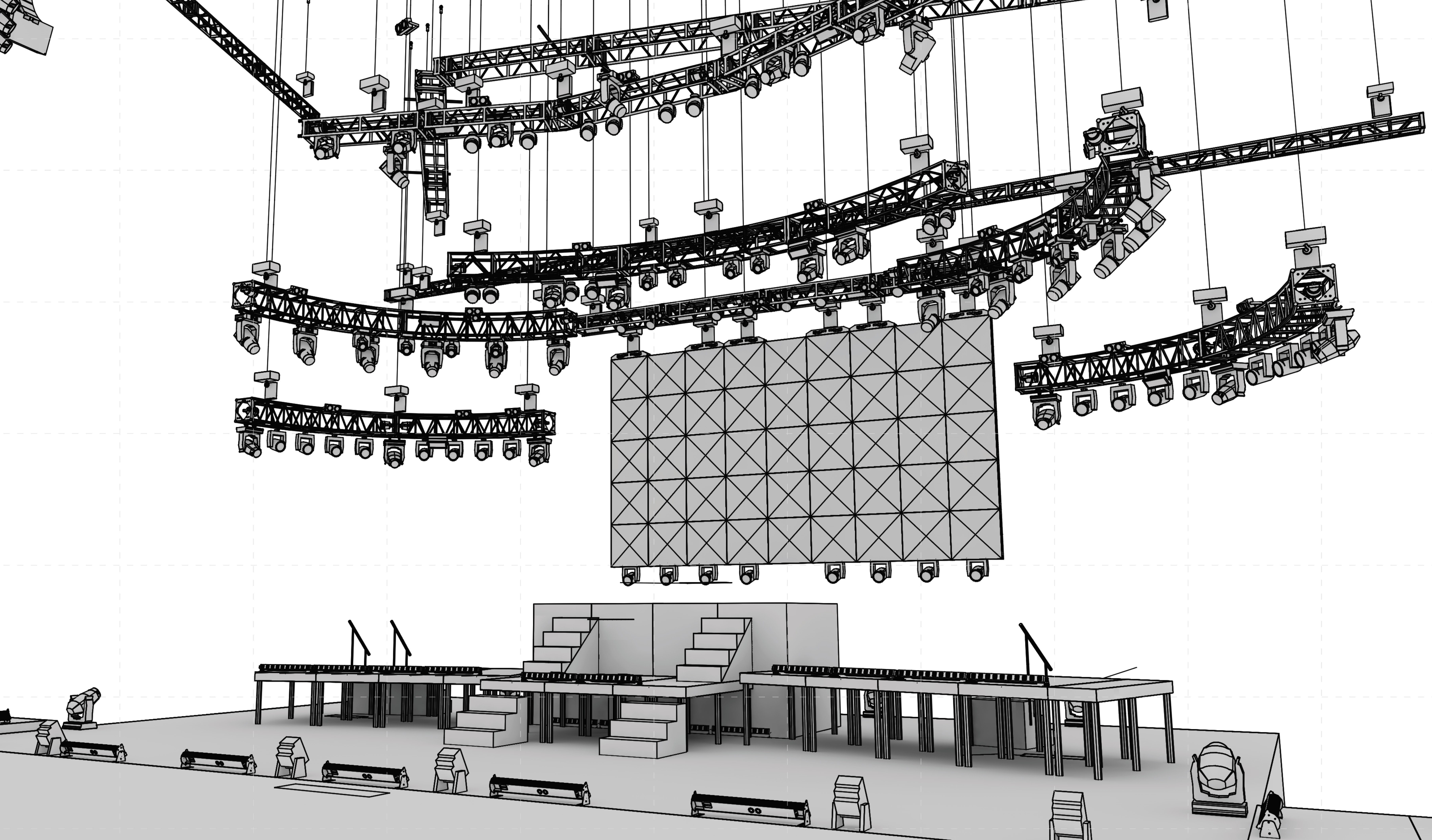
Has anyone come up with a solution for applying a label legend to a 3D only lighting device? I am working on a project with a number of curves that from a front view are making a frown. I am showing the lights in 3d and curving with the truss. I am using a 3D only symbol. However as soon as I apply a legend vectorworks wants to think it is a hybrid symbol and I can see my containers, but not the 3D symbol. I want to see the containers and the 3D symbol. I'm not sure if anyone has a option or thought for this. I have had similar situations in the past and I wound up making dummy lighting devices and just leaving the 3D symbols as symbols and not devices and applying the actual information to a dummy symbol that may of only been a 2D loci. However this gets really old really fast. Matt
-
That did exactly what I was looking for. Thank you very much. Matt
-
I am trying to figure out the best way to round a value in a worksheet. I have a worksheet I have generated that creates a list of symbols with a given record and displays the fields I want in the order I want. I have two columns one labeled "=(xcoordinate)" and "=(ycoordinate)". I typically like to have my units set to Feet and Inches with a precision of 1/8" or 1/16" of a inch. Now the exception is in this report I like to have it round to the nearest inch. I do not want fractional values in the document. My initial thought was to change my database header to "=round(xcoordinate)" & "=round(ycoordinate)". However this is rounding to the nearest foot. My question after all of this is what do I need to put in my equation to have my values appear as rounded to the nearest inch without changing my units to have a precision lacking fractions. Thanks, Matt
-
I am hoping someone has a way to do this without reproducing the geometry. My reason being I have done the above and similar operations, but we have had to modify our 3d elements for items and recreate the 2D portion as described. This just gets a little old and I wasn't sure if someone had some great secret way to do this that I did not know about. Thanks Matt
-
I am trying to get a hatch to appear when doing a 3D hidden line view of something. I have a hatch that is basically a wood grain hatch that I want shown on a isometric viewport on a sheet layer. However I am not sure how to potentially accomplish this without tracing everything on a layer plane at a isometric view and applying the hatch to that. I am pretty sure someone here has probably done this before and I am hoping they would be able to enlighten me on how to do this. Thanks, Matt
-
This is probably a simple one. I am trying to adjust my report I made to have it only count symbols with a certain record value present that are on a given class. I went and created the report to count all symbols with the given record. Now I just need to know how to write the criteria to include only a certain class. Anyone have the answer? Thanks, Matt
-

Copying viewport layers and classes to other viewports
MattG replied to MattG's topic in General Discussion
Never mind solved my own question. I used the eyedropper tool to achieve what I wanted. Matt -
I have a number of view ports set up that I like with the proper classes and layers on them. I created a new view port of a separate view but that view did not have all the layers and classes I wanted on as well as the various layer overrides and visabilites. Is there a way to select a viewport and apply a different viewports layer and class properties to it and possibly the render style, scale, etc... Thanks, Matt
-
I have had this problem in my work, and I have not found a real solution. A lot of my text in symbols is actually linked to record formats for the symbols.