
MattG
-
Posts
655 -
Joined
-
Last visited
Content Type
Profiles
Forums
Events
Articles
Marionette
Store
Everything posted by MattG
-
I don't use the LED screen tool too often. Using it on something and running into a mini issue, not sure if this is something someone else has a workaround for or not. I have a video panel that is a 1m & 1/2m sizes. The wall I am working with I used the module size and entered it as 1m x 1m. I am 5.5m tall. I then go to vertical count and enter 5.5, but it rounds to 6. Is there any way to have it show as 5.5 all as part of one screen? The reason I don't usually use the LED screen is I usually use symbols. I thought giving it a try to see pixel counts and things like that would be helpful. However, if I cannot make a wall of different parts it seems like that might be a missing key feature to the functionality of it. Thanks, Matt
-
If you shoot me an email mgohring@upstaging.com I'll send you their files.
-
I have a nice 4k Monitor I use as my main monitor. I know windows is goofy with scaling, but curious how or if Vectorworks is working to work well with it. I dock my OIP an Nav pallets on the right side of my workspace. I have the resource manager currently floating in my workspace on my main 4k monitor. I want to be able to drop it on the monitor to my right. It is 1920x1080. Anytime I do this it gets really strange in that it gets lost and shrinks and I can never find it again. Does anyone have any workaround for a way to do this or some thought on what a solution might be?
-

Hidden Line Rendering 20 min vs 3 Seconds
MattG replied to digitalcarbon's topic in General Discussion
That is my most helpful criticism with VW. I would love if more focus was placed on existing feature performance rather than coming up with new features. Yes new features can be nice, but honestly I have very little need or use for marionette or some other new revolutionary things. I would though love overall performance upgrades. I love when companies can just be straightforward and honest with their customers as well. I think that transparency is helpful and gives customers a bit more optimism about the products they are committing to. -
I am not super worried about my workflow. What I do is a lot different than architectural stuff. We get constant drawing changes for events and I find that I generally do not go with revisions or issues because things change so frequently. What I generally go with is anytime we open a file and start making changes I change the suffix on the file name to the current date. So "Client - Project Name - Year - Current Date (yyyy-mm-dd)" if that makes sense. So with what you mention yes the dates on there would be new, but we are also working on a file where the last used date is in there. For my purposes, I know, and this happens constantly, where a guy may come on site with a drawing that was printed a month ago which is a dozen revisions ago. I don't necessarily have to know to change the revision I can just look at the "date" on the drawing to know when it was generated. Open to other thoughts, but for me, that seems to make the most sense.
-
In the new 2018 title block where you can do the various dropdowns is there one that will just always put in the current date at open/save/publish or something to that effect? I am hoping to have one that will just always be filled in with the current date that the item is created. Since my primary output is pdf either via export or publish I am thinking if there was a field that auto regenerated at publish that would be ideal, but it looks like most are just empty field containers. Thanks, Matt
-
Cool thanks. Yeah this seems odd. Not necessarily catastrophic or anything, but I suspect something internally is not correct. I'm unsure if this would relate to Windows or VW either......
-
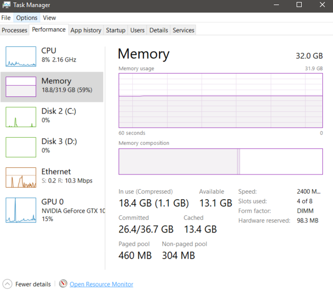
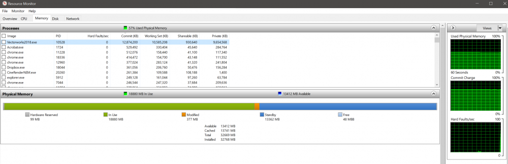
Curious more than anything here. I have 32GB of ram installed on the machine I'm using. I am using roughly 58% of my physical memory. I have VW running, I have outlook, chrome, acrobat, nothing else that is a crazy resource sucker. However, the VW file I am working in is very beefy. I am trying to be sure I am maximizing my machines performance ability for working in this. I feel as though more memory allocation to VW would be helpful, but I am finding that my memory is flatlining at 58% usage and at basically 12.8GB allocated to VW. Is there something between VW and Windows that caps the amount of memory that can be allocated to VW? I am actually wanting VW to be able to use more ram as weird as that might sound. Thanks, Matt

-
I am working on a project where we are dropping in 4-6 static cameras to run to a switcher. I have most everything drawn in 3D and thought if I can drop in some VW Cameras where I want the camera position to be I can make a hand full of viewports showing approximate views of each camera. I think that would be helpful to show to the people working on this project. However I am not super savvy in the camera world and I don't know that my camera cut sheet and the fields for the VW camera seem to match up and I am hoping for some help from someone on what I would want to enter in the different fields. Here is a link to a camera cut sheet on the lens we are using http://www.markertek.com/Attachments/Specifications/Marshall/VS-M246-2-Specifications.pdf In the Renderworks camera OIP I get the following Aspect ratio: I selected 2.4, That seems much wider then I would want I am guessing I really want 16:9? I was not sure if on the camera cut sheet that is the first number on the focal length? For Film size: I put in 16mm in my drawing that makes the focal length 10mm. It looks like the camera's is actually about 6mm? Not sure how to make this match Any other thoughts on what I can do to set up the camera in VW to match the file above as best as possible so I can just drop in those cameras to get the viewports I want? Thanks, Matt
-
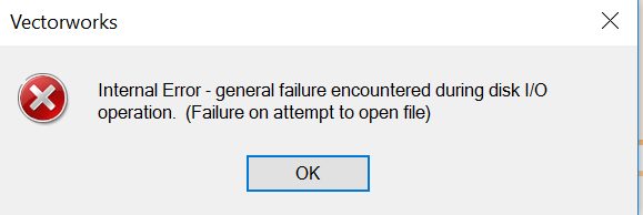
I am getting the following error, screen shot attached. Internal Error - general failure encountered during disk I/O operation. (Failure on attempt to open file) So I have searched for this error and it sounds like a few things. 1) a server issue. The machine I am getting it on isn't really using a server. It is on my home machine. I have a little 5 bay NAS at home but nothing that should be pulling from that. 2) a backup issue. This is one of my best guesses. My guess is because I have my user folder saved in Dropbox with the user preferences set to save backups to a custom location on my main machine at the office I get this because it is looking to backup to that location that does not exist on this machine. What are others thoughts? I will try to test this but my issue is that setting is saved in my user folder which I want in my Dropbox for a number or reasons. My only other thought is to put my VW Backup folder in my Dropbox, but right now I have multiple drives in each machine. I keep lots of backups of lots of files in a big spinning drive on each machine to avoid wasting space. 3) A second hard drive issue - maybe because my backup folder is currently on my "D:" drive on this machine and the location may be on a different drive letter at home that could be a culprit? Not sure though, this seems less likely. Anyone have any input or thoughts? Maybe a alternate workflow? Matt
-
No I get what you are saying. I know/understand how to do that. What I actually want to do is be able to extract the shape from the 3D geometry already existing. What you are showing is easy enough and get how to do. The reason I want to do it this way is more to find a better workflow in case they want to adjust the shape again I don't have to redraw, my how it just to extract or project? Any thoughts with that method? Matt
-
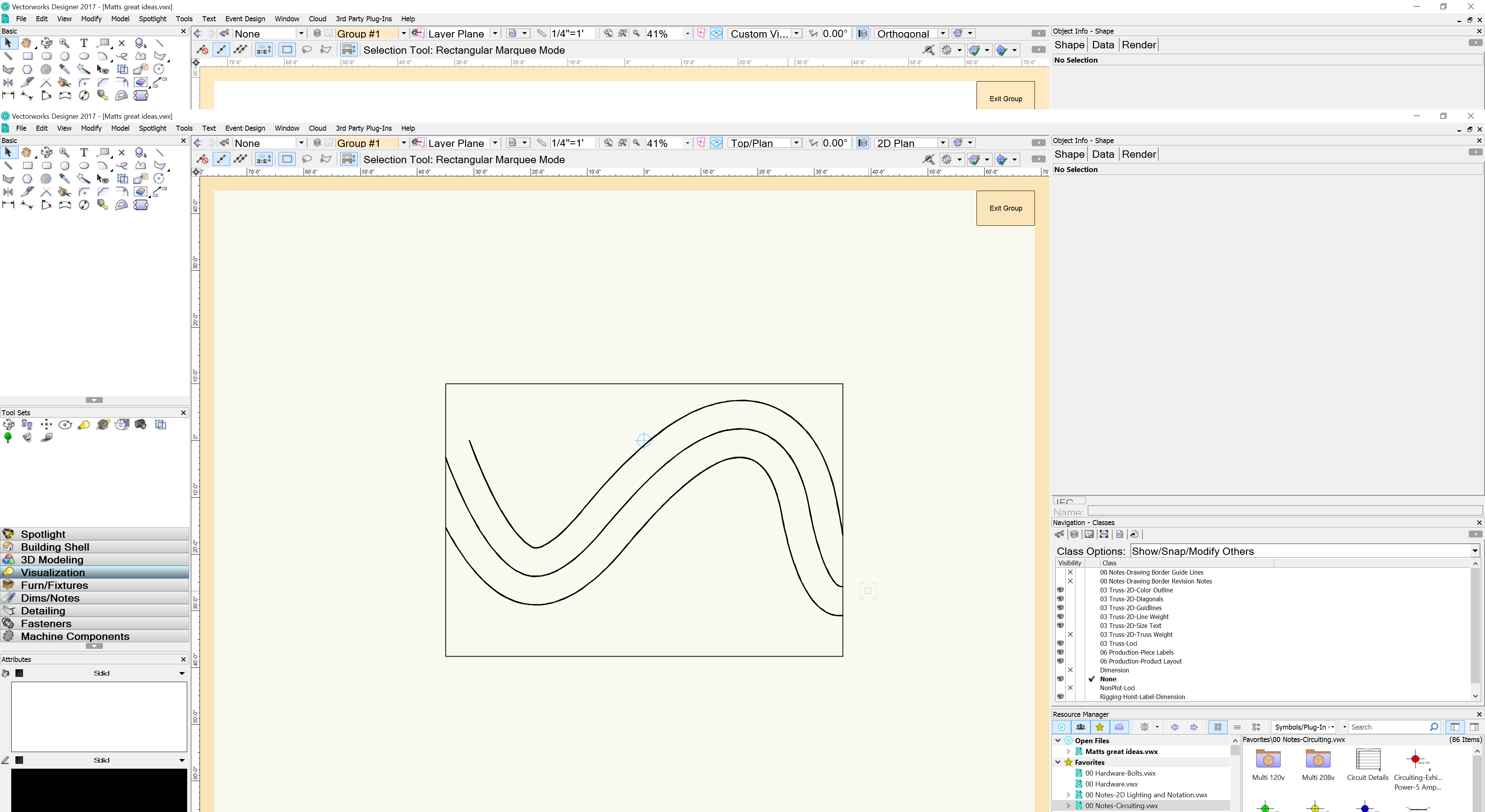
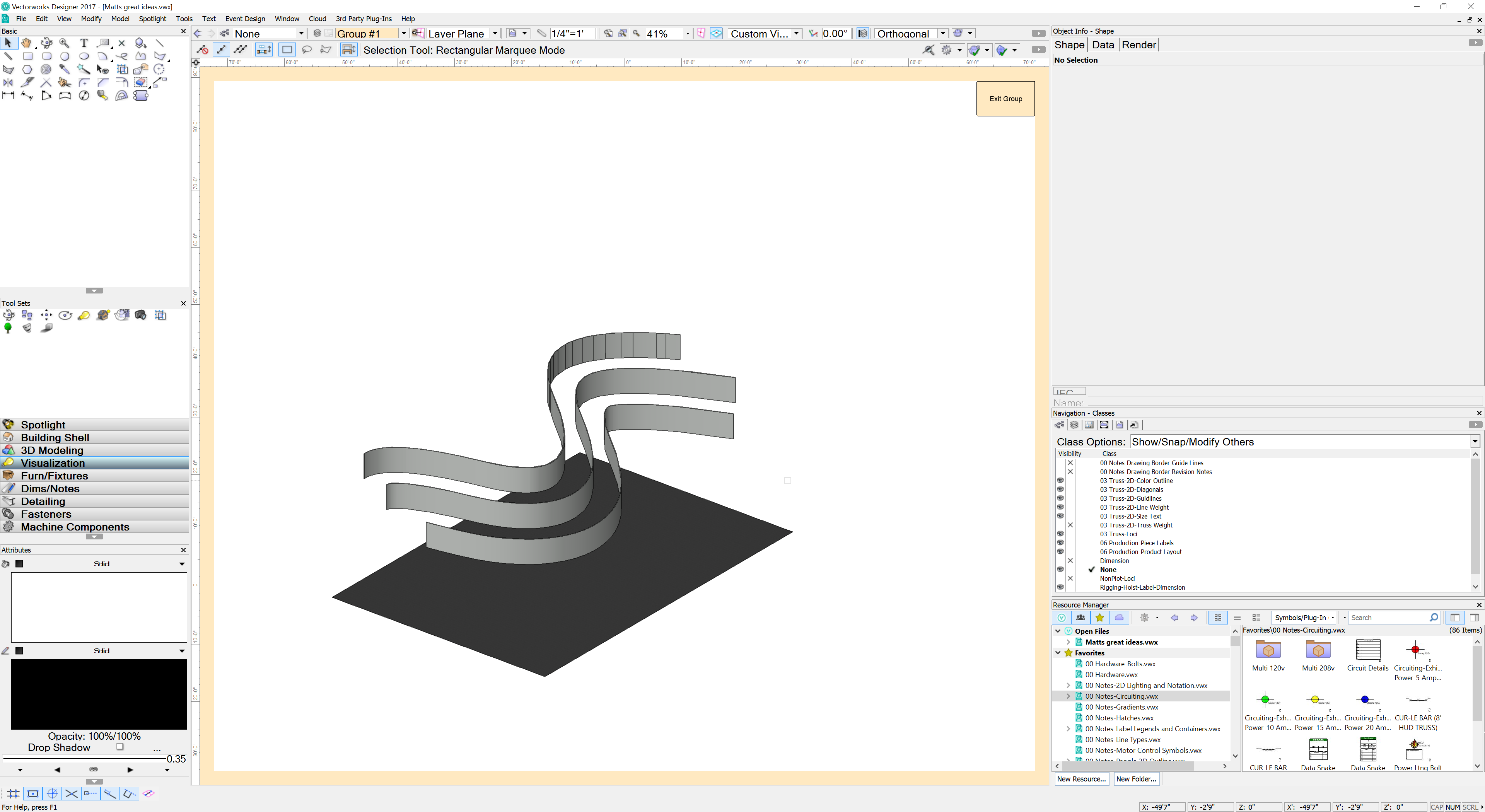
I know this is probably pretty easy, just went through a few tools and couldn't get it working for me the way I was envisioning. Basically I am attempting to create a curved header for a exhibit booth. I drew a bunch of options to show the clients for different curve options. Well the one here is the one they liked the best so far. Now what they are wanting is a path in the carpet to match. What I was trying to do was just project the two outside most curves straight down onto the 3D poly black floor and then extract that surface, but it wasn't working for me. Ideally I want a polygon of the curved surface on the ground plane that I can make into either a 3D poly or thin extrude. Anyone have any good ideas on the best way to do this? Honestly I may just edit the extrudes and pull out the 2D geometry, but I know there is a better way to pull this from the 3D but not sure. Thanks, Matt

-
I have been using VW for years and mostly have developed our own symbol library we use here. In that we have started making symbols with less devices type options that were available in versions many years ago. That said I have some people working here that I am finding it necessary to document what I have always just thought of as givens in my head. With that said I am making a little document spelling out how I want other people here to build symbols and just general VW workflow for how we create our documents. This has been on my list for a long time and finally getting a little time to look at it. With all that in mind I ran into a thing that I have come across in the past and sort of dismissed, but I am wanting to see what other peoples thoughts are. When you are making a new symbol and assigning a "Device Type" what do you assign to certain things. For me it is more or less as follows Light: Conventional light most likely one that connects to a dimmer, or possibly a single channel DMX Fixture that the DMX only controls intensity. We have LED Lekos, Fresnels, Pars etc that work that way, but they are only one control channel. This would be a very basic light. Moving Light: Anything that pans, tilts, changes color etc. Very easy with say a Robe BMFL, Mac Viper whatever. What I am having a difficult time with is where LED color changing lights fall into this mix. Not something like a Mac Aura that is definitely a moving light, but say a ColorForce 48, LED Par, LED Color Changing Mole Light? That is what is stumping me a bit. Accessory: Color Scroller, beam bender, gobo rotator, things similar to that that would get DMX but don't have a light source. Something you call up from a desk to help an already existing fixture. Static Accessory: Barn doors, top hats, iris, etc Device: Not entirely sure here, maybe something like a MA 4 Port Node, Networks Switch? Not too sure what others think would fall into this category. Practical: Lamp on stage, hanging chandelier, desk lamp etc things that are on and off built into a set piece etc. SFX: Strobes (Xeon, LED), Hazers, Foggers, Low Smoke, Lasers and similar Power: Not sure what this is intended for. Maybe just a symbol that is marked as a power drop? Maybe something that just needs power and nothing else? Maybe a small portable dimmer pack power that goes to it? I am not too sure here. Other: I guess this would be the catch all for anything else that does not fall into something above? I guess for me my big question is where would most people categorize multi channel LED. Things like strip lights, LED Pars, all the gimmicky LED stuff that is coming out. In my mind it is a moving light even though it does not move, but are others calling those devices or maybe even SFX? Just curious more than anything. If anyone wants to chime in I am curious to hear thoughts. Thanks, Matt
-
Thanks. Yeah that was what I figured. Just wasn't sure of the exact line of text needed for that. Thanks I think that helps but may have a question when I actually apply this to my project. Thanks, Matt
-
I have a document where I have symbols on a layer. I want to have a worksheet that I can break up into (3) sections. Symbols whose insertion point starts from 0 Y to say -17' Y, than another data base row that breaks up the symbols whose insertion point fall from <-17'Y to -35'Y and so forth. I cannot seem to figure out how to write this database header line. Does anyone out there think they might be able to help me? The items are thins with a given record attached. I can figure that part out but I don't know how to break down the insertion points between items from one dimension to another. Thanks, Matt
-
No major hurry or anything just working on something here, it is an inventory of some pieces we own. It can really be put together more or less whenever. It is more of a curiosity thing. I am also very curious how to do this myself. I know some super basic scripting, but not sure how to execute this. I would appreciate any insight. Thanks, Matt
-
It becomes the value most of the time. The one in question is a weight value for a bunch of odd pieces we have in a sort of master drawing. The record is already attached with a given value, but it wants to be shown in the corner of the symbol. Matt
-
Yes and yes There are mabye 6-12 blocks of text per symbol. Most all the symbols already have this record applied to them, just not the text linked to record. The hope is once the given text block is selected to save the couple of steps to link to that record and field. Matt
-
Long back story here, but the quick summary is as follows. We have a file here a guy is working on. We have lots and lots of symbols in it. I am trying to link one block of text in each symbol to one record field. Right now we do the following. Select the symbol - Edit 2D - select the text - choose from the menu "link text to record" - choose the record & the field- exit the symbol. What I am hoping is that I can generate some type of a script that after the text is selected would automatically go to "Menu - Tools - Records - Link Text to record - automatically choose the Format and the field in there as they are all the same and hit okay." Is there any way to automate that into a script or something where we can just select 1 button to make everything execute as follow?
-
Thanks Michael Yeah I definitely use option 1 constantly. I was just thinking there should be a way to set the select similar tool to act that way. Wasn't sure if there was something I was missing or not. Thanks, Matt
-
Am I missing the ability to use the select similar tool on spotlight lighting device instruments to select all of one fixture type? Is there a setting to do that somewhere? Just throwing that out there is case someone knows the trick because right now I am not seeing it. Matt
-
I remember a handful of releases back I had a plug-in where it would run and give a little pop up window of all the text currently in the document and show the different fonts, sizes if they were bold, italicized or what not. Then you were able to choose to change them. I am curious if someone remembers this plug in, it was a 3rd party one. And if so if anyone has or know where to share it from. I have a file that I received from someone with a bunch of labeling in symbols where they used a goofy font and rather then manually go in and edit each one I am hoping to be able to run this plug in and have them all swap from the goofy font to a not goofy font. If someone else knows a better way I am also more than open to hearing that. Thanks, Matt
-
Viewport of Aligned rotated plan view cut through a specific area
MattG replied to MattG's topic in General Discussion
I do that for a lot of stuff, and it is not a problem. I am just looking to see if there is a way to do the type of view I am looking to create in a new/different way. -
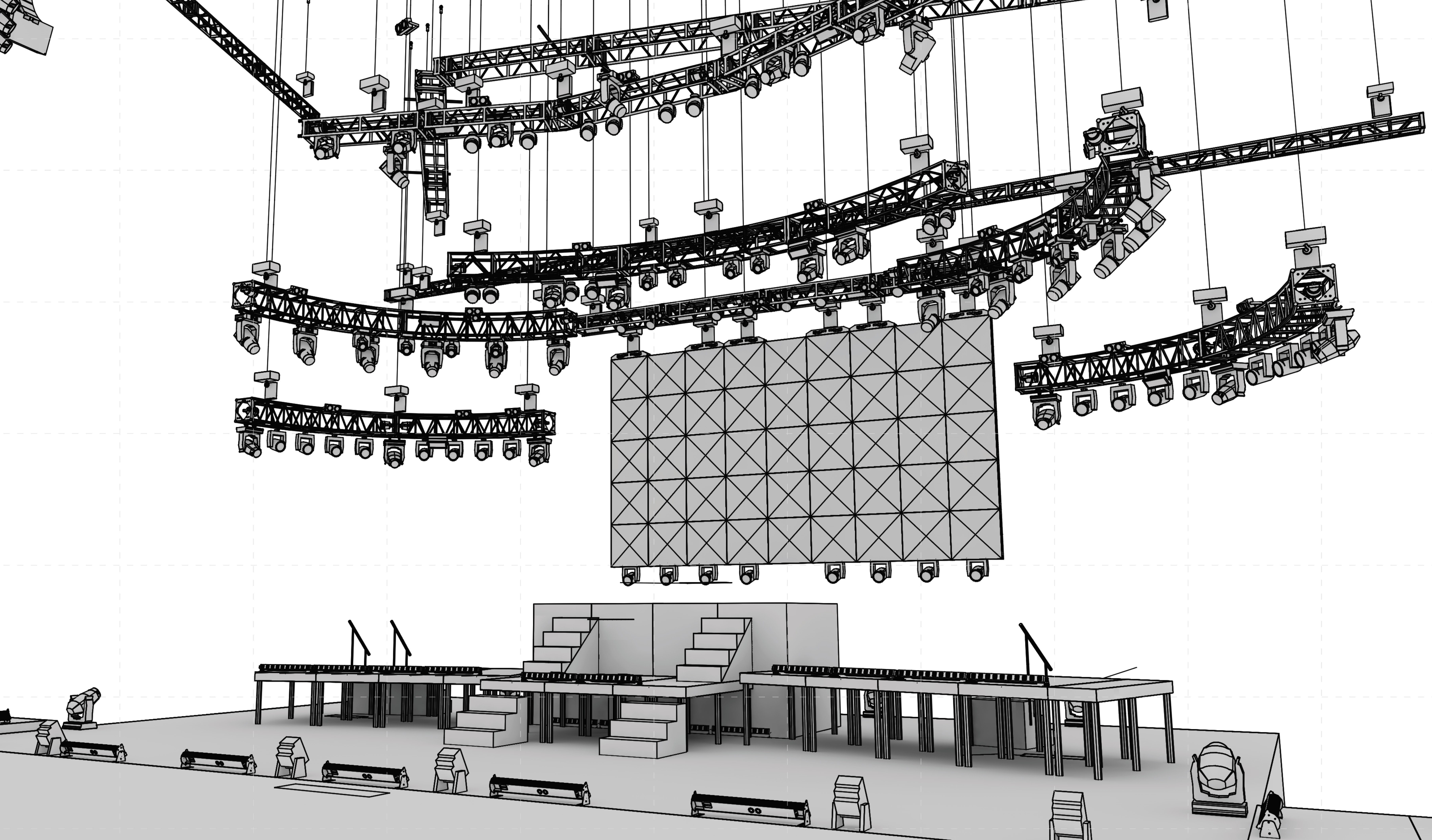
Okay a little goofy here. I have been drawing stage lighting systems and things for quite a while and I have had many times where I get trusses or set pieces going at odd angles to each other. Typically I make a very goofy classing structure to allow me to isolate just the stuff I want to see and do a set view to an angle I want if say I wanted a front or side view of the thing in question. I am curious if anyone else has other methods that might be better for accomplishing this. Thankfully I am working on a semi simple project and I am hoping to play around and find a better method and curious on what others do especially the architectural folks out there. I attached a screen shot of the item in question. This project has 4 trusses running at diagonals making a "V" shape at center. I want to see just the outside trusses on each side. These trusses have a handful of striplights hung at goofy angles and I want to put notations on these lights in a viewport. I want to make a viewport of just the truss shown without showing the other stuff in front or behind. Kind of like a section viewport (which has been one of my work arounds in the past). I want the viewport to basically show the profile of the truss showing those lights. I am hoping there is a way to dictate the starting point of the view like a camera view and an ending point. Also hoping to get this as orthogonal. Anyone have any recommendations?
-
Is there some cool way of having a document put some sort of text somewhere on the sheet that labels the sheet layer name? I have a co worker who uses the date stamp tool and in a perfect world he would like that to have a field in there that displayed the sheet layer name on it. Or maybe a field in a title block that you can link text to a record, but that record value would be the sheet layer name. Or any other potential idea someone has or uses to achieve this. Anyone out there have any good ideas on a way to do this? Matt