Ride
-
Posts
353 -
Joined
-
Last visited
Content Type
Profiles
Forums
Events
Articles
Marionette
Store
Everything posted by Ride
-
Also, where did you find your plywood endgrain texture? I like that one a lot better than the one I'm using...
-
Hmm. I don't see what you're seeing. You have all the sides as separate items, mine only shows 'face override - sides'. I did select auto-align plane, but that didn't add the subsequent faces.

-
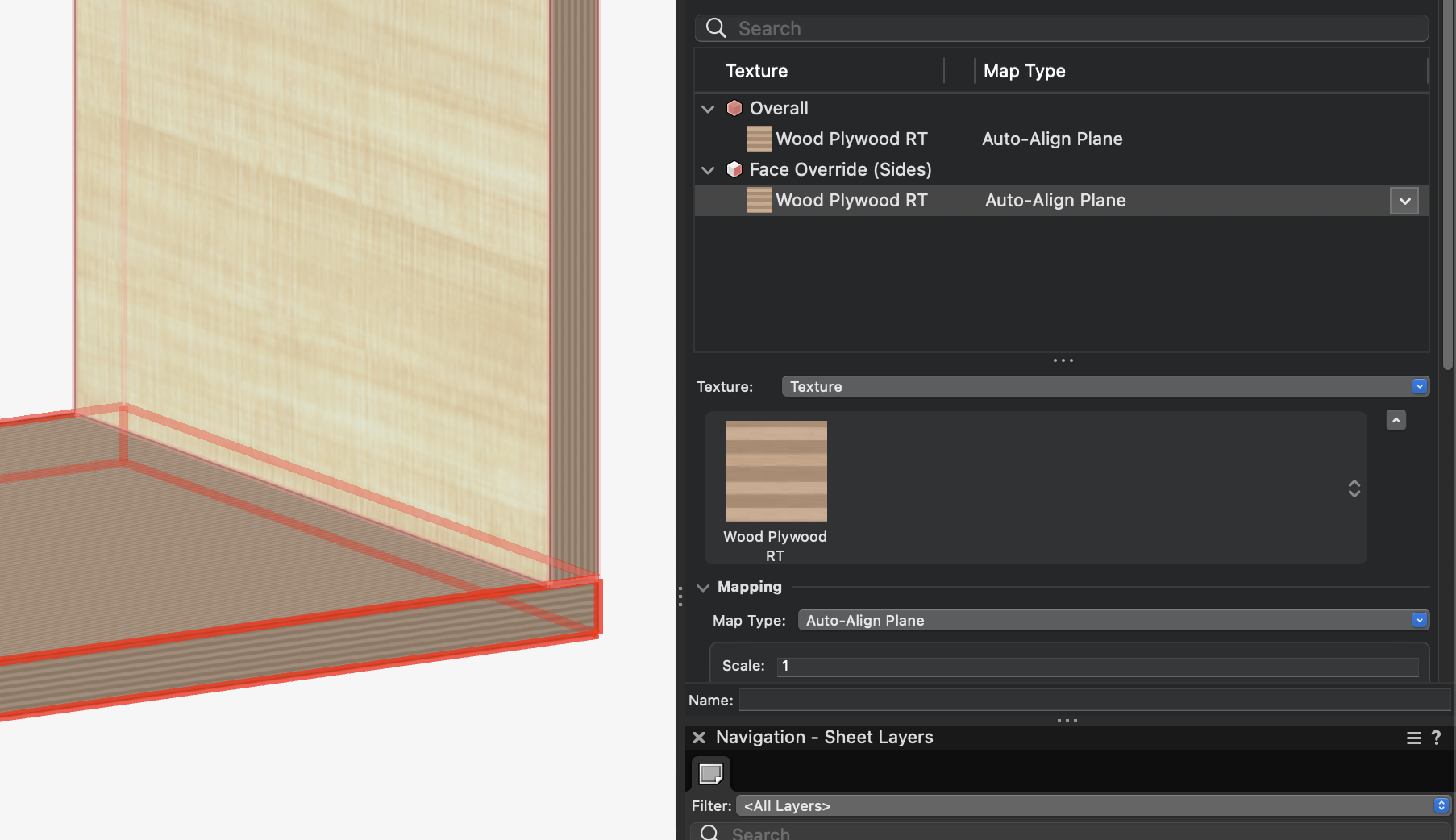
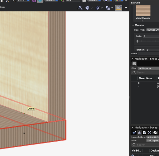
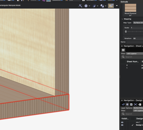
I can get it to work part of the way. See attached screenshots. I'm trying to make the edge of the bottom plywood horizontal, but no matter what rotation I use for the texture, the plies of the plywood remain vertical. How do I force the edge to change orientation?
-
Ok, following up on this thread. The data tag works perfectly. But here's a question - now that the bubble are separate lines, the tag has no fill. So if I use this over a woodgrain hatch, things start to look a bit messy. Any way to get a fill for the bubble?
-
Oops, I need to update my signature, will do it now. I'm on 2022 Architect with InteriorCAD. I can never get the per face texturing to work. Not sure what I'm doing wrong...
-
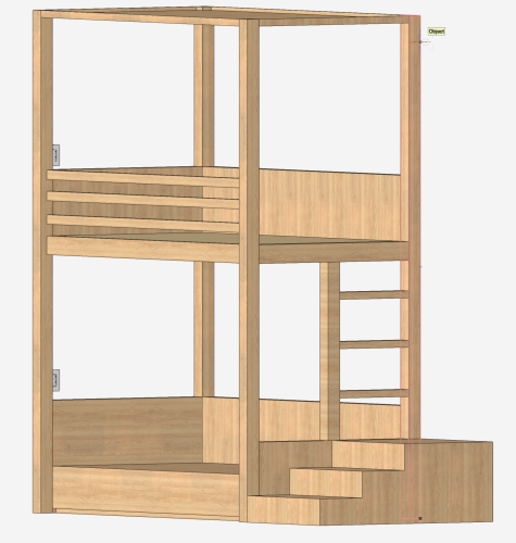
Can someone please explain how to apply a texture to a face of an object? For the life of me, I cannot get the grain directions in wood textures to represent what I actually want. In some cases, changing the rotation of the texture does absolutely nothing on one object, but works on another. It doesn't make any sense to me. Below is a screenshot of a bunkbed that I'm trying to model, but I need to get the grain directions right so I can provide this with my shop drawings. Any help appreciated.
-
Yep. That did it! Thank you. I too spent a bunch of time looking, but couldn't figure out why mine didn't work. So in the end, something simple. But not so simple.🤦♂️ Happy New Year!
-
It is. Here is a file with the data tag. If you have a chance maybe you can take a look? I'm sure I'm missing something simple. data tag sample.vwx
-
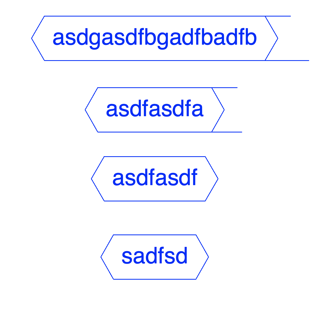
Ok, sorry for the delay on this. I think I have it setup correctly, here are my settings for the lines. But I still get the line extending beyond the side brackets when the text is over 6 characters.


-
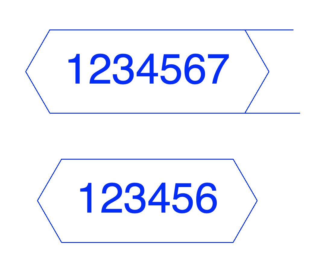
Hmm. This is promising. But why do my lines extend beyond the bubble when the text gets really long? I tried a few different variations on your settings above (including control points of the top and bottom lines), but always the same result. Does your example have the same behaviour?

-
Well I'm very grateful to have gotten this far. And TBH, it's unlikely I would ever have a finish tag that long. But it never hurts to ask! Appreciate the help. This will be a big time saver for me.
-
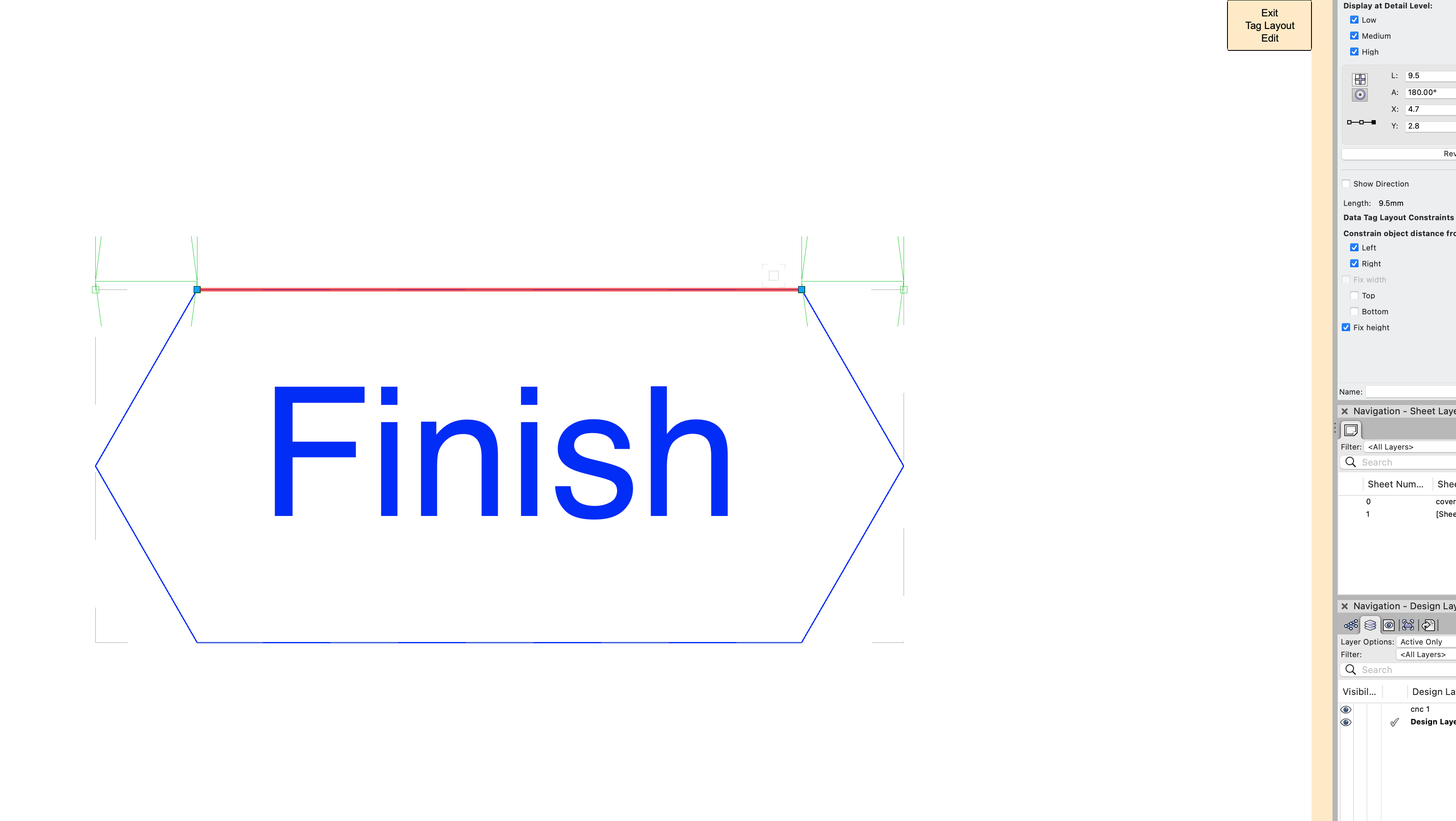
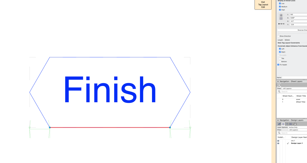
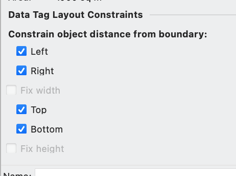
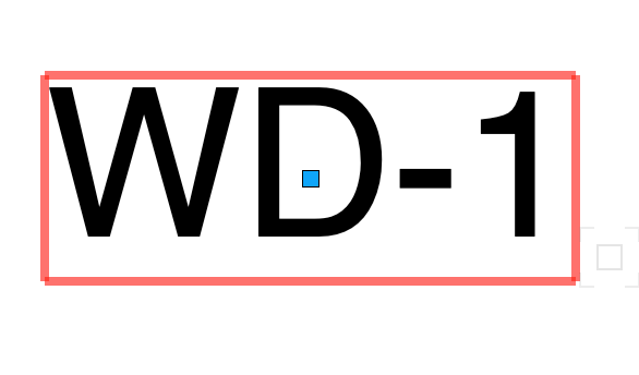
Wait! I got it. Helps if you actually read the instructions. Apply the constraints to the text, not the bubble. Which is great. But last question (I think). When you input a long text note, the bubble ends get elongated. Is there a way to constrain those but adjust the middle portion of the bubble? See attached:
-
This sounds brilliant. But I'm missing something. When I select the contraints, I get light green dimensions around the bubble. But when I finish editing the data tag, I don't have the bubble anymore. There must be somewhere to specify the distance from the boundary - where is it? Thanks!

-
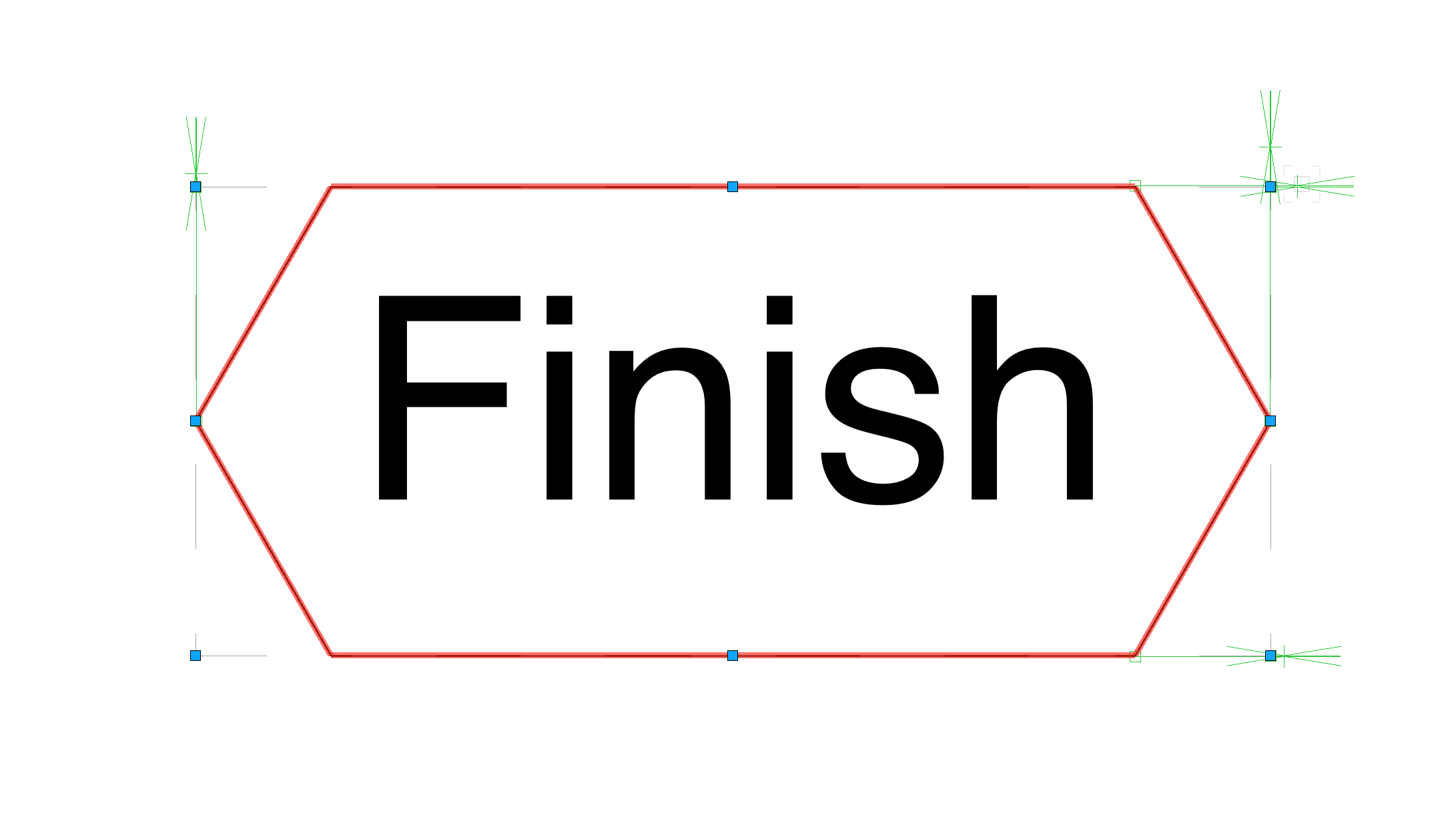
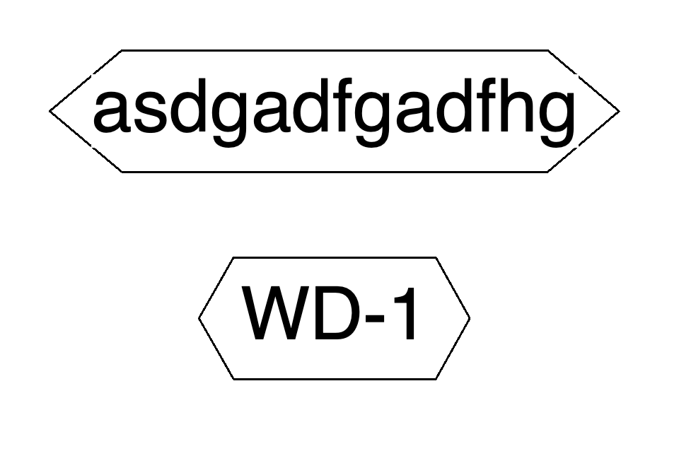
I work in architectural millwork, doing shop drawings, and I'm trying to create a data tag for our finish notes. I have attached an image of a typical finish note/bubble we use. I can create a data tag easily enough, but I don't know how to make the bubble automatically adjust around the text. What I have works fine *most* of the time, but say I have a longer note (such as WDV-01) that some designers use, it runs outside the bubble. Is there a way to make the bubble adjust to text? Or is there a better tool for this? Any help appreciated! Hope everyone has a good holiday season...
-
Yes, that works well too. Thanks. Though I do have trouble selecting either the NURBS curve, or the 3D poly after I draw it. Not sure why. My problem originally is I was trying to use 2D tools for this, which work fine as long as you're working on the actual working plane. As soon as you veer off things don't work, obviously. I need to spend more time getting to know the 3D toolset.
-
Ah ok. I tried to put in 0, and then it wouldn't let me. Thanks - this seems to be working. I knew there had to be a way to do this without multiple extrudes. Appreciate the help!
-
When I use the NURBS curve, all the vertices are curved. It won't let me put a value less than 3 in for the radius. What am I doing wrong? There must be a way to draw this in one go, in 3D.
-
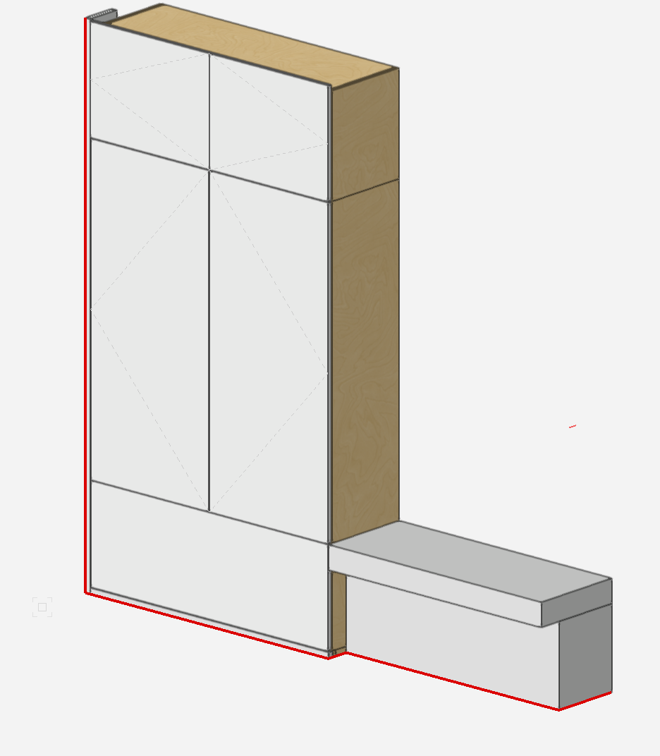
Hi. I'm trying to draw a small trim around some cabinets, and a bench seat. The trim is a simple 1" square profile, and I would like it to follow the red line shown on the attached screen shot. I feel like I've done this before, but I can't seem to get it to work now. What layer/working plane do I need to allow me to draw the path of the trim, and then extrude along path? I've tried setting the working plane to the face of the doors, but as soon as I try to draw the path back to the recess of the bench seat, things fall apart. Do I need to draw each section individually, and them combine, convert to Nubrs? Any help appreciated.
-
Well maybe I spoke too soon. It works on the design layer, but my in my viewport the lines are back. Will work on this some more.
-
Yes! This worked for me too. Thank you all. So helpful.
-
Ah ha! Yes it does. I have never seen that type of 'join' before. I only tried it on one instance, but it worked. I use simple walls with only one component as I don't need to show wall construction (this is for millwork shop drawings). Could there be something in my wall construction that is making that line persist? Either way, happy to have a solution for this. It was getting really annoying. Thanks for the help.
-
Well that's unfortunate. I've been trying to figure this out for a long time, and now I know I'm not the only one. It makes my drawings look messy with all the extra lines. Is this better in 2022? I'm not using that much these days - even though I have it. It has some weird graphic issues going on with viewports. But that's for another post.
-
No, I'm using uncapped mode. Thanks for the reply.
-
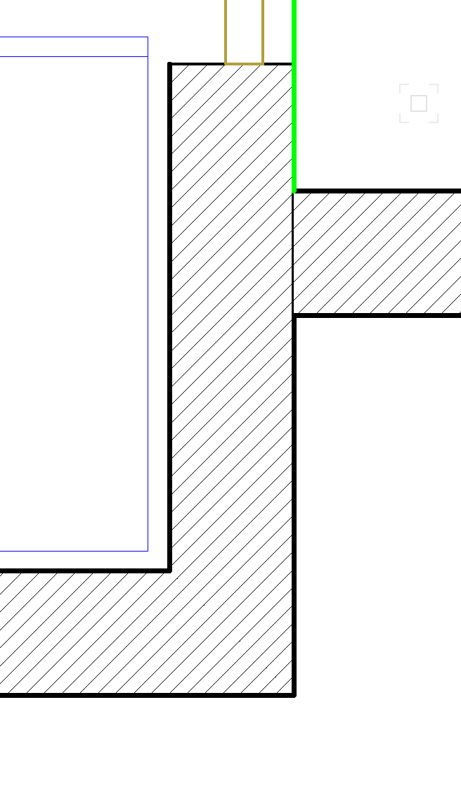
Is there a reason why my T wall joins still show a line at the joint? This doesn't happen with the L joins. Thanks
-
Any updates to this? Though it wasn't a cabinet object, but a solid that I modelled. They were nightstands, so there was one on each side of the bed. One rendered properly, but not the other, this in shaded view, in a viewport. It rendered fine in the design layer. This is using VW2022, SP3. I haven't updated my signature yet as I'm still using 2021. I have 2022, but so far I don't like it at all. Lots of hatch scaling issues in viewports, and every dimension I place takes 1-2 seconds to register before I can carry on dimensioning.