


Ride
-
Posts
353 -
Joined
-
Last visited
Content Type
Profiles
Forums
Events
Articles
Marionette
Store
Everything posted by Ride
-
Yeah this is brutal. I accidentally included a couple sheet layers with renderings on them and now I wait.... I don't want to force-quit as I have other drawings open that may have unsaved changes.
-
I would really like to know what's in store for 2024. I hate buying the services select for 2 licences, not knowing if I will need or want the 2024 improvements.
-
Ok thank you for the reply. I guess what I was ultimately confused on was that you could keep getting updates, even though you're not on a subscription plan. I guess the most prudent move is to continue on with service select. The rate at which versions of VW become unsupported means not staying up to date ends up just costing you more later, without the benefits of the new features along the way....
-
I have VW 2023, and plan to use this for a couple years. Is it worth continuing on with service select, or should I let that expire? Now that VW is a subscription model, won't I automatically be on the subscription plan if I upgrade from 2023?
-
Not meaning to hijack this thread, but maybe some of the info here will help others. I have been in touch with Brendan, and he's been super generous in offering his help to get me going. The hold-up has been on my end as I've been far too busy to spend time on getting this up an running, and I've been putting him off. But the reality is not getting this set up will ensure I stay too busy to set it up. My machine is a Biesse Skill GFT1224. Right now I'm writing all the cabinet part files in Biesseworks, and nesting in Biessenest.
-
Haha, thanks. I need tons of advice. I love InteriorCAD, couldn't live without it. But I also find that it is not intuitive, or easy to figure out. My end goal is to be able to use it at a level to export fully modelled cabinets direct to my CNC. I am getting there slowly as I work through things like these hardware grids. I'll try that Discord link again soon and let you know if it's expired...
-
This is super helpful. I really need to get my discord account setup. I literally just submitted a ticket to Extragroup a few days ago asking for a tutorial on custom grids. They are not at all intuitive. Thank you @Blinkglitter
-
How to buy an InteriorCAD update?
Ride replied to Ride's topic in 3rd Party Services, Products and Events
I don't know anything about discord, but I'll look into it and DM you me details soon. Thanks -
How to buy an InteriorCAD update?
Ride replied to Ride's topic in 3rd Party Services, Products and Events
Yes I would be interested. Keep me posted on any progress.... -
How to buy an InteriorCAD update?
Ride replied to Ride's topic in 3rd Party Services, Products and Events
I finally heard back from Sven. It looks like I will be able to purchase the upgrade soon. I'll update again once it's finalized. Looking forward to trying out 2023... -
How to buy an InteriorCAD update?
Ride replied to Ride's topic in 3rd Party Services, Products and Events
And still no response.... Has anyone else been able to purchase InteriorCAD 2023? -
I am having no luck in contacting Extragroup. I've emailed a couple times, and even submitted a ticket asking to upgrade to 2023. @Stephan Moenninghoff, who do I need to contact to purchase the upgrade? Thanks
-
@Benson Shaw, thank you for that video and explanation. I haven't tried this yet but will shortly, but I think you gave me everything I need to get my loft to work. @VIRTUALENVIRONS, what was not clear with my original request? I had two NURBS surfaces that I couldn't loft to make a solid. I needed more information, such as they need to be NURBS curves, not surfaces. That was probably the key bit I was doing wrong. I attached my file so anyone could open it to see what I was working with. Vectorworks is not very forthcoming with clues as to what's wrong when an operation fails. And I don't find the VW help very helpful.
-
I just can't get the loft to work. I tried again, and I don't have directions, but I do have "Normal". I adjusted those so the arrow pointed the same way, but still the loft doesn't work. I can't select my NURBS surfaces to create the loft.
-
Wondering if someone is able to create a loft surface between these 2 NURBS surfaces. Can you explain the steps needed to get this to work? I can't seem to get it. Thanks in advance for any help. loft surface question.vwx
-
Of course. So obvious. Sometimes you can't see the forest for the trees. Thank you.
-
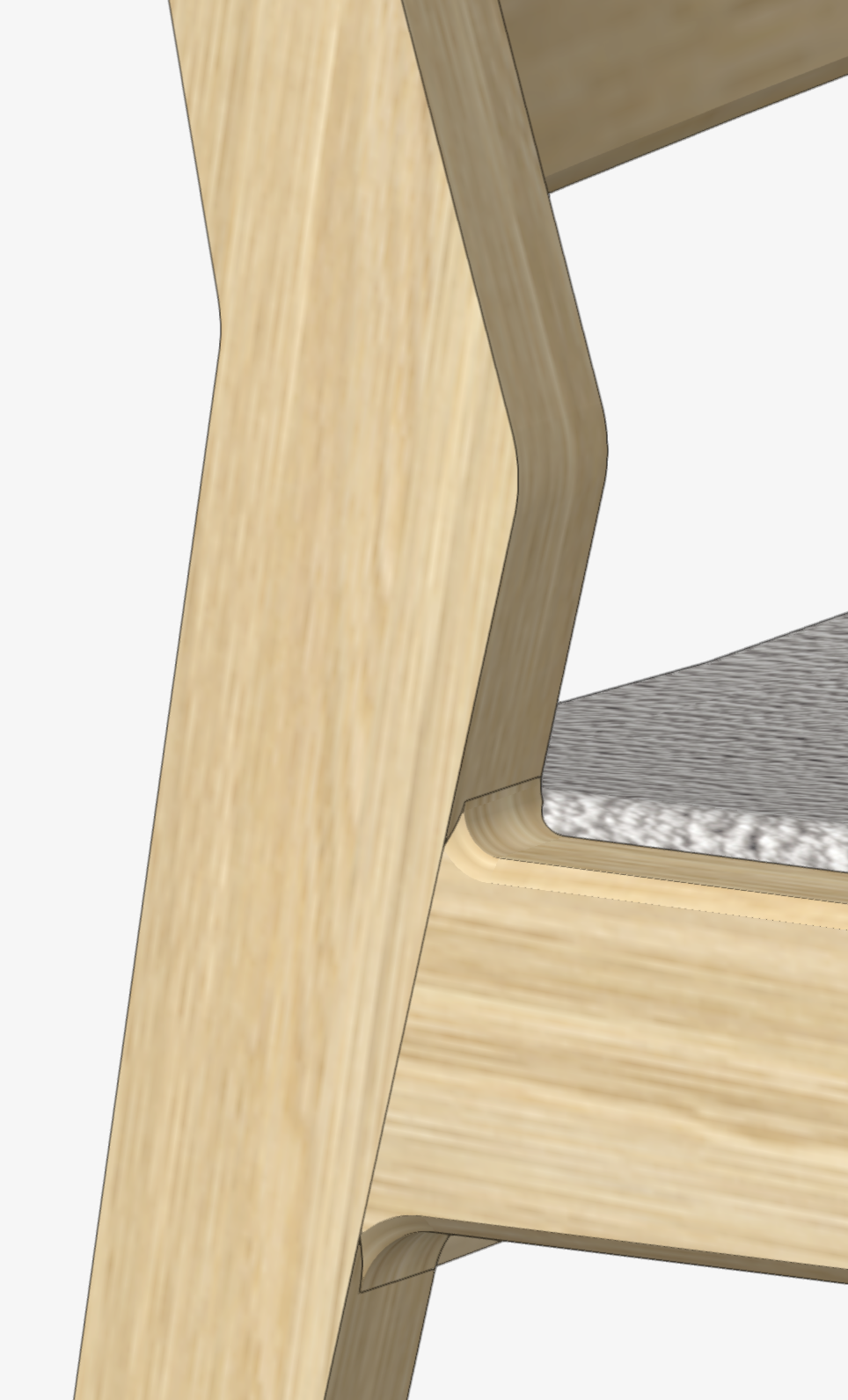
I am trying to model a dining chair, where the seat rail meets the back leg/seat back. How do I chamfer the joint to show properly? In the picture below only the rail edges are chamfered, but I want this to continue on the back leg/seat back as well. Is this possible? I though of making the leg and rail in one object, and then adding a 0.1mm surface to the face of the rail to show the change in grain direction. Is there a better way? Thanks
-
I used the method as suggested by @Kevin McAllister, and so far it's working out well. We have built one of the walls now, working out any little glitches, and the rest are going into production next week. I bevelled all the cladding edges, except at the top and bottom where I ran the skeleton wall full height. So those top and bottom bevels are left square and trimmed off with a flush trim router bit. I'll post up some photos soon.
-
Ok. I got it now. I was actually using your file to practice creating the lofted surfaces, so they were already NURBS curves. But it was a simple order of operations thing. Gotta select things in the right order to get it to work. I think this is the way forward. Appreciate the help! I'll report back once this is a real thing made out of MDF.
-
@Kevin McAllister, your example seems perfect for what I'm trying to do. But can't get the loft surface to work. I assume I use 'no rail mode', but it doesn't work for me. Can you walk me through how to create the loft surface?
-
Thanks to all for your replies. My original object was a simple extrude, that I lopped off the faceted faces with the split tool. Once I had the outside shape, I used shell solid to give me my 3/4" MDF panel thickness. I think I might have been part of the way there with my inside and outside faces, but I think what I was missing is these needed to be NURBS surfaces before I could loft them together. I will read through all the suggestions a couple times, but @Kevin McAllister, your method above seems like it would get me there. I originally tried rotating the object so the joints would align with an x, or y axis and then split it along the lines, but this is a very cumbersome way of doing things. I will report back once I've tried a few options. Again, thank for the replies thus far.
-
Hi. I am trying to create the MDF panels to clad a skeleton to make this shape. I would like to model each surface with the correct angles and bevels, to communicate that with the joiner who will be doing this on a table saw. I thought the best way might be to extract the inside and outside face, and then extrude one to the other. But not sure how to do that. In the screenshot attached, you can see the overall shape, and also the inside and outside faces of one of the panels. Or is there a better way? Thanks

-
Thank you!
-
Ok I just started a new file with a new part, and its working fine now. I don't know what I was doing wrong before but glad it's working now. Thanks for the help. I clearly need to adjust my selection colours though, I can't tell which face is being highlighted which makes it difficult to know what is being changed. Again, thanks for the help. This has baffled me for some time now.
-
Ok, I'll try again and post back soon. And yes if you would be willing to share the texture I would be grateful. I'm always trying to make my models more realistic. It helps when I put work on to the shop floor to have some accurate 3D perspectives of the final product.

