


Ryan Russell
-
Posts
55 -
Joined
-
Last visited
Content Type
Profiles
Forums
Events
Articles
Marionette
Store
Posts posted by Ryan Russell
-
-
I think that not incorporating what's necessary for construction of Single Family Residential Dwellings is a huge miss.
And I find it amusing that Architects continually pass the responsibility onto someone else!
For those who hold a professional license, they most certainly have missed the directive of "public safety".
Knowing all the details of any project is paramount, and I think that VW should reflect the same.
-
@Matt Panzer - Why is the FRAMING process not more important for Vectorworks?
Especially when you consider current IRC requirements for braced wall panel design, this seems to be a much-needed feature from the VW team. Architects & Home Builders are now being required to understand how the framing works on the house not just for design sake, but also that of required calculations, takeoffs, and load analysis (both seismic and wind load paths).
Others have chimed in that they do not want the WALL TOOL to be modified as it may affect their workflow, and I think that makes sense to not tie this to the WALL TOOL.
Furthermore, others have posted that the PROCESS I am seeking is the job of an Engineer. I like to be knowledgable and in control of my projects, and would hope the Vectorworks team can see value in improving the software to assist those in the field I have said earlier... I welcome a conversation with the programming team that could assist in developing methods or processes on how best to move forward with the development of a functional solution. It would be really nice to replicate the entire process for how Residential Construction happens in the field. And when you consider that the LOAD PATHS are transferred from the Roof System, down through the Walls, then into the Foundation it makes the FRAMING absolutely crucial to have correct when constructing a Digital Twin.
So perhaps we just need another tool to be developed that can be tied to the WALL TOOL and update as changes are made to the WALL TOOL.
Other things that would be nice to have...
- inclusion of braced wall methods
- inclusion of options for insulation methods
- ability to shift from 16" to 24" on center framing
- ability to select individual corner styles for common framing methods, and have multiple methods in single system
- insertion options for studs (sizing (2x4), (2x6), (2x8), materials (dimensional lumber, LSL studs))
- implementation similar to 2 point click for Cabinet Plug-in for poly line insertion along FOUNDATION perimeter
- inclusion of options for mud sill, untreated plate, treated plate
- compliance with minimum of IRC 2018 code
Future improvements...
- APA Wood Calculator integration
- Material takeoff
- IRC enhancements & required changes to Braced Wall Panel design (Chapter 6) for more current iterations of code (2021, 2024).
- Potentially integrate Roof, Truss, Ceiling, and Floor into this tool for more accurate modeling capabilities
-
2 hours ago, Tom W. said:
Ok but the Wall Tool is hardly 'a legacy tool which hasn't been updated for some time'...
Well, what I would like to get down to is having the wall tool smartly illustrate accurate framing, both demonstrating traditional framing and modern advanced framing methods.
Given that we’re now being asked to conform to current IRC standards, I would think that this is now more important than ever to accurately model. Not solely for design purposes, but also for understanding the engineering, and accuracy of takeoffs for materials.
Software has always been designed to solve problems due to the speed the machine provides over humans. It would be a warm welcome to have this incorporated into VW.
-
And I also have the latest SDKVW(750359)
-
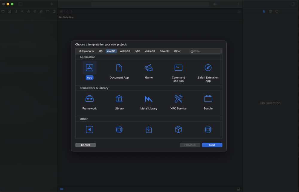
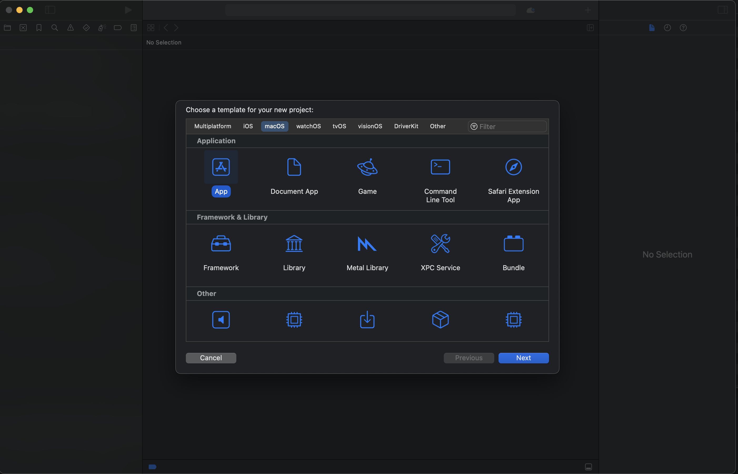
This is the start dialog window on Xcode 15.2, what's the next step?
-
Can anyone advise as to what's the best practice for a new setup on a Mac for SDK 2024?
The install notes are dated to 2015, and are of little value to Modern Xcode.
-
WALL TOOL, my entire thread is/was started based on what is being done here http://design.medeek.com/resources/resources.html for Sketchup.
It's pretty amazing what this gentleman has done, and I would like to incorporate these ideas into VW.
While some would say this is overkill, I completely disagree. After all the more complete the digital twin becomes, the more useful the tool would be in your design arsenal. And can you imagine if it would rebuild on the fly like it does now when you modify the WNDOW / DOOR objects?
-
It would be really nice to have the WALL TOOL revised to reflect the parameters listed below:
- Wall Justification (required) - allows the user to define the wall placement relative to the line used to draw the wall.
- Wall Header Height (required) - default header height for openings in inches.
- Stud Size (required) - pick from a selection of standard stud sizes (nominal dimensions).
- Stud Spacing (required) - center to center spacing between studs in inches.
- Stud Direction (required) - allows the stud layout to be from either the right or left.
- Start Corner (optional) - specify the corner configuration at the left end of the wall, this parameter is ignored when auto-corner configuration is enabled.
- Start Angle (optional) - specify the corner angle at the left end of the wall in degrees, this parameter is ignored when auto-corner configuration is enabled.
- End Corner (optional) - specify the corner configuration at the right end of the wall, this parameter is ignored when auto-corner configuration is enabled.
- End Angle (optional) - specify the corner angle at the right end of the wall, this parameter is ignored when auto-corner configuration is enabled.
- Top Plate Qty. (required) - number of top plates the wall is constructed with.
- Top Plate Thickness (required) - thickness of the top plate(s) in inches.
- Bottom Plate Qty. (required) - number of bottom plates the wall is constructed with.
- Bottom Plate Thickness (required) - thickness of the bottom plate(s) in inches.
- PT Bottom Plate (optional) - specify a pressure treated bottom plate
- Wall Group (optional) - wall panels can be grouped and then later modified in a batch mode.
- Wall Framing (optional) - sets the framing mode of the wall panel: 2D, 3D (No Framing), 3D (Full Framing), ICF or CMU (concrete block).
- Advanced Wall Options (optional) - enables advanced options for the wall panel (ie. sheathing, gypsum, cladding, insulation, trim, hold downs and blocking).
- Additional parameters and options are available for windows, doors, exterior trim, insulation, sheathing, cladding, gypsum, holdowns and interior trim.
I gather from reading other posts that the WALL TOOL is a legacy tool and hasn't been updated in some time. I would welcome a conversation with VectorWorks and would entertain assisting in reengineering that component of the software directly. Please feel free to reach out.
-
On 7/30/2019 at 4:30 PM, JuanP said:
Thank you for feedback, I just submitted this wish under the following: VE-999656
Even though this is an internal # and might not mean much to you all, It will help me/us to keep you all informed of any progress.
JuanP, can you update on any changes since 2019?
-
 2
2
-
-
8 hours ago, Tom W. said:
I model my strip foundations as Walls + have never had any issues doing it like that. I estimate their size/depth initially then adjust them once I've had the SE input.
I used to use the Wall Framer command for timber framing but now do it manually using a series of hybrid symbols I created. I find this the same amount of work, after I've gone through the Wall Framer model + tweaked everything, plus everything is automatically in the right class with the right attributes + I get the Top/Plan look I want. But that's not to say I wouldn't be very grateful for a properly developed automated solution. See:
It's funny because that was the exact plugin I was referring to in my original post!
-
2 hours ago, line-weight said:
Surely foundations ought to be designed by a structural engineer, and for the specific site conditions & local building regulations/codes... rather than by a plugin?
not that I don’t agree, but I would like to be able to accurately model it. -
All,
Sketchup seems to have some time saving plugins that have been developed for Residential Construction for Foundations and Framing.
I am wondering if someone knows of anything that can benefit a Residential Single Family Construction workflow?
Granted we now have Cabinets that can be modeled and some scripts that have been written for creation of tubs, toilet, and sink placements, I am still struggling on understanding why Vectorworks doesn’t specifically cater more toward this workflow, etc..
Perhaps I am just not looking in the right place?
Thanks in advance your time and support.
Ryan Russell
-
Has anyone compiled a master resource list for learning VW that offers all the content ever published by Nemetschek & Partners?
-
Is it me or did VW2023 have a popup window where you could directly code/run a Script without it having to be physically imported?
I cannot find the same functionality in VW2024, it appears that all new items have to be essentially side-loaded as a plugin.
-
All,
I’m wanting to develop some plugins that can help our Residential Construction firm to reduce the time we are currently spending on repetitive tasks in our drawings.
At present, I’m curious as to whether the legacy information on VectorScript included in VectorScript Language Guide is still relevant for VW2024.
Conceptually, I’m trying to attack framing implementation, estimation, and work my way out from there, including IRC Building Code compliance.
If you have any input on logic or process, I’m all ears. Thanks for your time in advance.
Ryan Russell
-
On 3/14/2024 at 7:14 AM, Tom W. said:
I use hybrid symbols for my electrical devices.
They look like this in 3D:

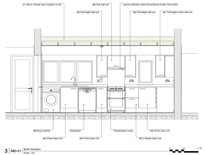
Like this in hidden line section VPs:
And like this in Top/Plan:
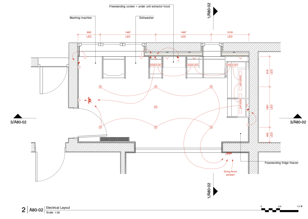
The polylines representing the switching for the lighting is drawn separately on its on Design Layer (I prefer to do it on a Design Layer rather than in VP annotations because then I can show it in multiple VPs if I need to).
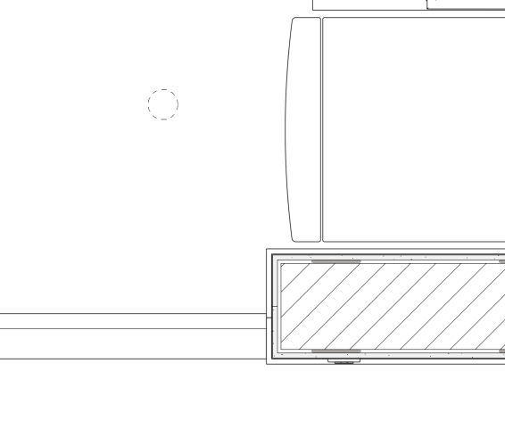
The symbols actually have two 2D components separated by class: the red schematic representation shown above plus a 'realistic' representation which I display in standard non-schematic plans. Here you can see the LED downlighters are represented by a dashed circle + there is a 3-gang light switch on the south side of the nib wall:
The 3D component of the symbols are set to insert at the correct height off the floor so the symbols can be inserted in Top/Plan very quickly + easily. The symbols incorporate 2D loci so I can insert them the correct distance from each other side by side on the wall.
Lastly I have a Graphic Legend set up as a key:
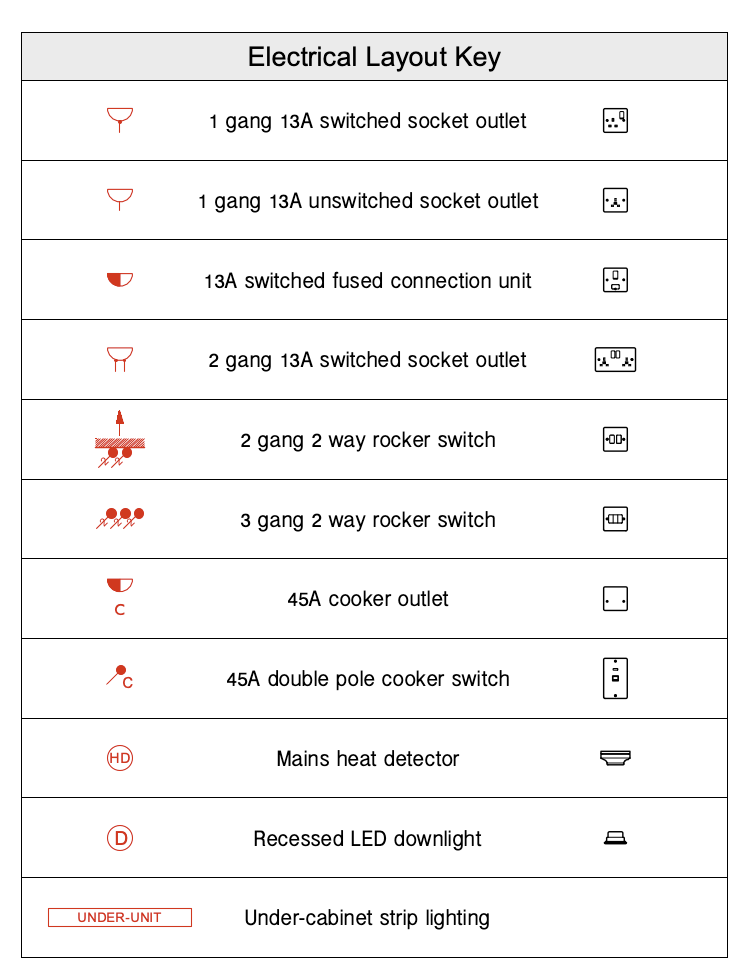
Works well for me.
Very nice!
-
1
-
-
All,
I'm curious as to whether or not you'd benefit from a Ceiling Component that worked in conjunction with the VW Wall Component tool.
Specifically one that allowed for barrel shape, length, depth, and being a component, would allow for takeoff data & IFC materials. Yes, you can define the area, extrude, and subtract solids, and be left with a decent working barrel ceiling, but it'd be nice to have something that could help account for object conflicts and directly work with the Wall Component.
I'm finding that when building a digital twin, this embellishment is an often used item in our toolkit, and it makes it difficult to accurately account for materials when I cannot target the underlying components involved. Also, given that now we're seeing municipalities become more stringent on 'Construction Drawings", providing a richer level of detail would be beneficial!
Also, thinking more globally, instead of using the choose 'slab from objects', would it also not be of benefit to have a dedicated (Residential) Ceiling component? One that could allow for a push / pull(?) of the ceiling, etc.?
- Ryan
-
2
-
-
Vectorworks Team,
It is my understanding that to create a barrel ceiling, we need to identify the area, create an extrusion, and then subtract solids. While this is fairly straightforward, it doesn't account for conflicts with objects in the wall components. Is there anyway that those of us in the residential construction sector could see a Barrel Ceiling Component be engineered at some point? This is a fairly standard design element that seems to be overlooked at present & would be a tremendous asset to help those who use VW Architect in their workflow to better model for more accurate takeoffs, etc., in my opinion.
Also, what about coffered and/or tray ceilings? I know the current method of ceilings is to define your area, then create an object from shape, choose "Slab". But for those of us who do Residential Construction, we're left building our structures via piece by piece. It would be nice to have a 'component' made that would work in conjunction with the Wall Component.
And when you consider that now we're seeing "Construction Drawings" that now need to reflect more stringent code conformity, it would be nice to have a view into the model where we could in effect alter how the studs function in the wall itself. The ability to determine within (OIP) how to terminate the ends of a stud wall (2 stud corner, 3 stud corner, 4 stud corner, etc.) would be a game changer for me.
We do extensive work and a deeper degree of details than most, and feel that being able to provide this information via software would greatly increase and speed up our workflow.
Thanks,
Ryan Russell,
Rick Russell Homes, Inc.
-
All,
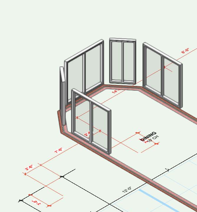
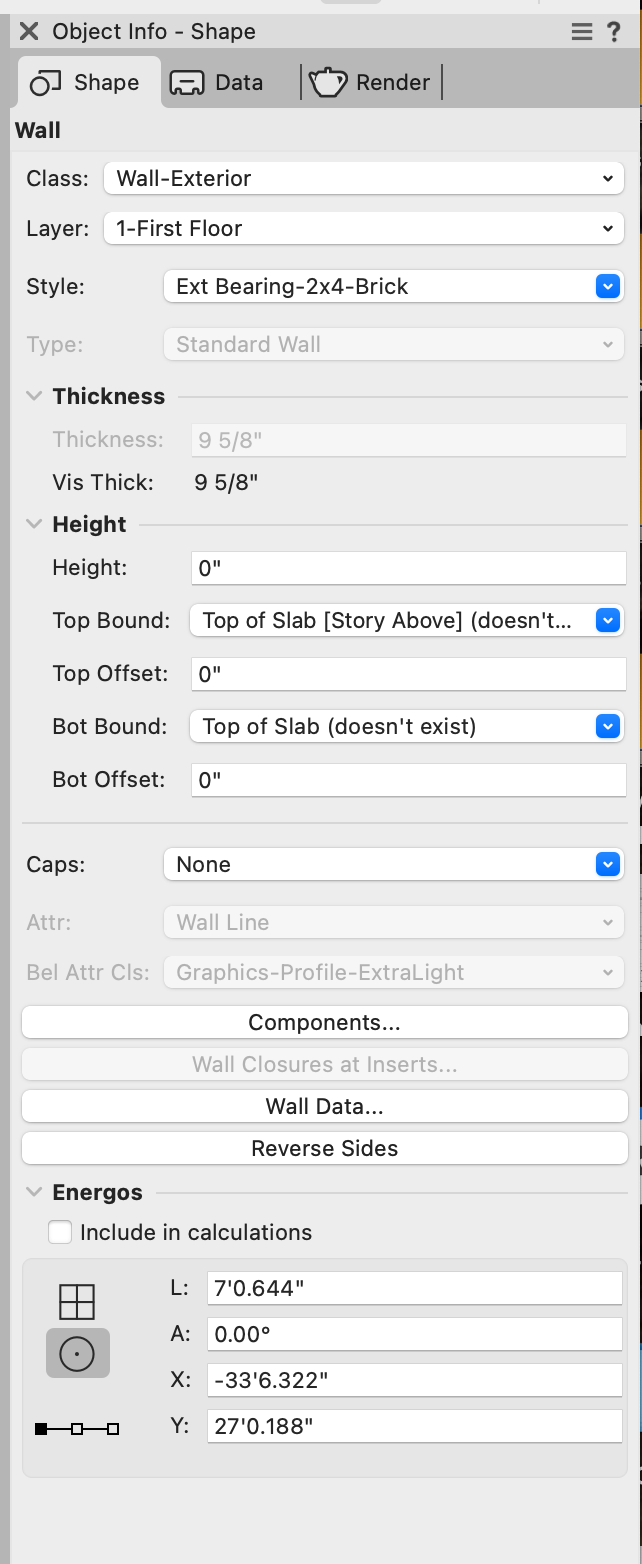
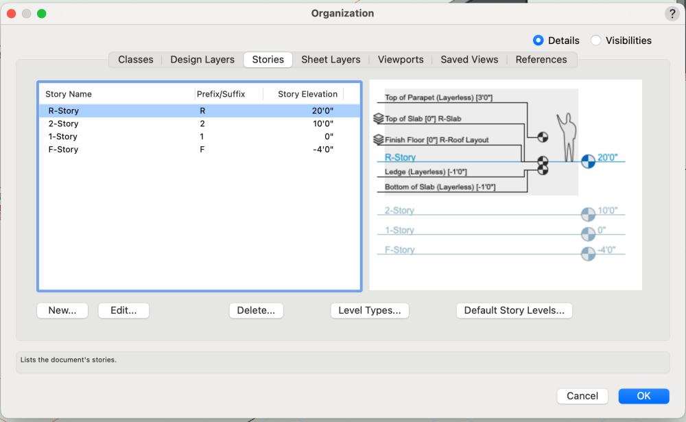
I have been working in a recent file where the Exterior Wall Component has somehow lost its height display.
It has doors & windows that reside within the component and their placed positioning hasn't changed, but the walls themselves fail to span the distance of the previously assigned area.
Again, it looks like the 1-Story configuration is giving me fits.
I have provided example of what I am seeing on screen in an isometric view, along with the OIP panel, and the STORY Organization data.
If anyone can save me, it would be greatly appreciated.
- Ryan Russell
-
Is anyone using Twinmotion and have you paid for the upgrade to the 2023.2?
Or is VW handling all of your rendering needs?
Just curious, because I know previously VW & Epic had teamed up to offer a license to VW users and was looking for input on the latest version.
Is there a discount available?
-
When designing a residential single-family dwelling that must adhere to IRC2018, how are you accounting for J-Bolt bottom plate foundation anchors?
"2018 International Residential Codes (IRC), call for minimum 1/2-inch-diameter anchor bolts. These bolts must extend 7 inches into the concrete and be spaced no more than 6 feet on-center. In seismic zones, these basic requirements apply with the addition of 3-inch-square plate washers."
With the understanding that a decent Foundation Contractor should adhere to local building practices... how should any VW user establish a BEST PRACTICE in respect to Construction Drawing coordination while ensuring quality controls are implemented? Is there a generalized process for J-Bolt anchors to be included on a Foundation Plan, or do you think that this is overkill to provide this level of detail, given the importance that Anchor Bolts have given their respective role of inclusion into Braced Wall Design?
-
All,
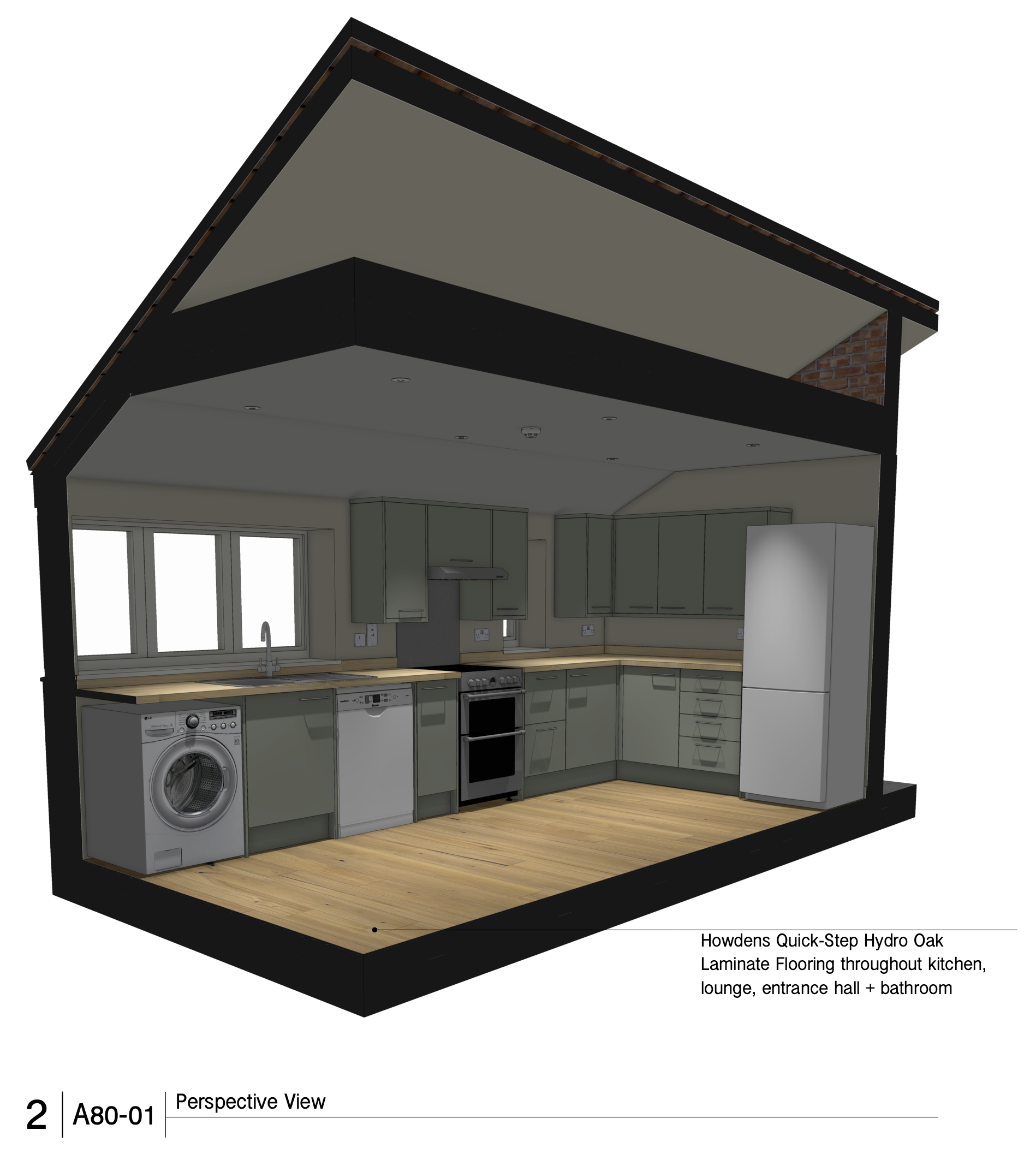
I am presently working on a model for a planned residence and I would like to be able to accurately estimate the amount of split block that will be required to complete the home.
Following is a previous example of the Split-Block on a residence we constructed many years ago.
We are planning on using CMU Split Block that has the following dimensions 16" (length) x 2 1/4" (height) x 4" (depth). In my travails, I have attempted to modify an existing CMU block texture and material by selecting one that is similar from the VW Library > Visualization > Materials and importing it directly into my working folder. I have included below a screen grab to demonstrate the less than ideal rendering.
I am seeking any sage advice that more experienced users can offer on how to improve the object display and to make it look more like the end result.
And since I got my hand slapped for previously not including enough data to help others help me, I can going to include more screen grabs to help in that endeavor.
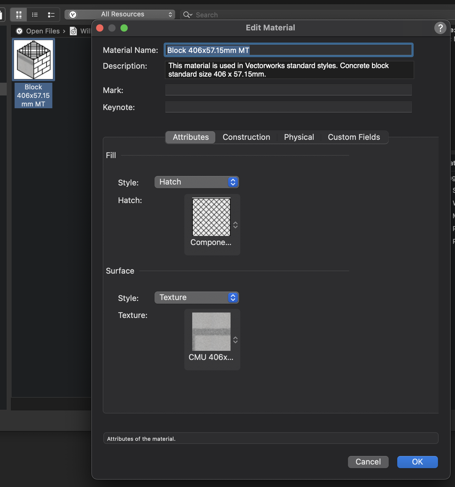
Below the first screen grab is material detail. Not certain about the settings as my render / object view is off.
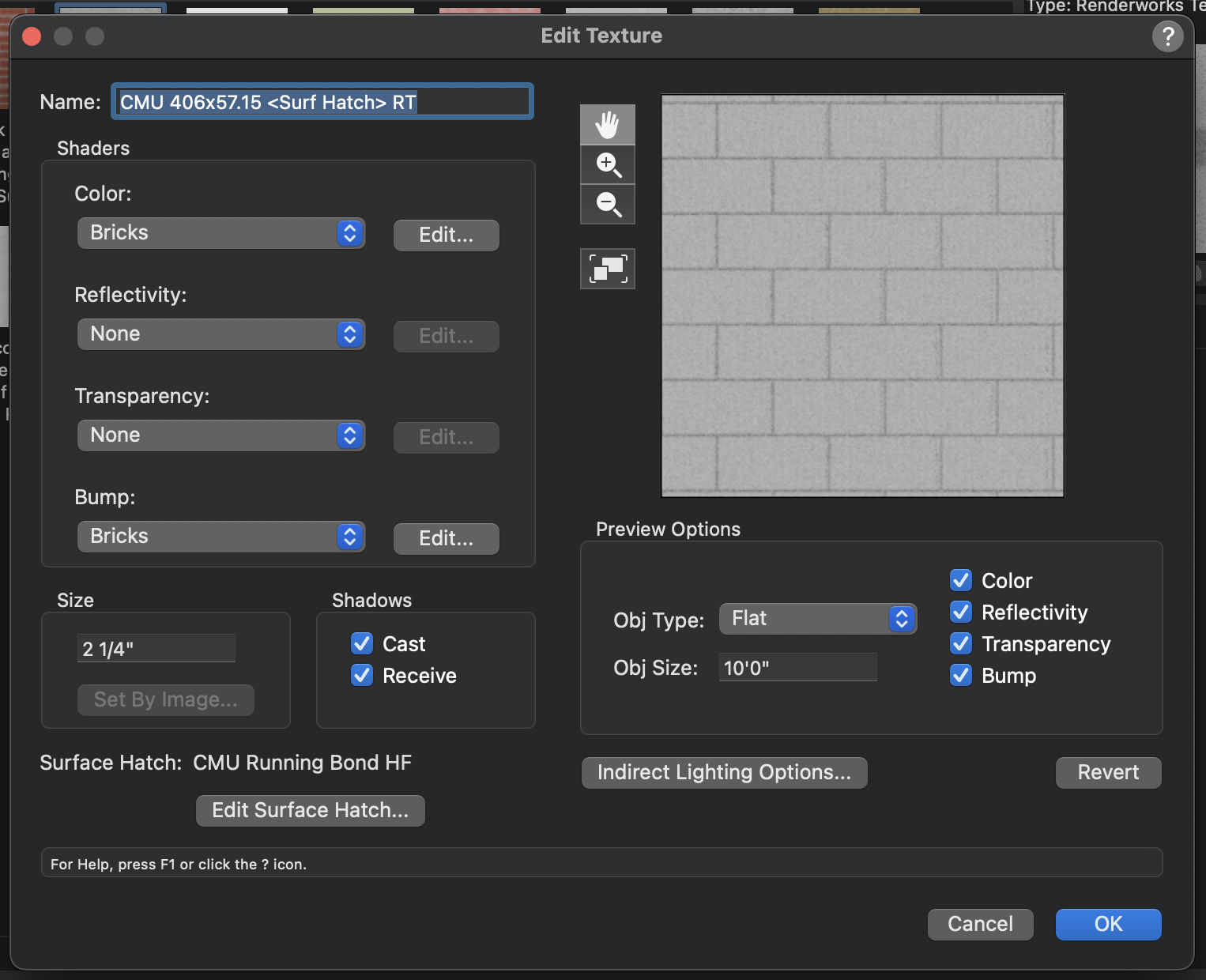
And lastly, the final screen grab is my texture for the CMU block with my settings, they may be completely wrong, but alas they have been included.
Once I figure out how to correctly assemble the material/texture correctly, I think the estimation aspect should be smooth sailing, but I'm open to any suggestions or advice that you may be willing to pass along. Thank you so much in advance for your assistance in this matter!
- Ryan Russell
Also, if I need to provide more data, fire way and let me know what you need.
Material Details (Not certain if these settings are correct - based on the render)

Texture Details (Not certain if these settings are correct - based on the render)

-
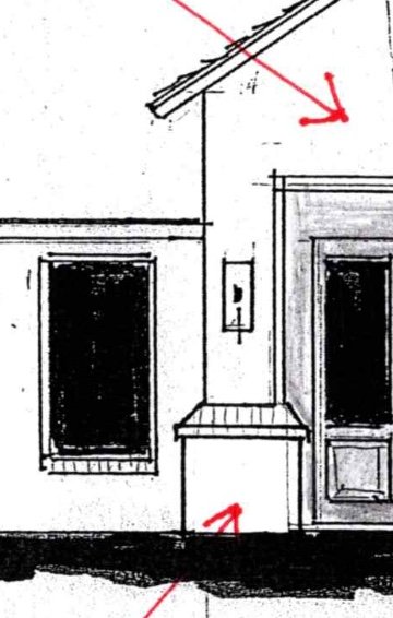
Yes that is the general profile.
-
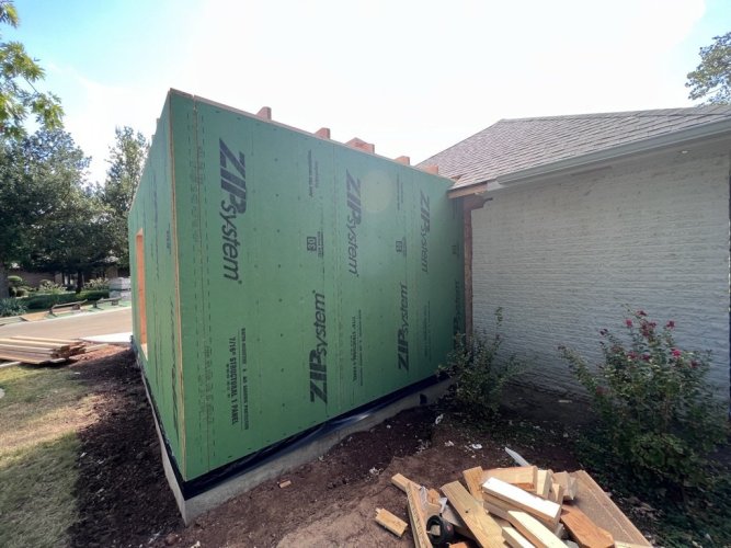
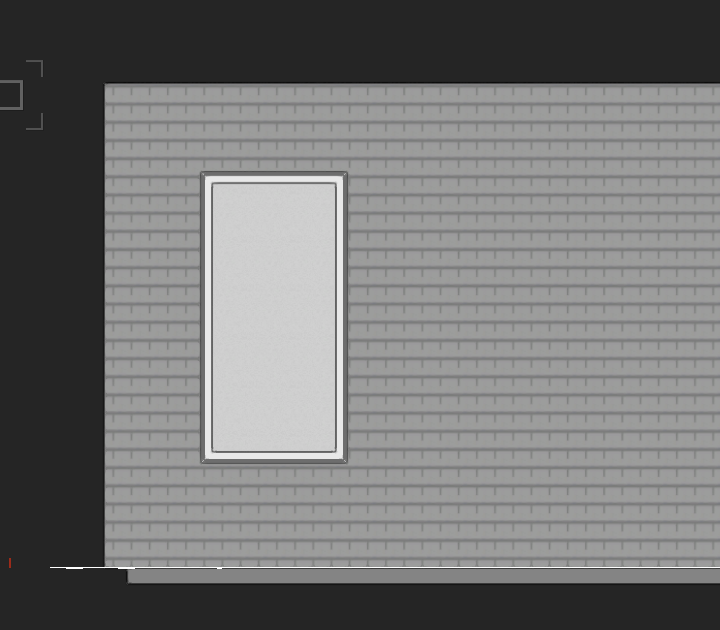
All,
I'm trying to figure out the best way to create a "brick pedestal" like the image below where the column flares out at the base.
And I'm also trying to determine what is the best method for having a component show multiple textures. Again, say for example, that the entry way was partially stucco and partial brick. Thanks in advance for your time and assistance.
- Ryan Russell


Process…
in Architecture
Posted
http://design.medeek.com/resources/resources.html
Look at all the tools developed here for Sketch-up by Nathan who is a FRAME CARPENTER.
PLUG-IN Listing:
TRUSS Tool
TRUSS Design Tool
WALL Tool
FOUNDATION Tool
FLOOR Tool
ELECTRICAL Calc
SEISMIC Design Tool
ASCE Wind Design Tool
SNOW Load Calc
SLIDING SNOW Load Calc
WIND LOAD Calc (Envelope)
WIND LOAD Calc (Directional)
WIND LOAD Calc (Components & Claddingl)
STUD WALL Calc
NAIL Calc
DIAPHRAGM & SHEATHING Calc
PORTAL FRAME Calc
SQUARE FOOTAGE Calc
STEM Calc
DECK Calc
FENCE Calc
SIGN Calc
GAMBREL ROOF Calc
Again, I will restate and emphasize that the aforementioned would be excellent additions that will greatly serve and compliment your existing user base. I know that some of the existing tools already cover some of the features listed above, but without knowing all of above, VW does a tremendous disservice to those in Residential Construction field. For Architects, I'd imagine their gripes would reside elsewhere (WALL TOOL, WINDOW & DOOR INSERTION, LAYERS/ TEXTURES, COLUMNS, ROOFS), and this is the Pandora's box that opened itself the moment that VW decided it would become a multi-focused application (SPOTLIGHT / LANDMARK / ARCHITECT/ DESIGN SUITE) beyond the isolated scope of Architecture, which I seem to recall was the initial reason Richard Diehl wrote the application back when it was MiniCAD in the 80's.
Frustrated, I am... yes. Vectorworks is still without a doubt the best functional CAD/BIM application for the Mac desktop. I just desire to improve it, and it sounds like I may have to go at this alone. Also, its like someone once told me... "you never want to be a Pioneer, they are the first ones to get shot in the back by Indians!"