willofmaine
-
Posts
1,300 -
Joined
-
Last visited
Content Type
Profiles
Forums
Events
Articles
Marionette
Store
Everything posted by willofmaine
-
Often, but not always, I can add a shape, such as a rectangle or a polygon, to a Space Object to change its size to conform to repositioned walls. See attached screen recording. What am I missing? Even when I first set the boundary to "Manual," the areas I tried to add are ignored. VWIS213 0.1-No Can Add Areas to Space Object-2001-015W.mov
-
Orthogonal Snapping
willofmaine replied to willofmaine's question in Wishlist - Feature and Content Requests
Hi Steve, Thank you for looking into this! On the one hand, I appreciate that a prominent advantage of Vectorworks is its flexibility, and that even if a feature reasonably doesn't work for one user, it may very well work for others, in which case user options can be paramount. But on this particular issue, I can't think of why anyone would ever want to be able to work three-dimensionally in an orthogonal view, which is inherently two-dimensional: anything changed in the axis perpendicular to the screen can't be graphically represented as a change (for example, in Top view, if you change the height of an extrude from 1" to 5,000', it still looks exactly the same (by "work three-dimensionally" here I mean visually; I'm not suggesting to eliminate the ability to numerically enter info, such as the height of that extrude, or for the "Move 3D Selection" tool). I'm not saying there isn't a reason one would want to work three-dimensionally in an orthogonal view, I just can't think of one, and it seems unlikely that there'd be one. I say all of that hopefully to the end of simplifying things, maybe as follows: Make it so that when working in orthogonal views (Top, Front, Right, Bottom, Back & Left), all snapping and all subsequent points are restricted to a plane parallel to the screen, and that plane is established by the value of the coordinate on the axis that is perpendicular to the screen of the first snap. That was a mouthful... so for example: let's say I have a NURBS curve, and one of its end points has a Y value of 120". If I go to a Front View, the Y axis is perpendicular to the screen. When I snap on that end point to create a new NURBS curve, the first vertex of the new NURBS curve, and all subsequent vertices (regardless of whether or not I click on another object) should use that Y value of 120" (which is a plane parallel to the screen)(and assuming the view isn't changed). Similarly, modifications to any of those vertices should stay in that same plane parallel to the screen. And I'm including points that are created even when not snapping to another object because of the following behaviors, where the first click is to a 3D point with a value other than zero on the axis perpendicular to the screen (let's differentiate between the "parallel plane," and the "zero plane," defined as where points have a value of 0 on the axis perpendicular to the screen): (((((Okay, "forget" this paragraph. At first I thought that 3D Polygons and NURBS curves could be initially drawn on the plane parallel to the screen, and that only modifications would move their vertices to the zero plane. But when I proceeded to finish my description, I found the behavior was inconsistent, for both the 3D Polygon and the NURBS curves. Sometimes, but not always, both would stay in the parallel plane when initially drawn. Mostly they wouldn't. For the 3D Polygon, it seems drawing the second of three legs vertically will keep all of its vertices in the parallel plane (shown second in the screen recording, attached). If the three legs are all drawn at angles, all but the first vertex fall down to the zero plane. This seems like inconsistent and unexpected behavior to me. It made troubleshooting kind of frustrating...))))). Okay, having read that paragraph and, hopefully having now forgotten it... the first part of the first sentence does however still stand: I'm including points that are created even when not snapping to another object as being among those that should always stay in the plane parallel to the screen (i.e., in the screen recording, the behavior shown in the second attempt is what's desired). Phew. In conjunction with all of that, just eliminate the availability of the "Snap to Working Plane" mode of the snap palette for orthogonal views. The description for that mode says "Snaps and projects smart cursor points to the working plane," so I thought I'd try setting a working plane to the vertical face of an extrude and see if I could draw a 3D Polygon in that working plane, but when I snapped to other geometry, while there was an indication of that object's projected point on the working plane, the 3D Polygon's vertex was created on the geometry that I'd snapped to, and not on the working plane. So that kinda threw me: what's the purpose of the projected point? But! This is another subject, for another day! I hope this is helpful. I had a difficult time articulating everything... 11-Inconsistent 3D Polygon-10W.mov -
Hi @AlanW, thanks for the Festoon Strings; definitely some good reverse-engineering material in there! And even as-is, the single string is getting closer to what I want. @m.graf, you are so right! When you speak of including the best nodes right in Vectorworks. Which jogged my memory and, while it took a while, I found a Symbol node that actually accepts a 3D input (which I'd dowloaded about five years ago, though I'm not sure where from; the link I saved no longer works). It really seems like this is a node that it would be great to have in the default Marionette library. (((It looks like I've never really actually used this node - I don't know if it just got lost in the shuffle, or if I didn't need it, or if it was somehow problematic... ... ...))). 0.10-3D Symbol Node.vwx
-
I feel exactly the same way! And the same could be said about Vectorworks itself, as well. It feels like the fantastic yet unrealized potential of Vectorworks just keeps slipping further and further away with each passing year.
-
Orthogonal Snapping
willofmaine replied to willofmaine's question in Wishlist - Feature and Content Requests
I have a keyboard command for the Snap to Working Plane button that I use all the time. But as you say, it constantly resets itself - every time you switch commands, or even when you deselect all objects. And it seems to have no affect on NURBS curves. With or without it, if you move a point on a NURBS curve, the point falls down to Z=0. The Snap to Working Plane button is completely backwards. In 3D views, it's necessary to activate it each and every time you want to use it. In Top/Plan view, it's the Tangent mode, which is on by default. Why?!? How many times have I tried to snap a line to the edge of a circle, only for Vectorworks to assume I want it to be tangent? Usually I don't. If I did, I'd let VW know... Sorry! It's not this in itself - it's the endless array of things like this, especially those that are disregarded year after year. But thank you for your suggestion!! -
I STILL wish that when working in Top, Front, Right, Back, and Left views (aka "orthogonal" views - views in which most but the most super-sophisticated Vectorworks users have absolutely NO perception of the axis perpendicular to the screen (as in, that "screen" plane) ) - I still wish that snapping would be always, permanently, and forever RESTRICTED to the screen plane. Skewed dimensions in an orthogonal view that go from this point in the foreground to that point in the distance are utterly useless. Thinking that you are moving an object to the right or left, or up or down, as you see it on the screen, only to find that it's actually moved closer to you or further away from you (as you'd see it on the screen) is not productive. Editing a NURBS curve in Top view and then finding that some or most of its points are now at Z=0, 200' below where they should be, is not productive. SEVEN years and this hasn't been addressed in any way whatsoever. Can't we at least have an explanation as to the benefits of unrestricted snapping in orthogonal views??? VWIS077
-
Why does Vectorworks Company, Incorporated, esteemed member of the Nemetschek Group, bother with things like Marionette if Tech Support doesn't support it and if no one's interested in sitting down and saying "hey, let's make network nodes and the wires that connect them both either World Scale or Page Scale" (or whatever it would take to prevent Marionette objects saved as resources from so frequently and catastrophically farting when imported into files)??? VWIS116 I saved the above as a resource in my Marionette Library. Great. Imported it into a file: fart. There were no wires in the network. Fine, created at 1:48, imported to a 1:120 design layer. My mistake. VW Workaround 698,839: Create dedicated 1:48 design layer for sole purpose of importing Marionette objects. Looks good. Great. Placed on 1:120 design layer from resource manager. Fart. VW Workaround 698,872: Copy Marionette object from its dedicated design layer to the 1:120 layer. Looks good. Oops, nope: can't double click on the Marionette object and manipulate its NURBS curve control geometry. Huh?? Turns out the control geometry is a polyline - something I did? Maybe, having been driven batty by Vectorworks, it's definitely possible... Marionette has been around for, what, five years? Shouldn't it be reasonably stable by now? Or, as a once new feature, is it now just old & forgotten news? Sorry but, yeah, I'm a little frustrated with the whole Vectorworks/Marionette experience...
-
Your short description had all the info necessary... once I paid attention! Thanks again.
-
Never mind - got it! I had the "Mix2" node still set to "Short List." Beautiful, thank you!!
-
I can't get that to work. I'm not sure why a 3D symbol using a 3D curve that spits out 3D points only wants or can use a 2D point... I wish Marionette was a bit more intuitive!... Anyway, would you mind sending your script?... Thanks!!
-
In the attached file, symbols are equally spaced along a NURBS curve, but they only seem to recognize the X and Y values and not the Z values of the NURBS curve, even though the "Divide Curve" node claims to be spitting out 3D points. What am I missing?... 03-Symbol along 3D Path.vwx
-
Thank you ( @DomC ); good to know it's not just me, then. Seems like this has been an issue for a very long time... Your "Basic Reshape SolidScale" node ( https://forum.vectorworks.net/index.php?/files/file/106-basic-reshape-solidscale-in-xyz/ ) is absolutely fantastic! Thank you for sharing that! I have a couple of very complicated (and now dysfunctional...) networks for creating (much simpler...) door and window trims. I appreciate that there's a tremendous amount of code in that node of yours, but it sure does make for a far simpler and far more capable Marionette object. And I just found that I can use a 3D symbol as the control geometry, which is major. Thanks!
-
@Marissa Farrell Hello?... I recently found that when I remove network symbols from my Marionette objects, they then seem to work. But symbols have their benefits, and I'm pretty sure they were recommended when Marionette was first introduced; hopefully I didn't misunderstand something. Looking at a couple of @DomC files ("Wonderful Marionette Door" and "3D Window with 2D content, wall hole and stone curb") it looks like he uses symbols with few issues. I finally got one instance of his window to fail, but, initially when I edited the script and symbol, everything was a mess - not only were wires entirely disconnected - but nodes were even different sizes/different scales - yet the Marionette window object appeared to keep right on working as expected. Today, when I tried to import one of my newly "de-symbolized" Marionettes into a blank file, again, it failed. Eventually, and for at least a couple of different Marionettes, I found that I could successfully import them into a blank file if I did it directly from an open copy of my Library file, rather than through the Resource Manager "Favorites" file. So I don't know. Are symbols the problem? The Resource Manager? A library file created in an earlier version of Vectorworks? The phenomenal potential and promise of Marionette make this all the more frustrating... Thanks.
-
The Mystery of a Rectangle's Width and Height
willofmaine replied to willofmaine's question in Troubleshooting
It seems Vectorworks' understanding of Rectangles and Spaces is backwards. If only they were switched around... VWIS211: -
Can't we PLEASE just have the ability to control how Room Dimensions are presented, both in the OIP and in a Worksheet???? A Room Dimension of 10'-3.9872" x 16'-8.2083" is perfectly useless for presentation drawings, and unnecessary information overload in a report. Also, Vectorworks seems to understand the width and length of a rectangle based on X = width and Y = length, where many of us might consider the width of a rectangle its short dimension and the length of a rectangle its long dimension, regardless of its orientation. Meanwhile, with Spaces, Vectorworks understands the width of a space as its narrow dimension and its length as its long dimension, regardless of its orientation, where typically we want to list the horizontal (X) dimension of a room as its width and the vertical (Y) dimension of a room as it's length or height. Please invert the two!!!!!!!!!! VWIS211
-
Embrace the terror. Hang on to it. Marionette is awesome! I put a lot of time into it and created a bunch of extremely useful plug-in objects. And there was actually a brief window in time there - I think it was Vectorworks 2018 - where they actually worked! Now none of them work. At all. Embrace the terror. Let it guide you away from Marionette. Run!
-
Speed Up Vectorworks
willofmaine replied to willofmaine's question in Wishlist - Feature and Content Requests
(2) 1.07 GB swap files with both VW 2018 and 2021 running... -
I updated the auto-boundary of a space. It lost the graphic attributes of the class it's in. In the attributes palette I selected "Make All Attributes By Class." Its loss of class attributes persisted. I moved the space to the None class and back to its appropriate class. Its loss of class attributes continued to persist. I repeated "Make All Attributes By Class." Yep, yet again its loss of class attributes persisted. So know I simply recreate the space from scratch? Vectorworks has to be the least productive software ever. VWIS210
-
Speed Up Vectorworks
willofmaine replied to willofmaine's question in Wishlist - Feature and Content Requests
I can't find "/private/var/vm". According to Activity Monitor, I'm using about half my RAM, and half of that is Preview (I guess because I have a bunch of files open). Vectorworks is using much less RAM, at only 2 GB. -
Hi @Marissa Farrell, have you had a chance to look at this? As you know, I wholeheartedly embraced Marionette when it was first introduced, and I struggled with it for a year or two, repeatedly rejecting it because of its apparently insurmountable issues. Then, I think with Vectorworks 2018, it finally started working, mostly really well. And now this. It's beyond discouraging. I've tried to import just my network symbol into a blank file to see if I can figure something out. But I don't get far... no matter what I do, the wires are disconnected. Is there a "solder wires to nodes" box I've neglected to check? My recollection is that its first year, maybe two, wires stayed connected, and scale wasn't an issue. Now, even if I'm careful to always work at the same scale, wires are all over the place anyway (and if I don't stick with the same scale, the nodes are either stacked on top of each other or spread really far apart... in which case the wires don't stand a chance). Is my use of symbols for networks a problem? What am I missing?? Thanks!
-
Speed Up Vectorworks
willofmaine replied to willofmaine's question in Wishlist - Feature and Content Requests
Is doing that still recommended even if I have lots of RAM?... -
Speed Up Vectorworks
willofmaine replied to willofmaine's question in Wishlist - Feature and Content Requests
Thanks @michaelk and @Edgar RAMEL for the feedback. @Pat Stanford I shut down Vectorworks overnight. Today, before attempting to create a new user account, I tried to replicate the problem in a brand new blank file. I couldn't. I imported one of the same PDF underlays, and still couldn't recreate the issue. Then I started with a new file created from my template. I tried to re-create the (relatively few) steps that I'd taken in my project file, such as importing the PDF underlay, deleting a story, deleting and renaming some design layers, and importing wall styles from an older project. Still couldn't recreate the problem. So, for now, I think I won't pursue creating a new user account. Did just restarting Vectorworks help? Yesterday, I'd quit Vectorworks and re-opened it before starting my new project, so that was low on my list of possible remedies... If it happens again, I'll try the new user account thing. Thanks! -
Hi Marissa, Evidently this fails in VW 2020 as well (guess I haven't used it in a while). I do know that another Marionette object or two also failed in VW 2020 when I tried to use them a few months ago. The attached "02-VW2020 Stair Run.vwx" file has the Stair Run object in its Resource Manager. When I place it on the design layer, it's invisible. It can be selected using "Select All." But it only appears in the OIP, with just one or two of its many fields. After saving and reopening the file, "Select All" finds nothing. The Stair Run was imported from my Marionette Library file. Going back in time to VW 2018 (I skipped 2019) I get similar results... although I was very much expecting it to work. Why would Marionette work fine in VW 2018 back in the year 2018, but not here in 2021?!?!... Anyway, in File "03-VW2018 Stair Run.vwx" there's at least some progress: the Stair Run at least exists as a single Locus, which you should be able to select and see in the OIP (where it's gained an additional field...). In File "05-VW2018-Project Stair-1801-047W.vwx" I have imported a stair symbol from a 2018 project in which the Stair Run worked fine. In this file that stair is a 3D symbol in which there is a solid, and that solid includes four instances of the Stair Run. If you work your way down to the Stair Run, it should exist as expected, with its many fields in the OIP. When I changed the number of Risers for one of the Stair Run objects in the OIP, it farted. I didn't do that in this file because the previous file I did that in now immediately crashes VW 2018 when I try to open it. In File 05, and in the original project file, there's no Marionette plug-in object in the Resource Manager; only just the Network symbol. I can't recall how one otherwise goes from a network symbol to a Marionette object... In any case... File "06-VW2018-Stair Run-05.vwx" is a copy of File 05. In this file, I imported the "44-Stair Run" Marionette plug-in object from my Marionette Library file. When asked if I wanted to replace the "Network Symbol-Stair Run" I selected no; use the existing one. When I then placed an instance of the Stair Run in this file, it worked as expected. (I changed the Floor to Floor to 12' and changed the No. of Risers to 21). Hopefully you can similarly make changes; let's call this the "original" file that you're asking for... Last but not least, File "07-VW2021 Stair Run.vwx" is a VW 2021 file. Like File 02 it's a brand new blank file into which I imported the Stair Run from my Marionette Library. It seems to behave exactly like File 02. Let's call this the "file created upon conversion" that you're looking for. VWIS209 Thanks! -Will 02-VW2020 Stair Run.vwx 03-VW2018 Stair Run.vwx 05-VW2018-Project Stair-1801-047W.vwx 06-VW2018-Stair Run-05.vwx 07-VW2021 Stair Run.vwx
-
Speed Up Vectorworks
willofmaine replied to willofmaine's question in Wishlist - Feature and Content Requests
Thanks Pat, I will try that tomorrow and let you know how I make out. -
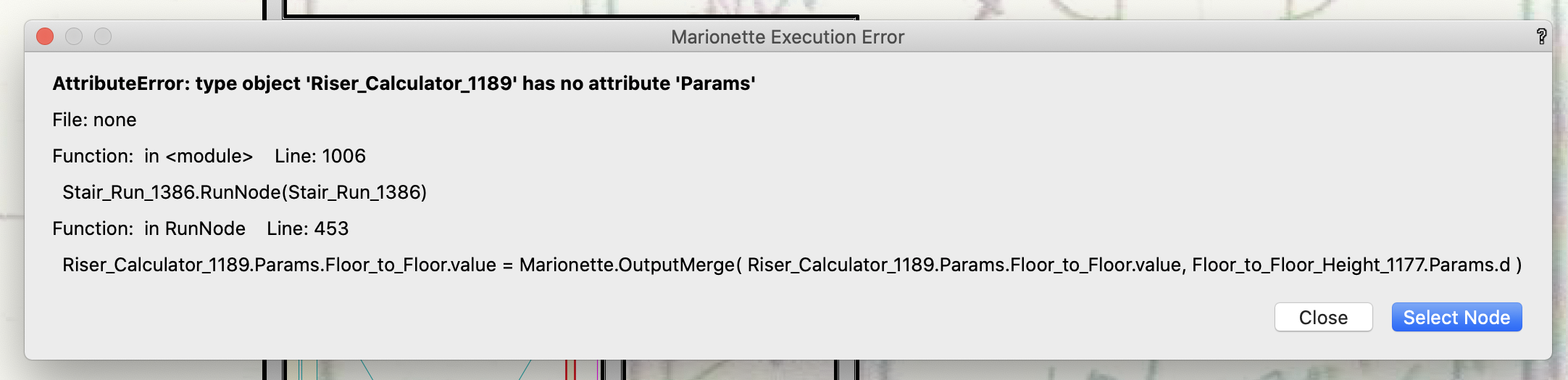
My Marionette "Stair Run" object has been working fine for a year or two or three. Welcome to Vectorworks 2021. I placed the object into a very new VW file, created in VW 2021, from a brand new VW 2021 template and... it failed. See attached. I'm an ever-increasingly unhappy Vectorworks user. All the time I've invested in Vectorworks and Marionette seems to be going to waste. *Sigh* VWIS209 (In a brand new blank VW file, at least I don't get that warning. But, even with all classes on, the Marionette object is entirely invisible. I only know it's there if I do a "Select All." Then it's in the OIP. But most of its fields are missing. It's a downward spiral.)