Itchy
-
Posts
296 -
Joined
-
Last visited
Content Type
Profiles
Forums
Events
Articles
Marionette
Store
Everything posted by Itchy
-
I have just started using VW 2024 on a few jobs and this is rather frustrating...
-
Rather old post (17 years) but I would still like this. I want the data shown for some viewports and others just the property line. I tried to see if the data tag could pull the data of each line segment but no luck on that. My workaround is to ungroup the property line, which is fine unless I need to go back and change boundaries (new subdivisions etc)
-
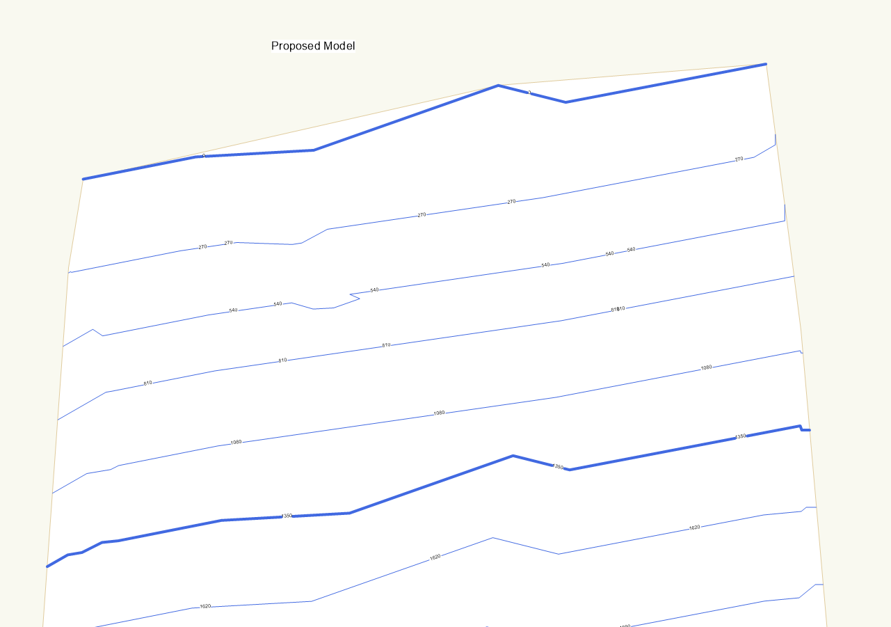
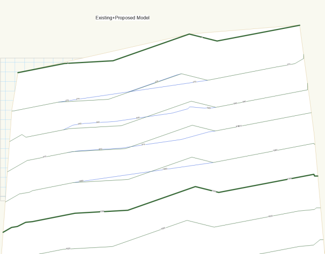
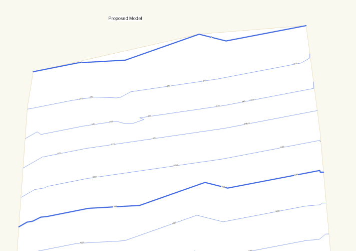
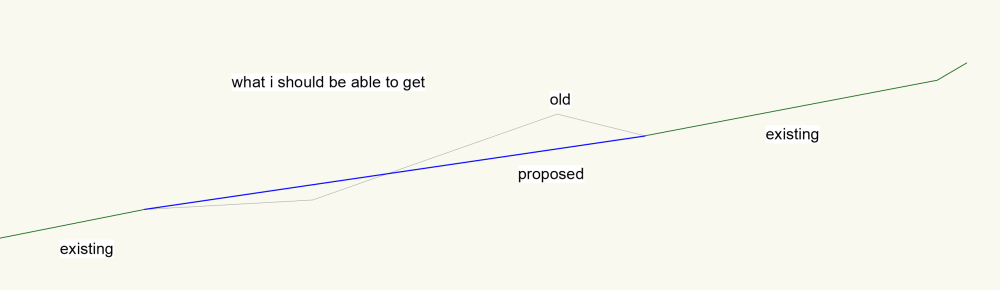
Site Model: Proposed + Existing Contours
Itchy replied to Dillon's topic in Wishes Granted / Issues Resolved
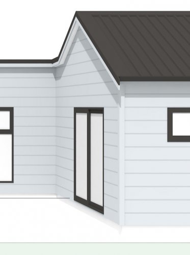
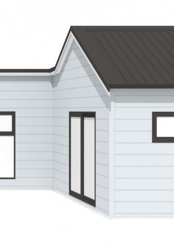
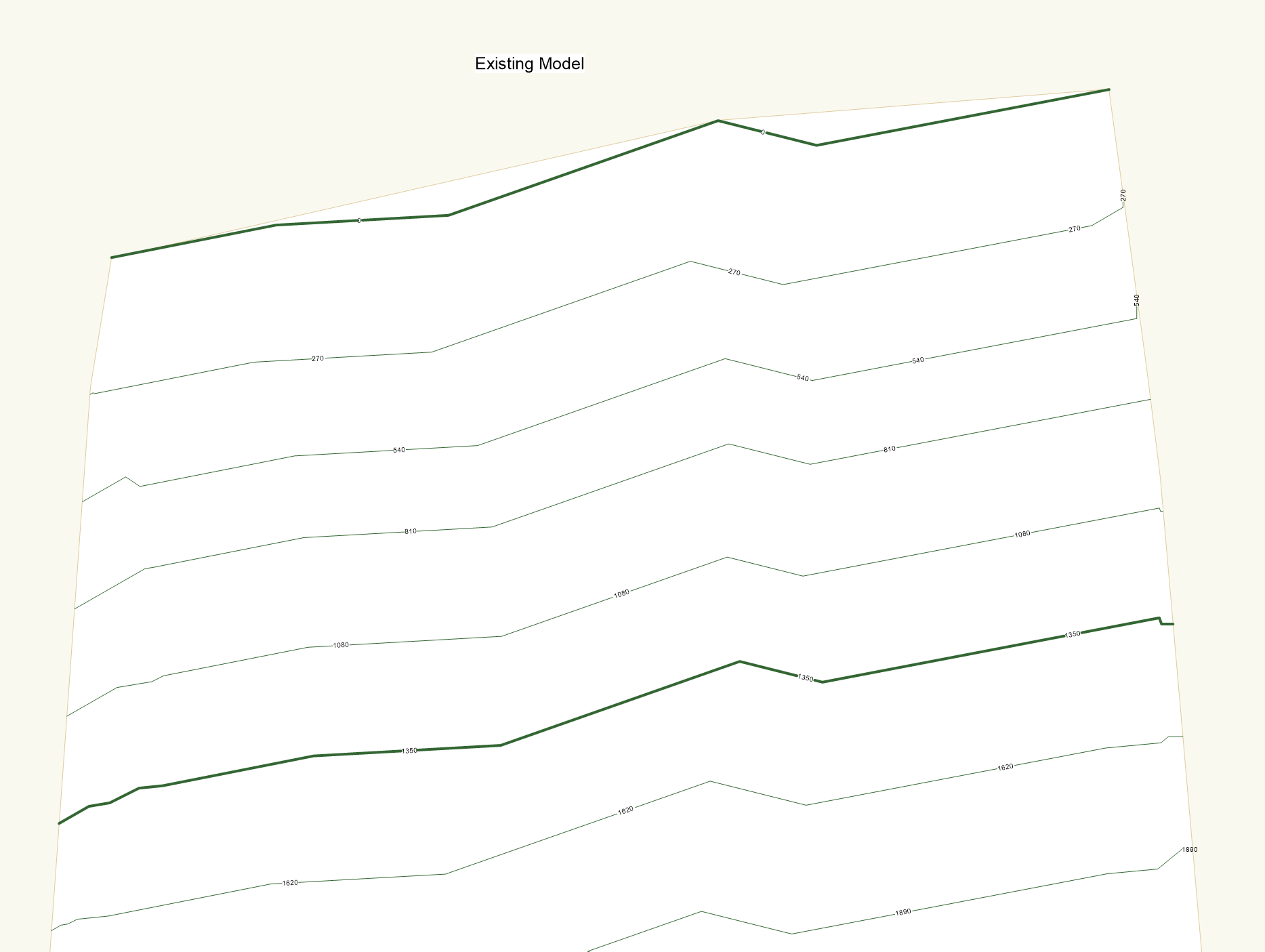
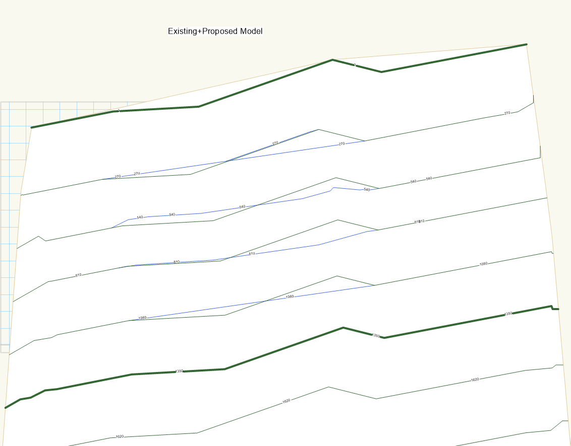
Just tried this in 2023 and issue is still there. If something has been fixed maybe my issue is slightly different to the original. But when the site model is set to proposed, you would think that any existing contours should be classed as such, and only the new contours coloured as proposed? On the existing+proposed you can see where the changes are, but graphically the existing and the existing lines that are changed are the same so not much use there. On the proposed everything is blue, so graphically on a site plan this is a waste of time, and I have to have multiple site plans set up and adjusts crops to get it to look right.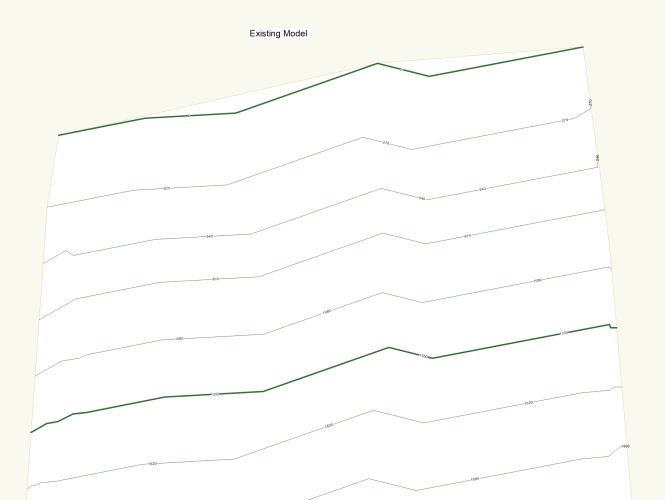
-
I use to have a VP per sheet layer and my drawing labels on the DL. I know have a VP per detail and the drawing label in the VP to take advantage of the auto coordination. Makes it simple if you must change order of things after cross referencing has been linked up. Easy to reference also as you can search in the drop down when selecting the VP to link. A few extra steps with creating the extra VPs but the auto coordination outweighs this. Also, once the pdf set has been made, you can click on the reference and it takes you through to the detail page.
-
What is the plan going forward with the native door & window tools. Will we see updates with services packs, or do we need to wait for a full release? I have been playing around with the window tool, and have managed to get it to work in both 3D and 2D to suit my needs. Then trying to copy those same settings over to the door tool though and you can't copy between the two, and there are simple differences between the two (not able to have the architrave under sill/stool in the door) that mean I can't get it to look the same as the window, and will have to revert back to WinDoor again. My hopes were built up with the window, and then came crashing down with the door...
-
Window tool - question about offset sash
Itchy replied to Mitchell (the other one)'s topic in General Discussion
Same in 2022, can't seem to figure this out. -
STRUCTURAL MEMBERS - can't be moved/glued to the place
Itchy replied to drelARCH's question in Troubleshooting
Experiencing this in both Vectorworks 2021 & 2022 -
@Matt Panzer, Is there anyway to get this to work with the detail level? I want high level detail for my renders & 3D models, but when doing sections it needs to basic otherwise it grinds the process to a halt. Everything looks so much better in 3Ds when modeled correctly, but need to swap to suit the situation. My option at the moment is to have two symbols and swap between them, one with the detail, and the other with just a loci. I can't seem to find another way around it to get the best of both worlds. Similar issue with roof cladding, using framing members with a custom symbol, but need to be able to use the detail level but it doesn't seem to work? Or do i just need two objects, the detailed roof object, and then the simple roof face?
-
VW2022 - It looks like it may be live.....
Itchy replied to Kevin McAllister's topic in General Discussion
you can also see the videos if you change 21 to 22 on the Vectorworks main page. https://www.vectorworks.net/en-GB/2022 -
Site Model: Proposed + Existing Contours
Itchy replied to Dillon's topic in Wishes Granted / Issues Resolved
Running into this now, 3 years later... -
Thanks @Matt Panzer this is great. I have been using framing & structural members with a custom profile to create vertical & horizontal siding... This will speed up the time greatly and means I don't need to cut around windows.
-
Same issue persistent in 2021. Text style fill & text color won't override class settings.
-
thanks @rDesign, while I was messing around, I also made the splash screen the same color as the icon. Not sure why they have stuck with black icon and a lime green splash screen for the last few versions.
-
You don't have a 2021 version and something compatible with windows by any chance?
-
Having this problem now, even if you set the class object to have a fill, it doesn't take the style color at all? I would have thought that the text styling should override object settings. Otherwise it makes the background color selection in text styling useless with call outs? It works with standard text (by automatically changing the object fill settings) but not with call outs, so either a bug or an oversight? Might be fixed in 2021, waiting for the localized version so I haven't been able to test.
-
Not sure if you are still around @Assembly, but did you develop this any further by any chance?
-
Thanks @rDesign that has done the trick and will suffice. Just now need a BIM piping tool...
-
Any work around to get a dashed line onto a 3D polygon so I can have my 3D pipe run and still keep my 2D plan without needing to maintain a separate 2D and a 3D object? Structural Member - Can get the view to look as I want and for the most part easy to overlay on my existing 3D polygons at the right height, bit that is super frustrating is that they keep trying to auto join and placing the risers/drops is a nightmare. Framing member, no way to draw in 3D between two loci, which means having to guess/calculate the pitch/falls of the pipework rather than just inputting start & finish (as the structural member) Piping run - only 2D Any other tools that might do the job that I am missing? I think to get it as I need, I will need to EAP to get the 3D shape, and then draw a 2D line over, either symbol or have a 2D & a 3D class
-
Problem is that the drawing name text width also changes, so if it is too short or too long, then it looks odd. I think I'll just have to set up two styles, single digit and double digit. Thanks.
-
I have three text blocks in a title block; Drawing Number, Spacer, Drawing Title I have it set up so it looks good if the drawing number is a single digit, but if it goes to two digits the number is to close to the spacer text. I thought i could set it up so that I could constrain the dimensions between the number, spacer and title, so that spacing was consistent if a single or double digit. But it doesn't seem to work. I can apply the constraint but when I edit the text so the width is bigger, it doesn't move the space and title over, the dimension changes but shows the original number? Should it be working or am I using it wrong? This is in 2019 SP6
-
I'm wanting to use this to draw my lintels as I can have start and end offset for the bearing but have the selection points set to the actual opening which is good. But there doesn't seem to be anywhere on the OIP that indicates the length of the beam? So I'm either have to then measure it to check the length so I can size the lintel. Framing Member I can easily see the span & length, and also easily modify the width x height but to show the overall size correctly on the plans I have to add 90mm to the length then move it 45mm so it stays centred. Has this tool seen any love with 2020 or is it still caught in the middle with a bunch of improvements but not quite there yet?
-
Is it possible to link text to drawing numbers?
Itchy replied to Christiaan's topic in General Discussion
Try the Detail-Callout Marker tool, assuming you can edit the marker symbols you should be able to get that to work. Just draw a small box then delete two of the points and it should leave you with just a line. http://app-help.vectorworks.net/2019/eng/index.htm#t=VW2019_Guide%2FViewports1%2FDetail_Callouts_and_Detail-Callout_Markers.htm%23CSH_32 -
Is it possible to link text to drawing numbers?
Itchy replied to Christiaan's topic in General Discussion
Now it would be nice if the secton line marker could also link to a drawing label, and that drawing label acted like the title block 🙂 -
Is it possible to link text to drawing numbers?
Itchy replied to Christiaan's topic in General Discussion
You could maybe use a worksheet with just one cell set to pull the info from the title block, you would just need to make sure the identifier that you use isn't the drawing number as that would defeat the purpose.- 15 replies
-
- 2
-

-
- automatic drawing
- coordination
- (and 1 more)
-
I have my walls set up with a horizontal line texture, all the walls are set so so that world Z is the origin and the texture lines up correctly with the other walls and all looks good. I then though set up a viewport and the texture seems to have moved up 50mm for some reason. Is there a setting I am missing or is this a bug? Thanks