


CipesDesign
-
Posts
5,153 -
Joined
-
Last visited
Content Type
Profiles
Forums
Events
Articles
Marionette
Store
Everything posted by CipesDesign
-
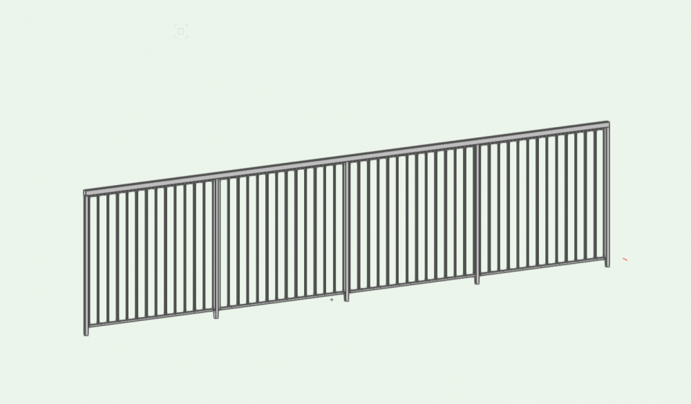
See attached. Took less than 3 minutes with Fence/Railing Plug In. I also attached the VW file... 6 ft fence.vwx
-
Hmm. Interesting. Might have to do with light passing through or reflecting off some green object(s)? Just out of curiosity, if you have Renderworks try rendering in the Renderworks Style "Realistic Exterior Final" and see if the result is any different. (Note this RW Style may take a bit of time to complete the render). If you want to post your file, I or someone can have a look...
-
Although the interface is a bit clunky, I have always been able to get what I want from the PIO. Perhaps you can post a sketch of what you're after so I (or someone) can try to create it?
-
When I hire a surveyor (often!) I always have them locate the house corners on the survey. Then I use their survey (imported .dwg file) as a base for my drawings. I always leave their work by itself in one discreet design layer and then create additional design layers for my work as needed. PS: "The only stupid question is the one that was never asked" - my primary school teacher.
-
VW 2020 Number stamp removed from legacy workspace options
CipesDesign replied to DuncB's topic in General Discussion
Number Stamp is present in Legacy tools for me. Maybe try selecting "All Tools" and search alphabetically? -
When you select the Prop Line Object a small reshape handle appears at each label location. Drag the handle and the label will move with it.
-
Unfortunately there is only a workaround. But the good news is that for this basic, rectangular, shed roof the workaround is easy. Model it. 1) Change the thickness of your existing Roof Face to match the thickness of the roof sheathing, then move it up so that its top is at the correct height. 2) Go to a side view and draw (probably in Screen Plane or Screen Plane Aligned) the rotated rectangle that would be the section of a rafter. FWIW I would normally use a standard lumber size for this, as in real life (eg: 2 x 12, or specific Glulam size) 3) Still in side view, Extrude the rectangle (this can either be a 1.5" extrusion which will be duplicated to represent each rafter, or a full-width extrusion, and it can be adjusted later so no worries) 4) Go to Top/Plan View and carefully move the Extrusion into its proper X (or Y) location. 5) You might ned to model the color bands that show on your attachment. The same (or similar) method can be used. NOTE: I almost always do this procedure as it then allows me to generate roof framing plan, etc. Make sure to create and use discreet Classes for different roof elements (eg: Rafters; Sheathing; etc.) so that you can control visibility for various views. NOTE 2: For many reasons it is helpful to create a 2d/3d Symbol for the basic rafter. 1) Go to Top Plan and move the Extrusion (some precise distance) from the building so that you can work on it without accidentally selecting other objects, 2) In Top/Plan View, draw a Rectangle which exactly coincides with the Extrusion, 3) Select both the Extrusion and the Rectangle (by dragging the cursor around both objects - see 1, above), 4) Use Command Modify>Create Symbol, and follow the naming prompts, etc. 5) Move the newly created Hybrid Symbol back its location. Now you can use Duplicate Array to frame the whole roof, and you already have the sheathing. NOTE 3: This whole thing might be possible using Framing Members, but I'm old school 😉 . I find this procedure more precise and less time consuming than fussing with a bunch of Plug-in parameters. Don't get me wrong, the Framing Member is a very useful tool, but when it comes to roof framing this is my preferred method.
-
From the Resource Manager, grab and Drag any Symbol right into your drawing... Once it's in there you can move it around, etc.
-
Sloping Fence / Different Height Poles
CipesDesign replied to GeorgeWL's question in Troubleshooting
I can think of one way: use a separate object for the chain link mesh. With your posts and rails already in place, go to a straight frontal view and draw the shape of the wire mesh. Extrude that shape with a extruded depth/height of about 1/2". Go to Top/Plan View and drag/move the extrusion so that it centers with the posts. Apply a Chain Link texture to the extrusion. Done. I have attached a file with a pretty good Chain Link Texture (in two file formats: 2019; 2020). I can't remember where I got it, but it was someone through this forum, a long time ago (thanks!). Chain Link Texture! v2020.vwx Chain Link Texture! v2019.vwx -
Rob, Sure you can post/attach the file here. I'll be happy to have a quick look. (So many settings, nothing is simple anymore!). P
-
Try using View>Create Section Viewport. {VW's Help, which I just checked, would be worse than useless for a noobe, as it is assumes that the user already knows the following basic functionality}: 1) Go to Top/Plan View 2) Select Menu Command: View>Create Section Viewport, then immediately (as in very next mouse click) 3) Draw Section Line (like all lines and other shapes, you can constrain horizontal or vertical by hold Shift Key while drawing), then immediately 4) Double Click to choose direction of view (Notice the little triangle (arrow) pointing to one side of the Section Line. You can switch sides by moving mouse, then double click) 5) Assuming you've got all that, a Dialog will appear ("Create Section Viewport"). Choose On Sheet Layer (or New Sheet Layer) then choose other parameters (note: all of these except the Viewport type can be modified later, so don't fret too much). 6) Click OK. Vectorworks will take to to the designated Sheet Layer and you will see the new Section Viewport. I hope that helps get you started.
-
You can modify your Workspace via the menu: Tools>Workspaces.
-
Importing: File>Import>Import PDF. Best to do this into a clean (empty) Design Layer which is set to the same scale as the Design Layer in which you will create the trace (eg: for me, all floor plans are generally drawn/modeled in 1/4" = 1' scale). Also, make sure the "Snap To Geometry" option is ON (note: this will only be useful if the PDF was created in a program that has certain types of geometry; tends to work with most PDF's generated from CAD programs; tends not to work with hand-drawn/scanned documents). Scaling: Once the PDF has been imported, use the line tool (or measuring tape) to check that the scale is correct. If the snapping is functional (see above) then you can very accurately measure any known distance. If the scale is correct, then proceed to trace (see below). If the scale is incorrect, use the command "Modify>Scale Objects " to correct the scale, then proceed to trace. Sometimes there is a bit of trial and error to get the scale correct. Undo can be your friend here; and /or symmetric scaling by very small ratios (1.05, or .99 eg). Tracing: If snapping is functional tracing is pretty easy. I usually trace (using Wall tool, or just lines or rectangles first) right in the PDF Design Layer, then move (or copy and paste in place) to another discreet layer. I do this because even though I wan to keep the PDF for reference, it can really slow down basic functions (screen redraw, eg). So being able to make the PDF invisible is helpful going forward in order to avoid these sorts of lags. Hope that helps.
-
I'm not entirely sure, but I would guess that the crossed planes which make up the props are not playing well with Twin Motion's rendering. If it was me I would try using the trees and plants provided in Twin Motion, and only use building models exported from Vw's. FWIW, in my limited messing around with TM I noticed that the trees in TM will pick up on seasonal/weather and wind changes built into the program (which are super cool!!) and I would bet that imported trees will not behave like that. Just a thought.
-
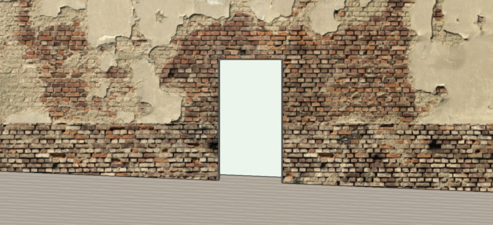
You can accomplish this visually by simply lowering the door. As long as the Floor (stage) is continuous, as continues past the wall, it will look as intended. See attached example:
-
I have used Floor Objects for countertops for a long time. They are easy to manage and easy cut holes into using "Clip Surface". As a note I use an additional Floor Object for the backsplash if that level of detail is needed. Remember that any Object can be placed in any Class in order to control Attributes and/or Visibility.
-
I assume you have seen (and followed) this: http://app-help.vectorworks.net/2020/eng/index.htm#t=VW2020_Guide%2FCameraViews%2FCreating_an_orbit_animation.htm&rhsearch=animation&rhhlterm=animation&rhsyns= But just in case. FWIW, my method (above ) is not really a workaround, it is just the way the procedure is (re) designed in VW's 2020.
-
There are actually 2 (two! wow that's some bad UI design) Height Fields in the OIP for a Door. The one nearest the top of the list controls the Height relative to Layer Z; the one further down (just above Width) controls the size (height) of the door. I hope that helps.
-
This may not help, but since garage slabs generally slope I always use a Roof Face instead of a Floor or Slab. I then set the wall in which the overhead door/s is/are to Bottom Offset = -6" (eg), and lower the doors by the same amount. This works for me because I do not use Stories, and do not bind any objects to any other objects (in other words, no BIM for me).
-
For a simple project you can just control the wall height by inputting the desired height into the Object Info Palette, either in the "Height" or the "Top Offset" fields (these should be the same as long as the bottom of the wall(s) is/are at Z=0.
-
The process for Orbit Animation has been modified for 2020. (I also had a hard time with it at first). It used to be that I would create an object in the desired center of rotation, then set the animation to orbit around that object. Now, in 2020, I do this: start out with a RW Camera View at the desired distance, height and perspective; Select the entire floor (or create a 3d object that covers the entire floor area you wish to view) then go to Model>Create Animation>Create Orbit Path. In the next dialog choose 360º and Around Selection. Give it a minute or so and you'll see that a new object has been created (an "Animation Path"). It's a Camera attached to a path (nurbs object I think). When you choose Play from the preview options you will notice the camera moves around the path (like a drone shot or dolly shot, sort of) but that the view does not change (FWIW, this part is bad programming as it doesn't really give you a preview). In order to actually see the result, run a short and low frame rate animation. Although there are some odd things in the new process, the cool thing is that you can actually select the Animation Path object and move it up/down; add vertices to it to make it conform to a user chosen path; etc. Once you get an acceptable result in a lo-res, low frame rate sample, then you can create a higher res version... I think I got it all in the explanation, but let me know if there are followup questions. P OH PS, to the Original Question: try using a perspective instead of an orthogonal view. You can move the camera (Animation Path ) up and change the angle of view.
-
Note: Perhaps this is beyond the scope of what the OP asked, but... (also see below*) This is a really tricky problem in VWs. There are many ways to fake it, for renderings and visual presentation, but I have never found a way to create an anatomically correct road (with curvature, camber, drainage, etc), or other such object. Even though you can create a Road which accurately follows user-defined slope parameters on a Site Model, the Road will be flat in section, which is obviously an over-simplified result. I have to accept that this is the limit of what we can do with VWs, therefore my solutions are usually two-fold in order to serve the two general results I am after. First, I need to show the client(s) a pretty picture which is more or less accurate; second I need to show a (road) builder exactly how to build it. The first can be accomplished by using the Road tools (for complex roads I like Nurbs Roadway for this, for simpler items like Pathways or Driveways often the Roof Face object can be used, sometimes in combination with Floors, etc.) with textures for paving, etc. Sometimes Walls are added where they will needed in real life. Sometimes cars, people, trees are added depending on what my goal is. When done using an accurate (survey based) Site Model, this approach gives me two important results: it generates the visual for the client, and it gives me the basic locational, elevational and curve data for the builder. What it lacks is the ability to generate an accurate Road Section (Profile). This can be done fairly easily in two ways: one, just draw the profile as we used to in the "old days". Two, cut a Section through the road and draw the road profile in Annotations. Both entail pretty much the same thing. Not a terrible compromise in my opinion. Hopefully that gives you some ideas! *If a driveway is your goal, try a Roof Face object. It's the simplest method I have found (with all the above caveats included).
-
Late to the party here... One observation: when opening the "unwanted holes in walls sample file" (the first one posted, above) in VW's 2020 I notice two things. First, the "updating walls" portion of the file translation takes a long time; second, when the file finally opens, there are no unwanted holes. P
-
The standard way to do this would probably be in Hidden Line, and with various different views (Plan; Front; Side; Section(s)) to show design intent. If you need to hide the shading on the curve (in the front view you posted) you could just draw over it in Annotations.
-
Merging walls with extrusions???
CipesDesign replied to AngeliqueRoggeveen's question in Troubleshooting
Try using the Fit Walls To Object command. 1) create the rounded geometry as a 3d object, making sure that the object completely covers/overlaps the Walls. Put this new object on a new Design Layer (different form the Walls). 2) Select the Wall(s) to be reshaped, then choose the Fit Walls to Objects command; select the new Design Layer as the "Fit To" Layer. This should result in the Walls following the contour of the rounded object, although as a note, the curves on the Walls will actually be a series of segmented flats (not a true curve).


