ThreeDot
-
Posts
167 -
Joined
-
Last visited
Content Type
Profiles
Forums
Events
Articles
Marionette
Store
Everything posted by ThreeDot
-
Fine Tune Camera View - Wait for User
ThreeDot replied to Kevin McAllister's question in Wishlist - Feature and Content Requests
OMG, yes! -
Ditto. We are having the same problem in our office.
-
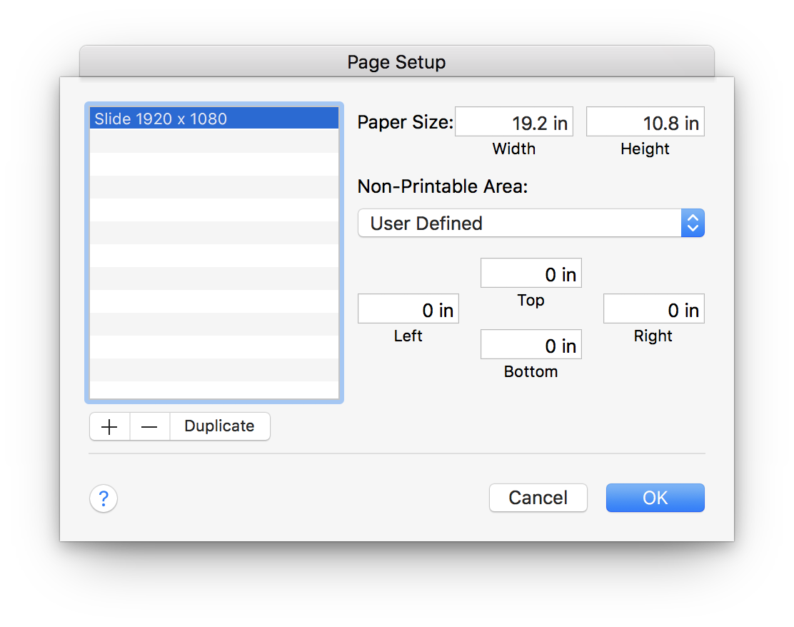
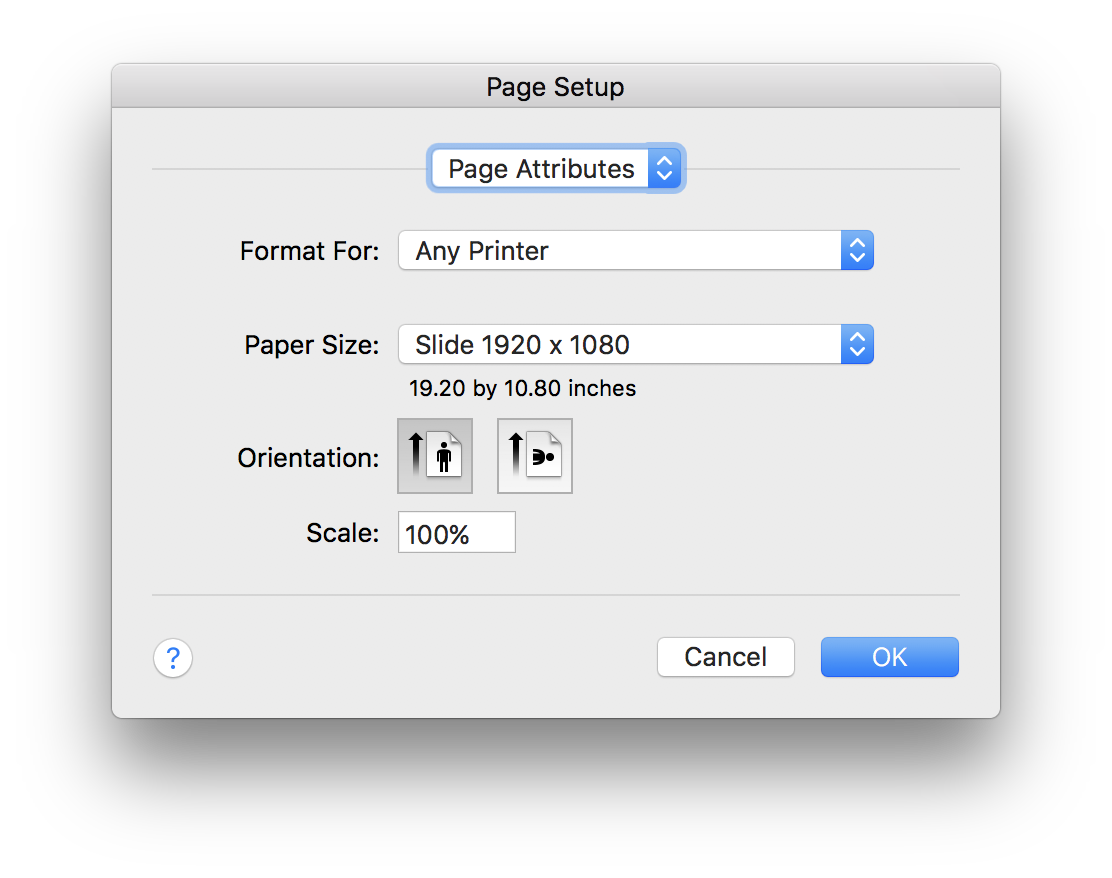
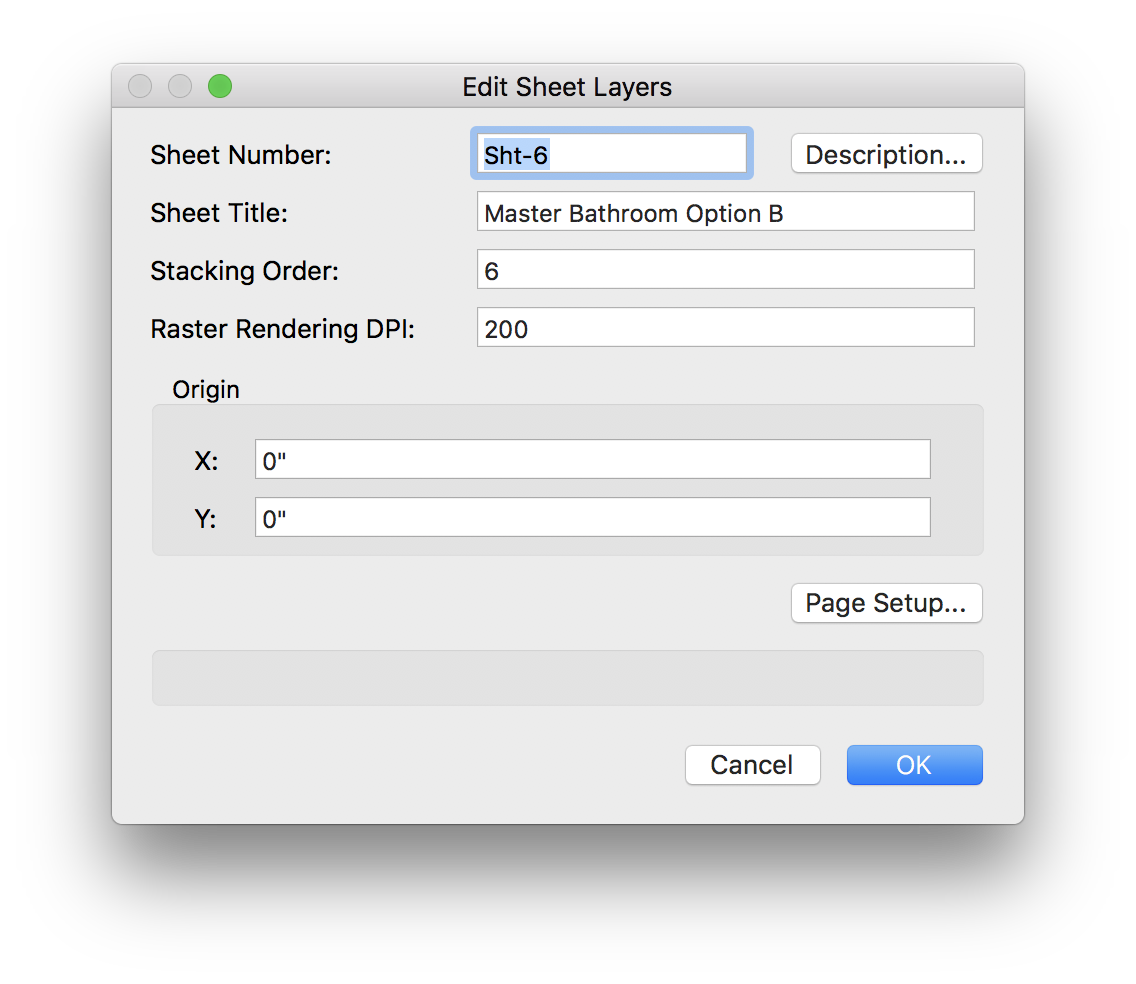
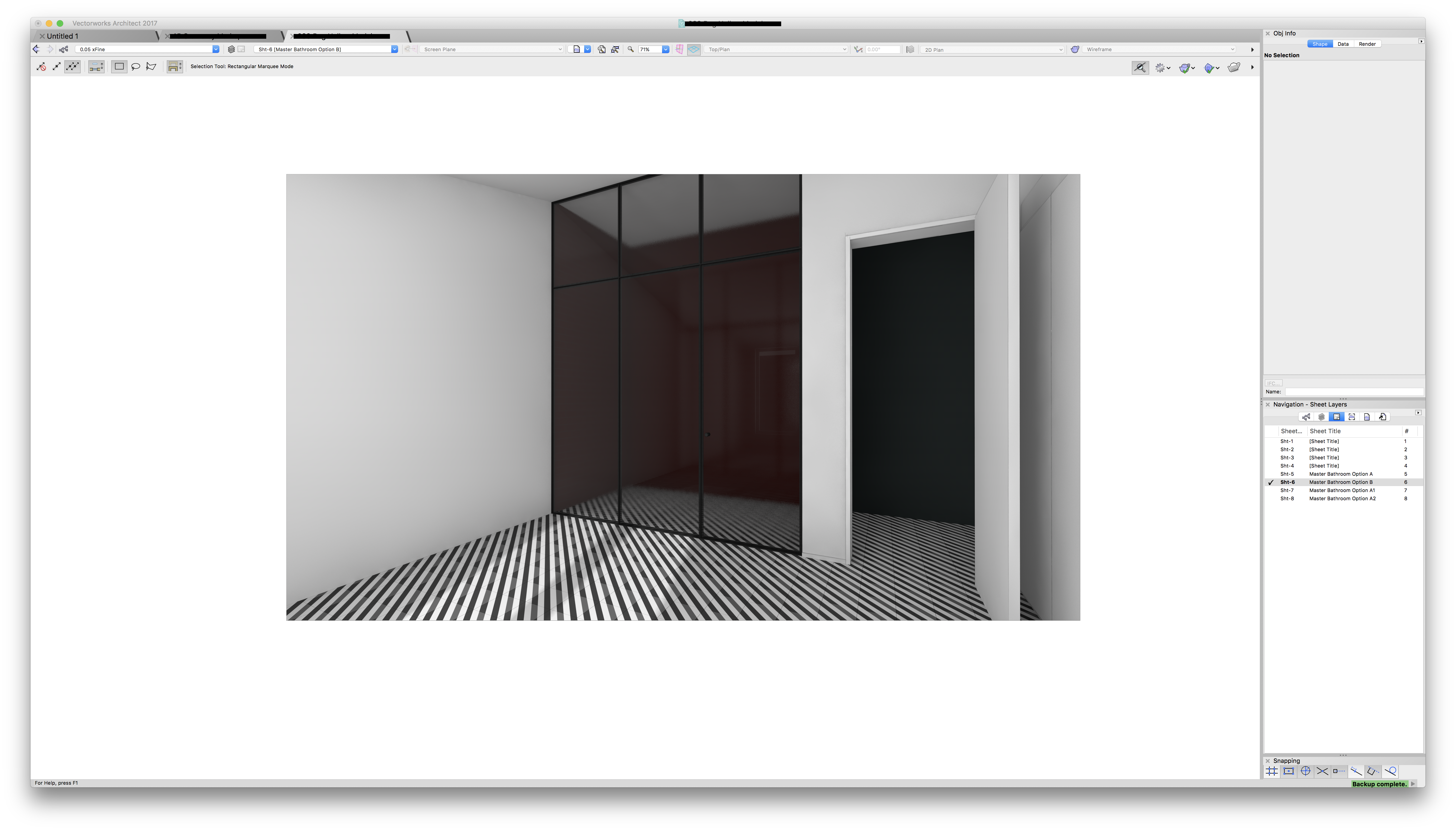
I've been struggling with this as well, and have come up with the following workflow. 1. Create a custom page size in the macOS page dialog. Set paper to 19.20" x 10.80". You can use any imperial or metric page size. The physical size is not important. This is just a 16:9 ratio and with round numbers and a tidy multiplier. I tend to drop images into Keynote to present to clients, and 16:9 images work perfectly. 2. Create a sheet layer and select this custom 16:9 page size. If I set the sheet resolution to 100dpi, the result is a 1920 x 1080 (2K) image. If I set resolution to 200dpi, the result is 3840 x 2160 (4K) image. 3. Create a new camera on a design layer and link it to a viewport on a sheet layer. I set the camera quickly to approximate the view I want. I don't fuss with the camera on the design layer, because I'll fine tune it later via the sheet layer viewport. 4. On the sheet layer, fit the camera crop exactly to the 19.20" x 10.80" page boundary. 5. Double click viewport, select "Edit Camera", and fine tune the view. Click "Match Current View" before existing the viewport and returning to the sheet layer. 6. Render the image. 7. To export final render, (a) select "Export Image File...", (b) set export area to "Each Page as Separate Image", (c) set resolution to 100dpi or 200dpi, to get a 2K or 4K image, (d) confirm that pixel dimensions correspond to the preferred output resolution, in this case 1920 x 1080 or 3840 x 2160, (e) select format as PNG, JPG, or whatever, (f) and click Save. The result is a perfect 2K or 4K image. You can save individual images as described above, or batch process using the Publish command.


-
Hello, I'm looking for paid consulting help and not sure the best place to post. Sorry if this is incorrect. I've been a Vectorworks user since 2001, starting with MiniCAD then moving to Vectorworks. I also worked in an AutoCAD office for many years before returning to Vectorworks in my own practice. Until recently, I used Vectorworks exclusively for 2D drafting. 3D modeling was done in FormZ, Rhino, and SketchUp. I've recently been transitioning 3D modeling to Vectorworks for a more streamlined workflow, but after many years in my own small practice I can't help but wonder if I'm using Vectorworks efficiently. Software and industry best practice have changed a lot over the years, and it would be helpful to have some outside perspective. I'm looking for a local (New York City) or remote consultant with a wide breadth of experience and similar OCD tendencies to review my workflow and make suggestions about how to improve. Depending on who is interested, I'm also looking for help drawing and modeling active projects. PM me for details. Best regards, Matthew
-
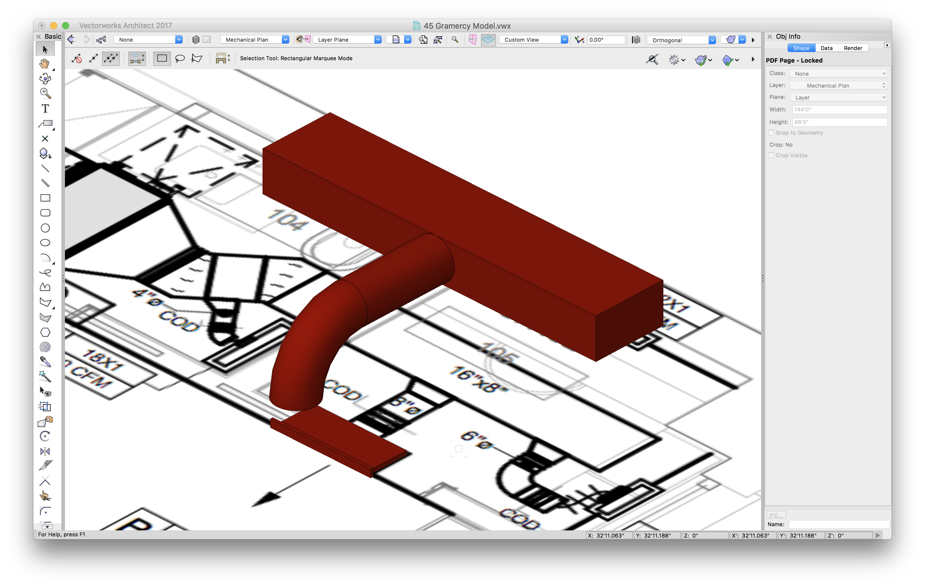
I'm working on an apartment renovation in an old building, and we are inserting a new split ductless HVAC system. It's a relatively small system, but it must be coordinated very carefully with existing structural and new architectural elements. I decided that I should add HVAC parts to my model. I've never used the HVAC tools, and I appalled at how bad they are! Each duct is placed one-by-one, which is fine, except that nothing snaps to anything else and there is zero intelligence about how parts connect to each other. I see very little documentation in the help manual and limited discussion in the forum. Does anyone here use these tools for actual work or are they completely pointless?

-
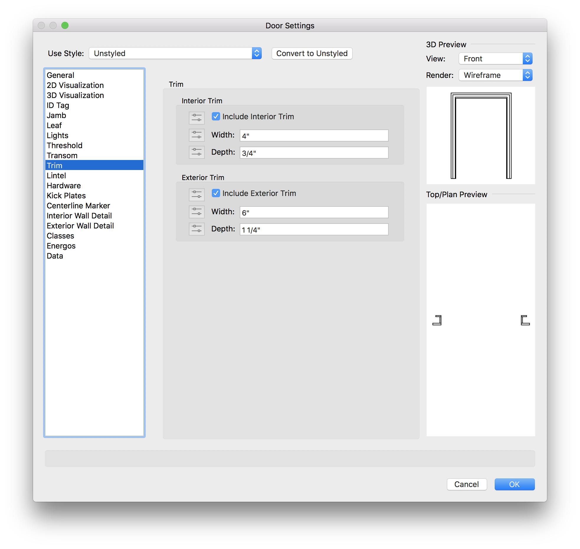
Is there a way to assign casings to door and window objects? I can't imagine that drawing paths and extruding profiles for each opening is the recommended method, but I don't see a way to attach a polyline symbol in door and window settings. Similar question for base moldings. I see a Marionette method for crown moldings in the forum, but I'm having trouble getting that to work. I will try again if that is the current best practice.

-
That sort of works, but the extruded edges get a bit funky in my sample. I'll play with it more. Thanks for the idea.
-
I reduced the material thickness and adjusted the camera view to reduce this effect. Thanks for your help!
-
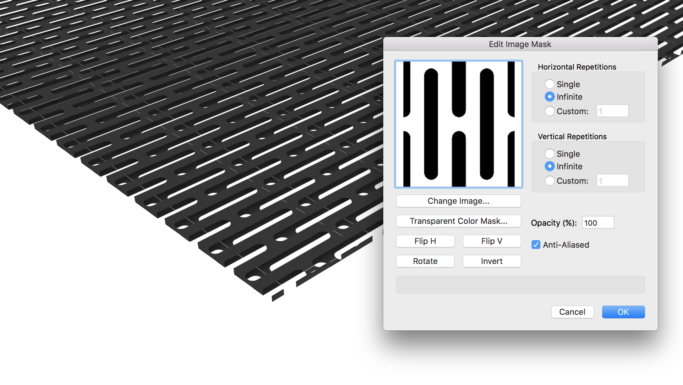
I applied an image mask to a box so that I can represent a perforated steel plate. The PNG image has an alpha channel, and it renders correctly. However, when applied to a solid box, the texture maps to the top, bottom, and edges and the result look like a perforated hollow box rather than a perforated plate. Is there a better way to represent a perforated metal plate?

-
Is it possible to render a tile pattern created with the 2D editor? It shows up just fine in the top/plan view but it does not display or render in 3D views.
-
Multi-key shortcuts
ThreeDot replied to VincentCuclair's question in Wishlist - Feature and Content Requests
I cannot not agree more! Shortcuts need to be overhauled. Even after years of use, your stupid shortcuts are killing me. The current system is bizarrely antiquated and convoluted. Many of the shortcuts are still based on the toolbar layout from MiniCAD, rotated 90?, and mapped onto the lower-left corner of the keyboard. Really? Who thought that was a good idea? Furthermore, later versions of Vectorworks changed the default toolbar layout. What little sense this nomenclature may have made 15 years ago make no sense at all now. AutoCAD, Rhino, etc. have all moved to a start-typing popup box. For example: User types: "M", "MO", "MOV", or "MOVE" and hits Return to activate the move tool. This is a frequently used tool, so simply hitting "M" + Return would activate the tool. User types: "M", MI", "MIR", etc. and hits Return to active the mirror tool. Mirror is a lesser used command, so if a user types "M", mirror may be the second option. If a user types "Mi", it would become the first option. User can select by hitting Return. On Mac, there is an superb tool called Alfred (www.alfredapp.com) that works the same way for system-wide commands. The beauty of this shortcut method is that a user never has to remember convoluted or abstract systems of commands. It also bridges the learning gap for ex-command-line AutoCAD users. Users can quickly and easily find tools by typing relevant letters. "M" is far easier to remember than Shift + "M" and "MI" is easier to remember than "=". Another major UI no-no is the Mode Bar. It requires a user to remember the tool mode from the previous use. For example, when using the mirror tool, I never really know if the tool will mirror or mirror-copy. Every time I use the tool, I have to look at the mode bar to check status. Users are creatures of habit. It's far more intuitive for a user to hit "MI" to mirror and "MI" + Tab to mirror-copy (or "MI" + Tab + Tab for another mode). Because the keystroke it always the same, I never have to look at the Mode bar for this tool. It becomes second nature to hit "MI" + tab to mirror-copy. Time to let go of MiniCAD. It's okay, really. -
I created and inserted elevation benchmarks in my drawings weeks ago. Recently, I noticed that when I edit, copy, duplicate, or move these in anyway the linetype changes. I pruned dash styles in this file back to the original 10 -- several had been added or modified in the intervening months -- but this has had no affect on the elevation markers. How can I control / change the linetype on elevation benchmarks? Thanks.
-
I'm setting out to update and reorganize my hatch library and am looking for advice on best practice. Some questions: Do you create several scale-specific versions of the same hatch (e.g., 3/4", 1 1/2", 3", etc.) or, more generically create small, medium, large versions? Does it become cumbersome to manage this going forward or is it easier, with VW 2010, to create hatches at, say, 1" and scale them accordingly per object (0.25=1/4", 1.5=1 1/2", 3.0=3", etc.)? Do you create vertical and horizontal versions of each hatch or just rotate on a case-by-case basis in 2010. Do you create different colors/grays of each hatch? Also, has anyone else noticed that hatches with transparency don't actually print or PDF with transparency? Thanks
-
Ah, my favorite legacy frustration. 1. Base shortcuts on Minicad default, two-column tool layout, rotated, and laid graphically, in order, across the keyboard. 2. Allow user to resize tool layout (3 wide, 4 wide, etc.) 3. Allow user to add, remove, and reorganize tools and toolsets. 4. Add new tools and features. 5. User will remember Minicad default, right?
-
Ugh, I should be more careful. When you set a line to "None" it automatically defaults to "0.00" and vice versa. Nevermind. I suppose I was leading myself down a path that I've always felt odd in Vectorworks. That is -- unlike AutoCAD's defpoints -- the None class prints unless you turn it off in each viewport. I sort of wish the None class (or any class, really) could just be non-printable by default (or toggled via class settings).
-
Then it seems obvious that functionality should be: 1. Set pen to "None" if you neither want the line on screen nor printed. 2. Set lineweight to "0" if you want the line on screen (vaguely indicated as a guide or reference) but do not want it printed. Otherwise the functionality of lineweight 0 is redundant and unnecessary. Moreover, "lineweight" is an indication of how thick the line will print and does not implicitly correlate to how the line is drawn on screen -- if lineweight is 0, the line should be displayed (lightly, perhaps) but not printed. This would be a great way to handle non-printing classes and elements. The functionality of the Locus is similar in that it displays a point on screen, for reference, but does not print.
-
In that scenario, is there a difference between setting lineweight to 0 vs. setting line to "None"?
-
I've always wondered how 0 lineweight was useful anyway. It seems that the 0 lineweight should default to a visible, on-screen representation for a non-printable line, similar to the 2D locus.
-
I'm having the same problem -- the attribute and navigation palettes disappear after hiding Vectorworks.
-
Oh, please. Architects have used their eyes and brains for collision detection for millennia and suddenly it's a crisis that software can't do it for you. I should be appalled that VW can't attend site meetings for me. Off to the wish list...
-
VW 2009 and upcoming Mac OSX 10.6 Snow Leopard
ThreeDot replied to AN Design's topic in General Discussion
Actually, I do work in software development. Perhaps my comment was hastily written, but you read to much into it. I was responding to previous comments without bias or judgment against Nemetschek NA. I wouldn't expect software as complex as Vectorworks (with dual platform support, legacy code, outside vendors, multiple localizations, etc.) to be reliably compatible on day 1. Anything to the contrary would be irresponsible. Oh, nevermind. -
VW 2009 and upcoming Mac OSX 10.6 Snow Leopard
ThreeDot replied to AN Design's topic in General Discussion
Developers have been receiving Snow Leopard builds for months, including the final, or near final, build (10A432) several weeks ago, and would have a pretty good bead on any issues / problems. Discussing compatibility with an upcoming OS release is not a violation of NDA; it's a business decision. -
Special Characters
ThreeDot replied to ThreeDot's question in Wishlist - Feature and Content Requests
I can and do use shortcuts, but I can't remember all of them all of the time. Frankly, I've got better things to remember. It would just make life a little easier. -
I'm running Vectorworks on OS X. When I need a special character I switch over to Finder and select Edit>Special Characters... from the menu bar. It would be nice if Vectorworks had a direct link to the native OS character palette or its own, built-in list of architectural and engineering symbols for quick access.
-
Christiann, Thanks for the detailed explanation. logSheet does seem like the best option; the limitations are annoyances rather than killers (as in PrintCapture or Sepialine). I'm testing the trial version now.