


barnes2000
-
Posts
429 -
Joined
Content Type
Profiles
Forums
Events
Articles
Marionette
Store
Posts posted by barnes2000
-
-
Has anyone that uses this device been able to get the Touch Ring to control Zoom in Vectorworks, like you can with a scroll wheel on a mouse?
The touch ring works great in photoshop, but I can't get scroll or zoom to work in Vectorworks. -
@GuntherThirteen years ago, I posted this question. This morning, I found myself needing to create a flattened elevation, and I thought I'd google the question. The second hit to my Google search brought me back to this post. Haha.
-
 1
1
-
-
@Rob Books Is there a way yet to connect vertical or angled pipe to a truss system? The Insert Connection tool only allows top or bottom connections. I'm looking for a trick to side mount pipe to a truss system.
VE?.thumb.png.9c2b90159841d6e49ea43f3689f2522d.png)
-
 3
3
-
-
I believe this forum channel was created a few years ago, when SubD modeling was first introduced. I'm not completely sure, but my feeling is most Vectorworks users(especially those who are not familiar with other 3D modeling programs) are not comfortable with SubD modeling yet. It can be a little overwhelming, but it is extremely versatile. It will only get better as more improvements are made to it.
-
11 hours ago, Andy Broomell said:
I didn't realize you could extrude edges! Apparently it's only edges that are along an open side of the shape.
Thanks!
Yep, and I now know how to extrude more than one at a time. Select the edges or faces and then hold Alt while dragging a coordinate handle.
-
1
-
-
Yes, I am referring to Extrude Mode in Subdivision modeling. You can extrude faces and edges. I was just wondering if there was any trick to extruding multiple edges at once. Apparently there is not...yet.
Scott
-
Is it possible to extrude more than one edge at the same time? If I select more than one edge, the moment I choose the Extrude tool, they deselect.
-
Does anyone know if it's possible for a curtain wall to have the framing and panels on only one side, and the other side just be a full panel with no segments?
-
-
Does anyone know if you can texture a particular panel separately from the others in a curtain wall?
Thanks,
Scott
-
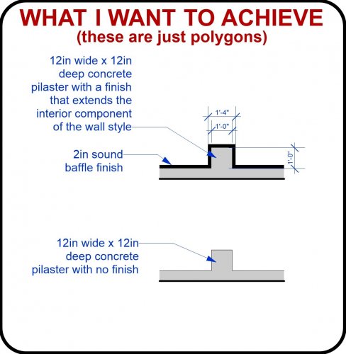
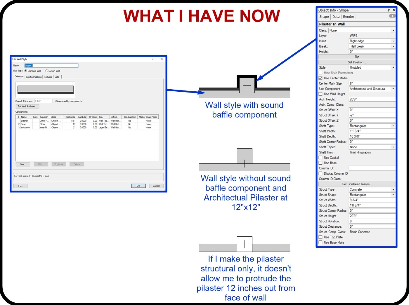
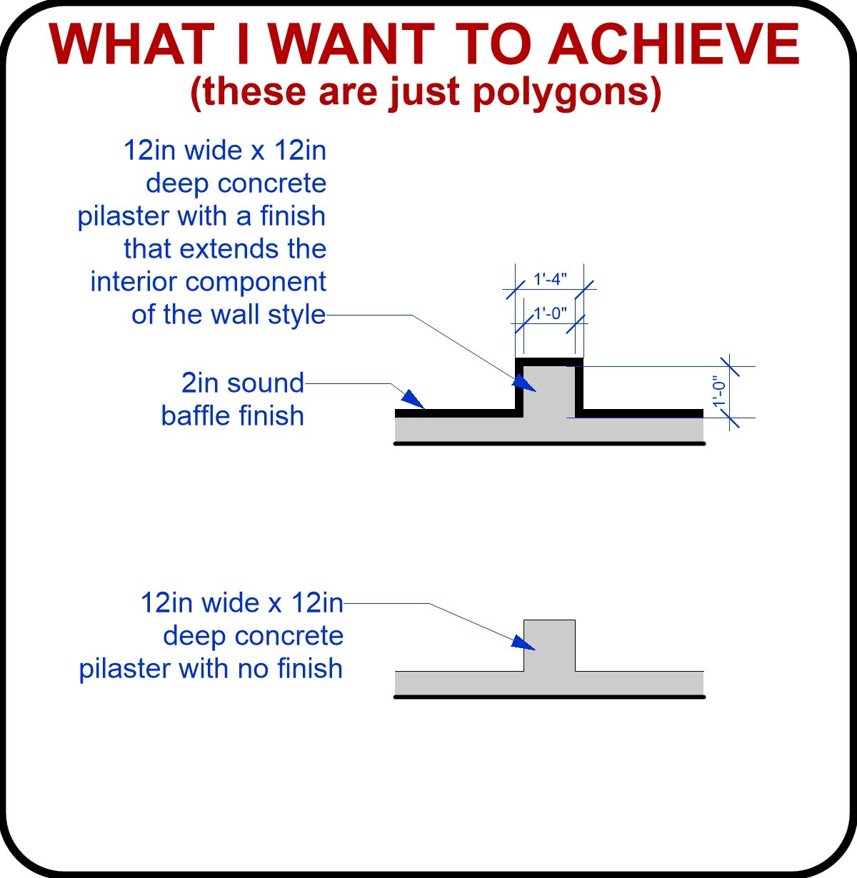
I am looking for help from my architectural friends. I am trying to redraw an existing building. It is warehouse that looks to be tilt wall. It has concrete pilasters every 24 feet. Usually, when I draw a pilaster, I always make them Architectural Only with Half Break which allows me to attach the pilaster to the interior edge of the wall and set the width and depth as needed. For the sake of just trying to properly learn how to use this tool, I am trying to figure out how to use them with Structural and Architectural settings. Maybe I am not understanding the proper way to use them, but I'm struggling with the fact that the structural part of the pilaster doesn't allow me to attach to an edge. They seem to have loci that are offset from the center, and determine the alignment of the pilaster.
Please see my attached images to see what I am talking about.
I am trying to achieve a 12 in wide X 12 inch deep structural concrete pilaster to the wall so that the exterior of the wall is unaffected, and the pilaster protrudes out from the interior of the wall 12 inches. Then, some of them would have a 2inch wider architectural exterior of the pilaster to match the wall style they are attached to. None of the tutorials I've found about pilasters, do not really talk about all the settings and various ways to place them. Thanks.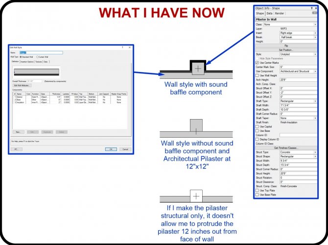
-
When I use the Radius Selection Mode of the sculpting tool to push and pull the site model surface, is there a way to anchor the 2D boundary so that the boundary edge stays at zero?
-
What is the node I should use to make input be based on the 3D object I have selected?
-
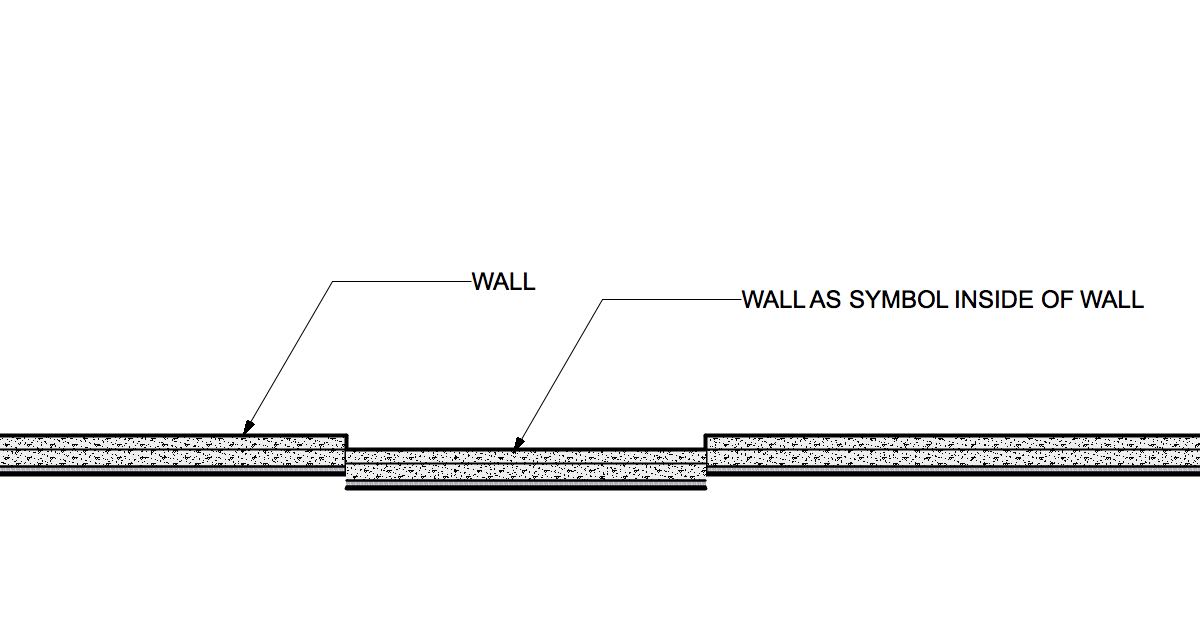
What about just making the recessed wall a symbol and dropping into the actual wall? You could still make a new Wall Style for the recessed wall to help the Top/Plan view. I was a little lazy in this example. The inserted wall should be thinner so as to flush on the back part of the wall. The nice thing here is you can still adjust the height in OIP, and/or edit the symbol if needed.

-
Are you using a 3D mouse from 3DConnexion?
-
-
Upon creating a new Project, I notice that the username for the initial administrator is grayed out and not editable. Where is the username coming from? My PC username? Windows? Vectorworks install?
I'm asking because, for whatever reason, the name is spelled wrong. -
There is a known issue with manually selected Vision symbols in the Fixture Mode field not holding.
There is a workaround, but keep in mind, it could affect other things, like Lightwright.
Currently, Fixture Mode field references the Instrument Type field. Fixture Mode should automatically be assigned based on the Instrument Type, but the problem is that the symbol names must match exactly. If the Instrument Type reads: VL3500 Wash, but the Vision Symbol reads: Vari*Lite 3500 Wash, it will leave the Fixture Mode blank. If, before you plot the symbol, you edit the Instrument Type name of the symbol to read exactly the same as the Vision Symbol, then Vectorworks will automatically fill the Fixture Mode with the matching Vision Symbol. You should even see multiple mode choices in the drop-down menu of the Fixture Mode. Once again, changing the Instrument Type name could cause issues with Lightwright, since that program references the same field.
-
1
-
-
When in doubt, use the search bar. It will locate whatever symbol you are for quicker than you could browse yourself.
-
An updated manual for Vision (They dropped the ESP) is being worked on.
Vision Symbol selection is no longer in the Edit Vision Data menu. This is only for editing things like Gobo Wheels and Color Wheels and such. The Fixture Mode field is the place to choose Vision symbols for your selected symbols.
-
Yes, symbols are now based on a default hanging orientation. I believe this is because it is the standard for Vectorworks symbols, and they have updated the libraries to work together now.
I have discovered that the Fixture Mode field is based on the Instrument Type field. If nothing is in the Instrument Type field, Fixture Mode defaults to None. There is a bug here that has been reported. In the meantime, if you edit your symbol and enter an Instrument Type that matches the Vision symbol name, you should see the Fixture Mode choices available in that field. For example, I had a modified symbol of a Sharpy, but I did not have "Clay Paky Sharpy" in the Instrument Type field of my symbol. When I tried to force the Fixture Mode to be the correct Vision symbol, it wouldn't stay. Once I edited the Instrument Type field of my symbol, the Fixture Mode was automatically updated, along with other Sharpy choices to pick from.
-
Short answer is it does not export 2D objects, only 3D geometry, and their associated textures.
Pretty sure it has to do with the API they are using for the 3D Web App. -
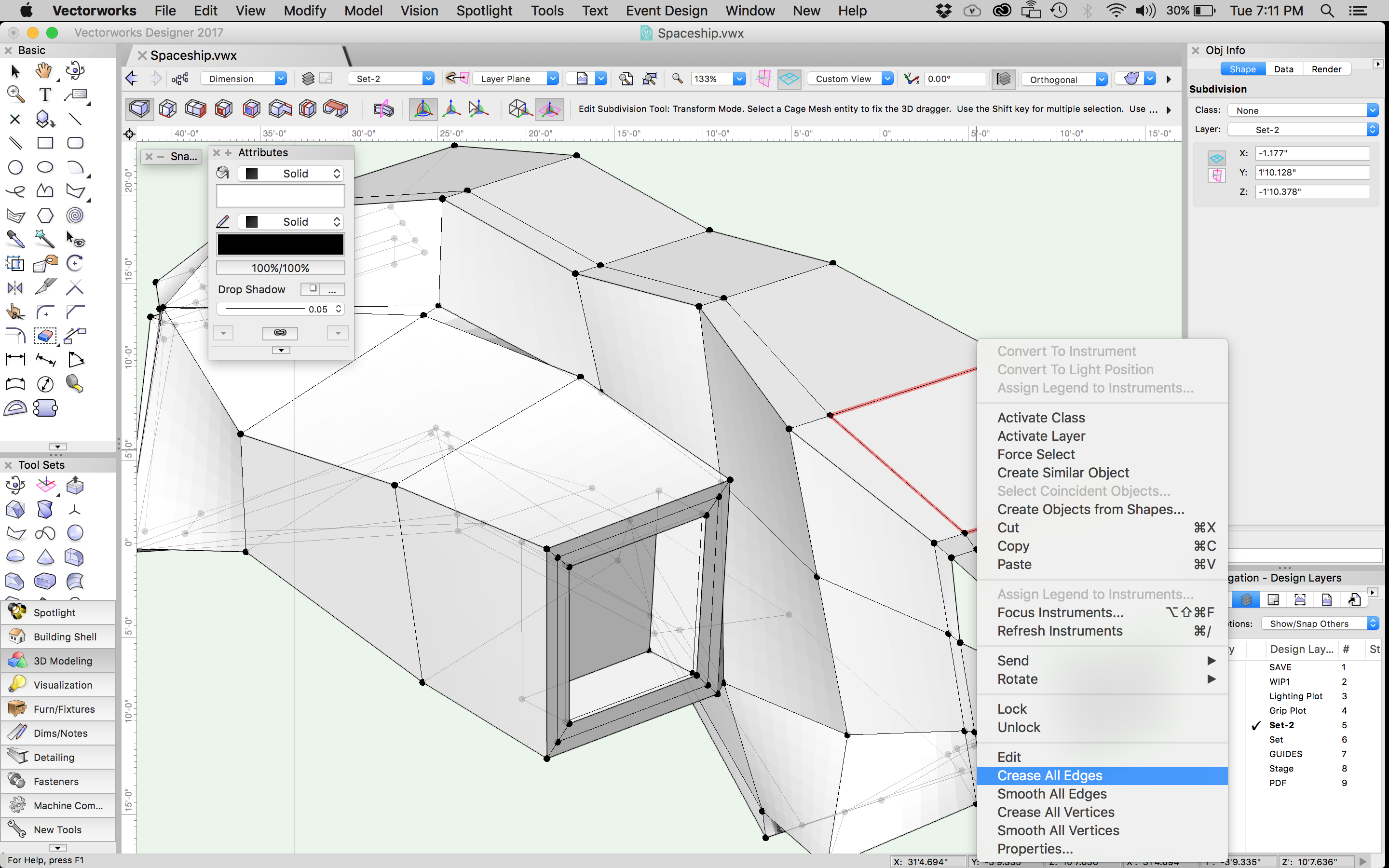
@Kaare Baekgaard, just as Jim has said, you can Crease or Smooth all the edges or vertices at once to help better see the model as you model it by right clicking on the cage anywhere.

-
1
-
-
Yes @JimW. When you want extra displays, a printer, and a subwoofer in your mobile desk, why not just make it a desktop PC? The new one I just had built is way more powerful than what my MacBook Pro can do....and my MBP is pretty good.
.png.13a73e4ed9c43a9ff7a5aa4e60102c7f.png)

Wacom Express Key Remote
in General Discussion
Posted
@michaelk I had an Intuous 4 before this with the ring built in, and it scrolled and zoomed as well. I just upgraded to the Cinitq Pro 16. It has no built in ring, so I bought the Express Key Remote, but the ring does nothing in Vectorworks.