


jtempleton
-
Posts
32 -
Joined
-
Last visited
-
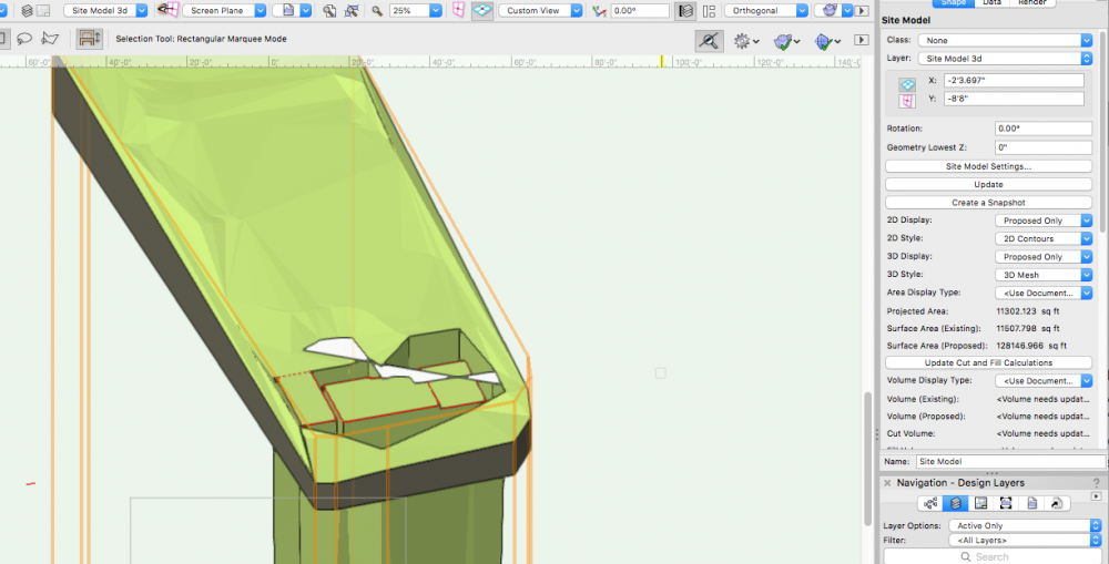
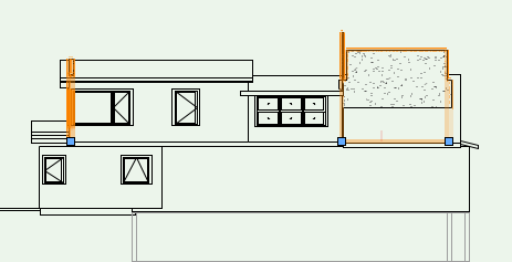
This just started happening: I create a crop object in a viewport on a sheet layer (either a square or a polygon) The crop object appears on my design layer, then shows up in the viewport. If there are multiple crops of the same design layer on different sheet layer viewports, all the crop objects show up in all of the viewports containing the design layer/ layers. This ONLY HAPPENS on the site plan. The site plans always contain imported dwg surveys. In the attached screen shot, the viewport crop object is the green rectangle and green polygon. These are actual objects that land in the design layer. I can delete them, but they appear again if I edit the design layer from the viewport. (i.e. right click > edit design layer My instinct is that this is somehow related to the autocad / dwg import, and maybe there's a setting i can turn off. Any ideas/ tips? Current workaround is delete delete delete- the crop object is placed in the design layer each time I edit the design layer from the viewport. Thank you.

-
Hello- I'm here to ask HOW to get a symbol into a worksheet??? VW2020 SP6/ macbook pro 2021 Montery 12.6 Thank you, julie
-
Locating notes database outside of VW
jtempleton replied to jtempleton's question in Troubleshooting
I am using VW 2020- and the notes were not found there, as expected. On a mac with finder window open- I clicked "go" from the top menu bar, held the option key down. This caused a menu option to appear for "Libraries" and there I found all of my notes databases going back to 2014. -
I used to know where my notes databases lived- and could navigate to them and copy/ paste into a word file. Is this still possible? I need to send a word (or similar) file to someone to use the general notes. Is it possible to get to the list of notes and copy/ paste them into a word document. Do the notes live in some sort of text document I can access.
-
Notes Manager / General Notes / Callouts Suggestions
jtempleton replied to _James's question in Wishlist - Feature and Content Requests
Amen. That is all. -
I was working in a VW file. I stupidly imported some autocad structural notes. After I did that all my viewports are still there, the annotations seem to be there for most of them. But the referenced viewport drawings are not showing. The proper layers are turned on, the proper classes are turned on. I've tried adjusting the crop thinking maybe something happened to the drawing origin. I have done a save as. I restarted VW. The design layer contents are still there. Any ideas on how to fix without starting over?
-
@Wes Gardnercircling back to this topic now that I have some time to dedicate to learning / improving. What is the method for "asking" a data tag for a door object to look for the desired door information in order to create a door schedule? I currently have an exterior door schedule, but would like to create an interior door schedule using data tags keyed to each particular size and type of door (vs the exterior door schedule where each door has a unique entry). It does not appear that I can create two separate door schedules using the create reformatted report command. Any tips for setting up separate interior and exterior door schedules? As best I can tell, I can do one via the create pre formatted report command, and the other would have to be done as a worksheet without linked record data in order to avoid combining two schedules of the same type. Thanks for your consideration.
-
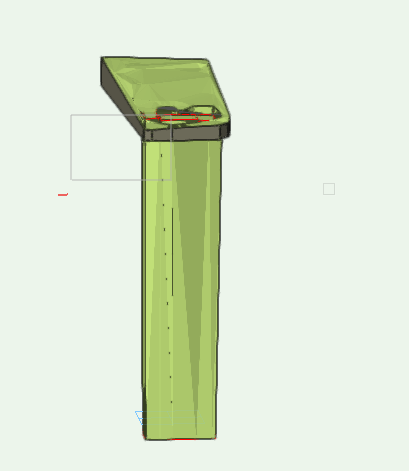
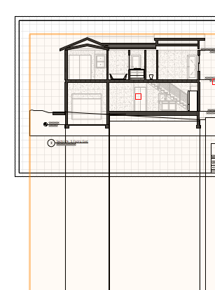
Hello, As I muddle my way through learning new (to me) features of VW on my own, I find myself stuck. In the meantime, seeking advice from the helpful community here. I have created a site model from survey data that is accurate enough for my needs. I've added pads where a new structure will go, one a bit lower for a garage, another a little higher for crawl space, and a third that is an existing slab in a garage that will be torn down. Will keep that slab. Elevations of the pad are roughly 221', 222' and 223'. The site ranges from about 221' to about 230' at it's highest point. (An urban single family lot). I have the site model set to a lowest elevation of about 218' so I have a little bit of thickness to it. When I add the site modifiers, it seems those default to a zero reference point. (I don't even know if I'm describing this correctly) Some screen shots attached. I guess if this is how they have to be, so be it, but I'd like to bring the bottom of the site modifiers up to align with the bottom of the site model. When I bring up the "Geometry Lowest X" it moves the whole model of course. So I keep that at zero. Workarounds, other elegant drafting solutions, tips, tricks and magic appreciated. The goal is really to automate the elevations and sections relative to the site so I don't have to draw in grade lines around the building, cross referencing the survey as I go along, and then having to make changes to that if the building height gets changed for whatever reason. I haven't figured out how to use this well with an elevation except to create a section viewport from a clip cube, with the clip just beyond the building, and apply soil hatch to the cut portions. Alas, I can't seem to change the cut plane- so where I've cut through part of a roof overhang with a clip cube, the fascia shows as soil. I suppose in a section view, the drawing solution would be to create the section as two viewports. One with the building, one with the site model, and create a crop object on the site viewport that cuts out the building area foundation walls and footings. My goal is good looking drawings with as much automation as possible. Also, this file crashes daily. Is that an issue others find when using site models?
-
@cberg - thank you. I'll try this.
-
Roof layer is above wall layer. I am not sure I can upload the whole file here. I tried one earlier and it never loaded. I think it would be too large. Walls that are not story aware seems to help. So does setting a wall height on the, in this case, second floor layer, that is well below the roof layer (as a workaround) rather than setting the second floor to the intended height.
-
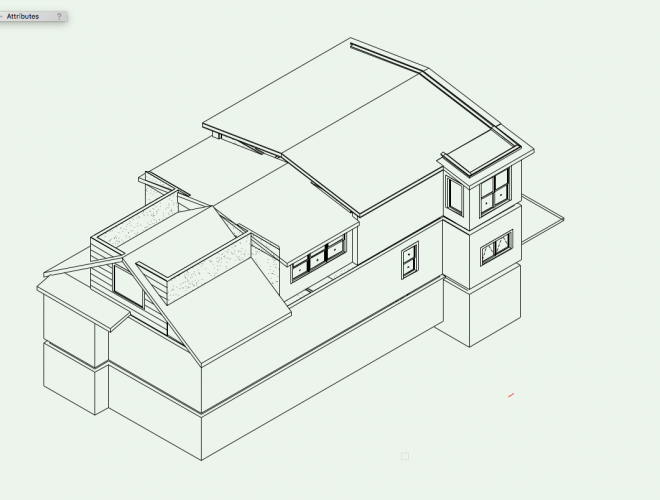
Hello friends- I have ongoing issues with walls fitting to roofs. This slows me down a lot when trying to create basic elevations. The resulting behavior when using this command sometimes works beautifully, but more often is erratic, producing undesired results (or none at all). My question is not about how to get the feature to work, because I think I've tried all the things. New layers, pasting into new files, saving as a new file, restart the program. Fiddle with wall settings & styles. Revise z location of roof layer to be slightly above the wall layer, and things of this nature. But if you have encountered something along those lines that works, I'm glad to hear about it. What I'm looking for is your best workarounds since I've given up on the feature working consistently. I need to stop wasting time trying to figure it out in every project. My solution so far is to draw over the roof and wall geometry to get the desired look in elevation and section viewports. This works fine, but when windows change, I also have to edit the polygons, if roof pitch changes, same thing. Looking for a better workflow and or magic. I do mostly small residential projects. Please advise. Running VW 2019 on MacBook pro w/ high sierra 10.13.6 NVIDIA T 750M 2048 MB Intel Iris Pro 1536 MB.
-
2021 Architecture Wishlist
jtempleton replied to Tom Klaber's question in Wishlist - Feature and Content Requests
@Amorphous - Julian yikes! so, core wall, 2 finishes, interior & exterior, then 3 empty opening to keep coordinated? i was thinking you might be onto something until I thought of that issue. 😜 Thanks for sharing your techniques though. Always helpful to learn new workflows and incorporate bits and pieces as they fit my needs. -
2021 Architecture Wishlist
jtempleton replied to Tom Klaber's question in Wishlist - Feature and Content Requests
@Amorphous - Julian how do you deal with windows in this scenario? -
@Wes Gardner thanks for the reply. I understand why annotations should be done in a viewport space. And I always aim to evolve as the technology does. But in terms of windows and doors, can you articulate why using data tags would be a better way to generate a window and door schedule, if that is your position? (vs. using the tags available in the window and door object settings) Do the two features work essentially the same way? I like the tag to show up in both plan and elevation view for my projects- do data tags accommodate that, or would I be placing double data tags to achieve that goal? Do you have any good idea/ tip/ workaround for compiling a skylight schedule, or is the "old fashioned" way, the best we can do at this time? I did search the forum to see if I could dig up any ideas/ suggestions, but did not come up with anything. Thank you for your reply. I really appreciate. - julie
-
I have skylights inserted into roof objects. I'm trying to determine the best way to collate them in a schedule, as the window and door schedule worksheet "create report" feature does. After looking at the data tag tool, it seems I'm not able to link tags to this type of object. Further, I'm not able to assign any sort of letter value using a number tag, and I'm not able to use the tag style for windows or doors, guessing because I'm not actually tagging that type of object. (I can place a window or door tag on a skylight, but I am not able to see or edit the text of the tag, and a yellow triangle with an exclamation mark appears in the tag). Would be great to have a way to automate this process more, but I am finding zero ways to automate, link, make it easier specifically for skylights. Any tips appreciated. In watching the video about data tags put out by Vectorworks ( I believe in September of 2018), I'm still a bit confused about how it works, and how to gain greatest functionality from the tool. The video seemed to suggest that the door and window tagging will be going away at some point in the future, so get to know the data tag tool. How do you deal with window and door schedules, and is there a way to break down schedules say by floor or story, and interior vs. exterior door types? Again, any tips appreciated.


