Nina Ivanova
-
Posts
348 -
Joined
-
Last visited
Content Type
Profiles
Forums
Events
Articles
Marionette
Store
Everything posted by Nina Ivanova
-
Thanks for the files, @OllieBSD! I looked at them and they seem very simple ones. Import was successful for all of them and graphics was properly created in a new design layer - I dragged and dropped each of the DWGs in a new blank document and used the Default DXF/DWG Import options. Resultant VW2021 documents are attached. I am not sure what might have went wrong with your import... Can I see an example Vectorworks document, created as a result of the import? ASH_DocM_S0684_2DDrwFt_NN.vwx IS_Attitude_A4592_2DDrwRt_NN.vwx IS_Strada_K082101_2DDrwFt_NN.vwx IS_Strada_K082101_2DDrwLt_NN.vwx
-
Hello @OllieBSD, There might not be any graphics in the DWG Model Space or you might have wrongly chosen to create symbols in the current document (if you use Import DXF/DWG or DWF menu command). Would it be possible to you to send an example DWG, which demonstrates the problem? You could send it directly to me. Thank you, Nina
-
Text justification when importing a dwg file
Nina Ivanova replied to Kevin K's question in Troubleshooting
@Kevin K, In general you should not have troubles to import the text alignment correctly. Can we, please, have the DWG file, so that we can check what is going on during import? You could send the file directly to me. Thanks, Nina -
Lack of memory message when exporting to DWG
Nina Ivanova replied to Okpaku's question in Troubleshooting
Hi @Jeremy Best, Yes, I received the document and confirmed, that the reported error is a false one. The problem was due to creation of a temporary symbol to represent the tile fills, but the name, which we tried to use for this symbol has been already taken. Failure to create the symbol was wrongly treated as lack of memory. As a workaround I proposed to Okpaku to not export tile fills, which worked for him. Problem is already fixed for VW2021 SP4. Best, Nina -
Lack of memory message when exporting to DWG
Nina Ivanova replied to Okpaku's question in Troubleshooting
@Okpaku, There might be a problem with export of some object, which is wrongly reported in that way. Would you, please, send the document directly to me, so that I could analyze the issue? -
Symbols not editable in DWG or DWF import?
Nina Ivanova replied to pdm's question in Troubleshooting
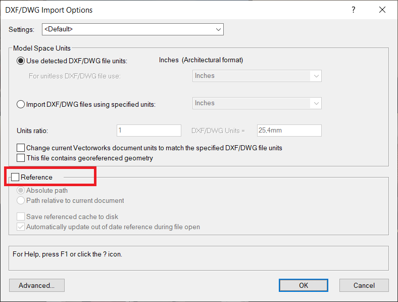
@pdm, It seems to me, that you are importing the DWG or DWF as reference. You should have the Reference checkbox set to OFF if you want to edit the drawing.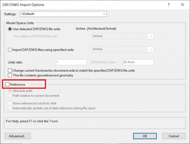
-
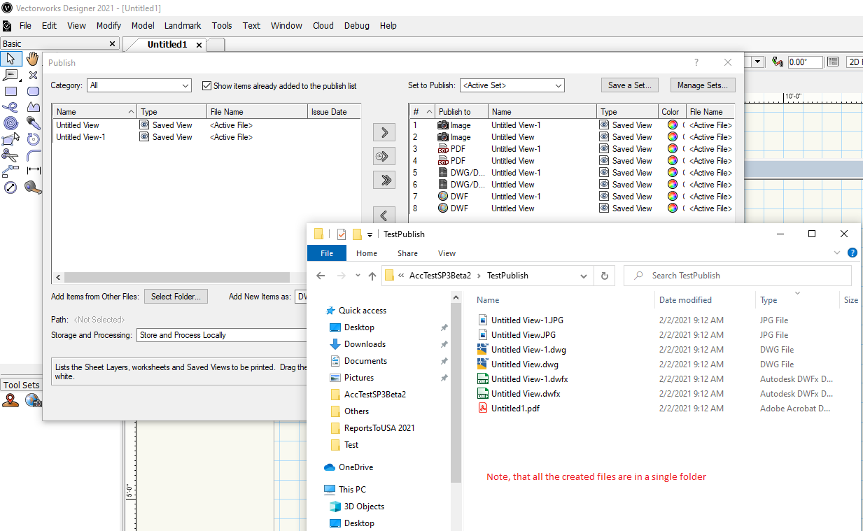
I don't want DWGs published into a separate folder!
Nina Ivanova replied to Christiaan's question in Wishlist - Feature and Content Requests
@_c_ Carlotta, You already have this option when you use Publish - please, see attached images.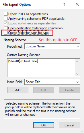

-
Hello @Stu Wilson, I am sorry to read that you have had so many troubles with DWG import... I downloaded the zip - it actually contains a big project with lots of referenced DWG files. What is your workflow to import the project files? Do you use our Import Single DWG menu and bind all the references inside a single document or do you use the approach with Vectorworks referencing (Import DXF/DWG or DWF menu command, References group options)? Do you import using the default import options? What Vectorworks version do you use and are you on a Win machine or on a Mac? I tried different approaches, but did not see a crash (VW2021 SP2, Win). Saw some issues, but they might be due to the differences in the way we present some of the objects or assigning some of them to classes with different visibility compared to DWG (this could happen and might be reasonable depending on the complexity of the original project). One of the things I saw, is that one of the DWG blocks has a line inside its definition from (0,0) to the rest of the graphics far away in the space, which is set to an invisible layer - the line extents are however used to calculate the proposed layer scale and switching to the Design layer in Vectorworks shows the real graphics as a point and you have to zoom there to see it. This is something, which comes from the original project, but you could control it choosing a better layer scale from the Model space scale options in the Advanced options dialog. If you want you might write directly to me. Thank you for reporting, Nina
-
Hello Magi, From what I see on the image and understand from the description, this is actually a different issue compared to the problems, described above. Yes, there are limitations set inside the third party library, which we use to create the DWG and DWF files. We pass the Vectorworks sheet sizes and what is done inside this library is to find the best matching sheet sizes and use them. We are currently working on a fix for an issue with the by-default set sizes when exporting from the Model space or as simplified graphics in the Model space (which is more related to the problems above) and might try to force the third party library to somehow accept our custom defined sizes. Thanks for reporting, Nina
-
@Ivaylo Stanchev, Would you, please, look at the previous post and work with the customer? Thanks!
-
And corresponding VW2020 version of the documents. BLK 27 - Level 1 v2020.vwx BLK 27 - Level 2 v2020.vwx BLK 27 - Level 3 v2020.vwx
-
Sure, @Matt Hagen, here they are. Best, Nina BLK 27 - Level 1.vwx BLK 27 - Level 2.vwx BLK 27 - Level 3.vwx
-
Hello Matt, We were able to see why the last char from the text is imported not as expected - the formatting is at the end of the DWG text, but it is actually not used for any of the text chars. The formatting has been wrongly added there - the DWG itself has not been originally created inside AutoCAD and actually such formatting cannot be added from inside there. AutoCAD however checks the case properly and shows the text correctly, while we have not expected such a case - right now, due to a failure to find a char, to which to apply it, we just apply it to the last char. An engineer worked on this issue and proposed a fix, which will be included in a future Vectorworks release/service pack. Until then, please use the attached document, which we created for you. Thank you for finding this problem and reporting it! Best regards, Nina BLK 27 - Ground Floor v2020.vwx BLK 27 - Ground Floor.vwx
-
Would you, please, send the DWG file directly to me? I will try to find the reason and fix it so that you are able to import the file in VW2020.
-
You are lucky 🙂 This was already fixed for SP2.
-
Trouble exporting to PDF, DWG or IFC
Nina Ivanova replied to Matt Hagen's question in Troubleshooting
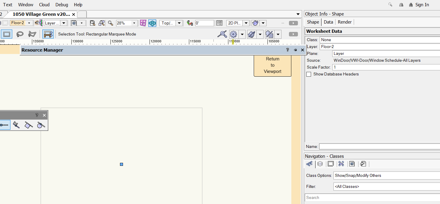
Thank you for the report, @Matt Hagen This delay appears to be due to the export of a worksheet data object with lots of elements, which for some reason is not visible in the drawing. We will work to optimize the process of export. Until you have the fix, you might create a copy of the document, remove the WinDoor/VWI-Door/Window Schedule-All Layers worksheet from the Resource Manager, which is anyway not visible on the drawing (see attached image) and export to DWG. Thanks, Nina
-
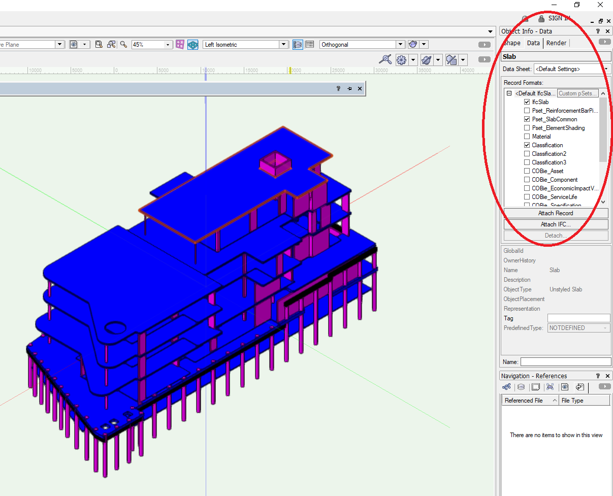
Hello @Victor S, Exporting the attached to your post document as it is results in creation of the Slab objects only in the IFC file - because Slabs have their own IFC data already attached to them. For all of the rest custom objects which you add in the document - like the extrudes in this example - you have to set the appropriate IFC data. You might want to read http://app-help.vectorworks.net/2020/eng/index.htm#t=VW2020_Guide%2FIFC%2FIFC_format_interoperability.htm and more specifically http://app-help.vectorworks.net/2020/eng/index.htm#t=VW2020_Guide%2FIFC%2FAssigning_IFC_data_to_objects.htm Hope this helps, Nina


-
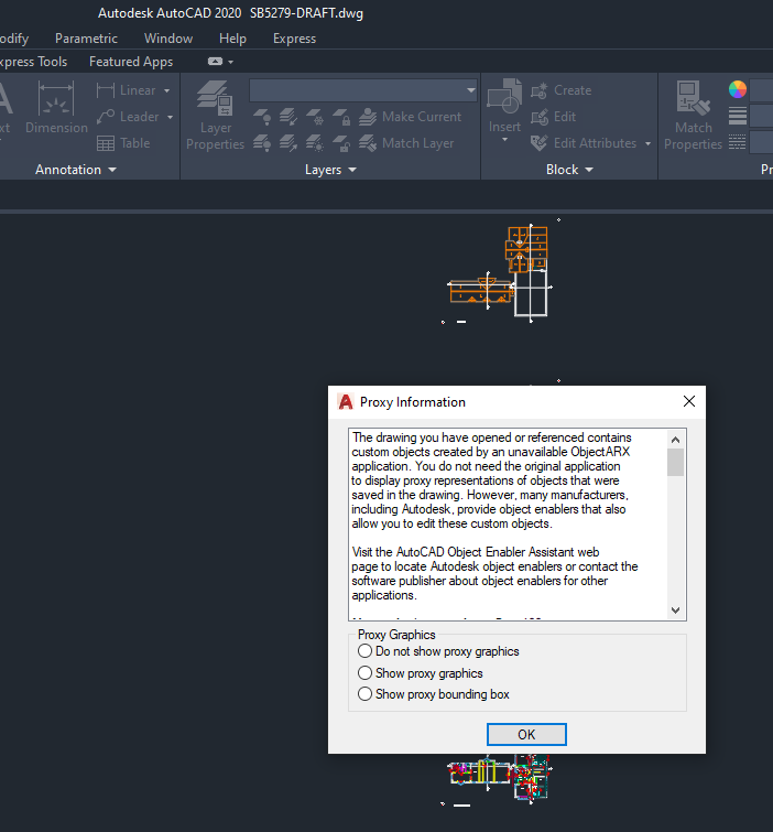
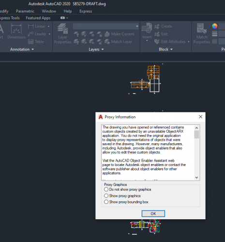
@michael john williams, this is what the regular AutoCAD 2020 gives to me when I try to open the DWG there: I do not know what AutoCAD version is using the surveyor, but there are some custom objects in the DWG. That is why we show the dialog in the beginning of the import too. For this exact DWG I did not see any graphics differences whatever option I chose from the above dialog - to not show proxy graphics, to show it or to show bounding boxes. Imported in Vectorworks graphics is identical to the graphics inside AutoCAD too.
-
Thanks 🙂
-
In this case you could just ignore the message. We use some data to recognize whether the DWG is saved by a Civil 3D, but filtering might need some tuning. Can we, please, have the DWG file to check why we show the message?
-
There is no DWG import fault - we just want to inform you, that DWG files, directly saved by Civil 3D, may contain pure Civil 3D objects, like our plugin objects, which a regular DWG reader might not be able to present properly - i.e. we will receive as info only the object bounding boxes and will create them instead of the real graphics. This will be a correct import, but may not be what you expect to see. From inside the Civil 3D there is a possibility to export the drawing as DWG - and when this command is used instead of the direct save as, complex Civil 3D objects will be saved with their full graphics and we will import it. Of course, if there are no such objects, import will be absolutely identical in both cases.
-
Importing dwg files in educational version
Nina Ivanova replied to Pauline Rossé's topic in Architecture
Please, check your import options - you might have chosen to import the DWG as a reference. -
Thank you for sharing the document, Matt! I can confirm the delay when working with the document. From what I see there, you have either imported the DWG in an already existing Vectorworks document, or have updated it later adding more staff. Or you might have imported multiple DWG files - probably 267 according to the number of Design layers? The rest of the things, which I found: - The document contains nearly 4 735 000 objects, screen plane; - Created symbols are 97623; There are also lots of groups; - Imported hatches are actually groups with lines - Vectorworks imports hatches as hatches, does not decompose them - so probably this is how the DWG file has been exported by ArchiCAD; - Seems that dimensions are also presented as groups of lines and text - by default we import dimensions as dimensions, except if the linear scale parameter is different than 1.0 or you have explicitly chosen to import them as groups; - There are 350-400 classes and 71 sheet layers; I will create a performance issue and will attach this document there so that our engineers could look at it and work on improvements. Thank you, Nina


-
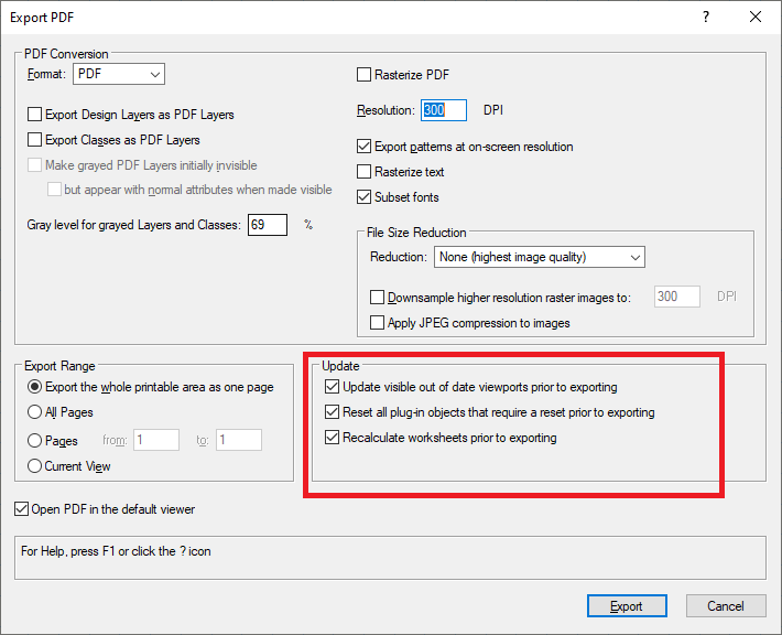
Please, try with changed Update options. Does it help?

- 1 reply
-
- 1
-

-
@NeedHelp, Publish to PDF is not allowed in Fundamentals. I am attaching a link to the Publish functionality help page: http://app-help.vectorworks.net/2020/eng/index.htm#t=VW2020_Guide%2FPrintPublish%2FBatch_publishing.htm%23CSH_6