ashot
-
Posts
81 -
Joined
-
Last visited
Content Type
Profiles
Forums
Events
Articles
Marionette
Store
Everything posted by ashot
-
my Third Post C) OK - ODBC Share

-
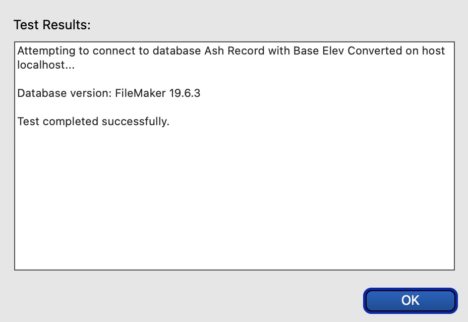
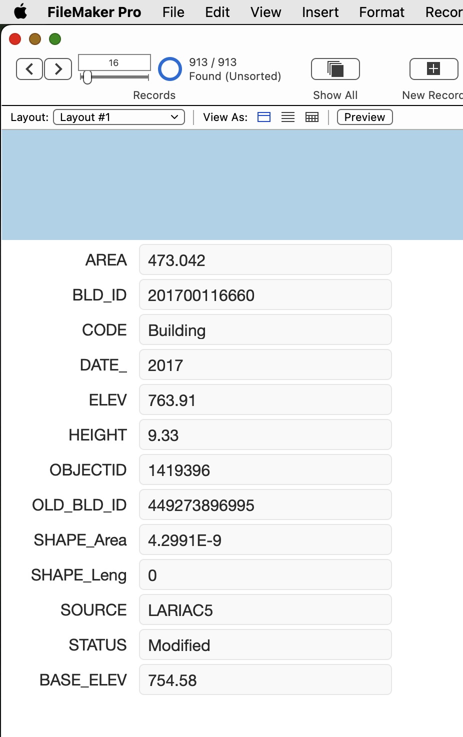
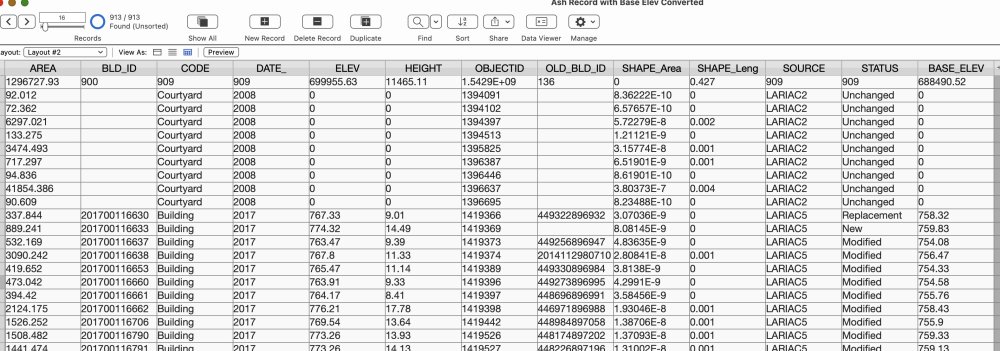
My Second Post B) OK - for FileMaker Pro 16.3 Setup for Sharing
-
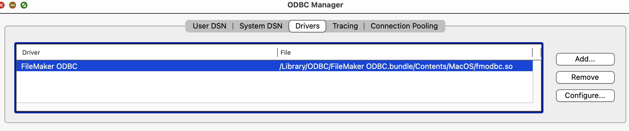
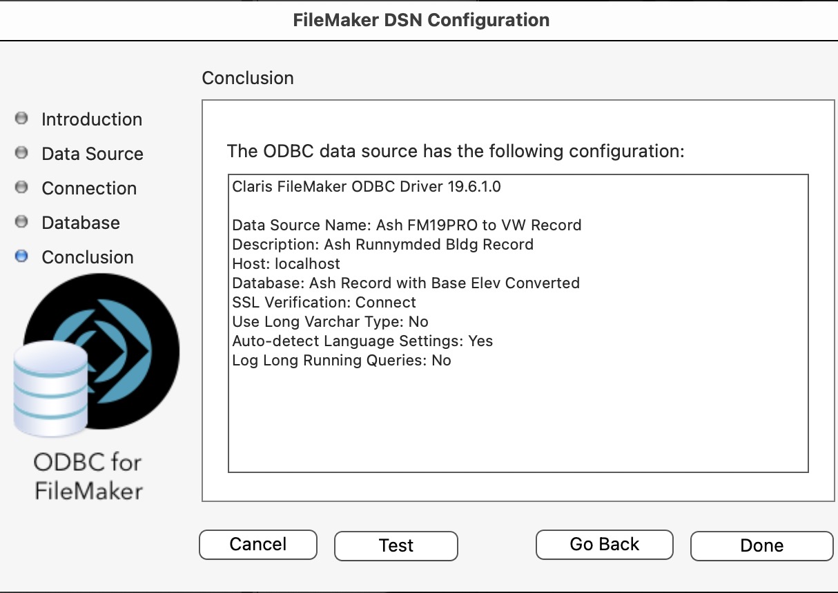
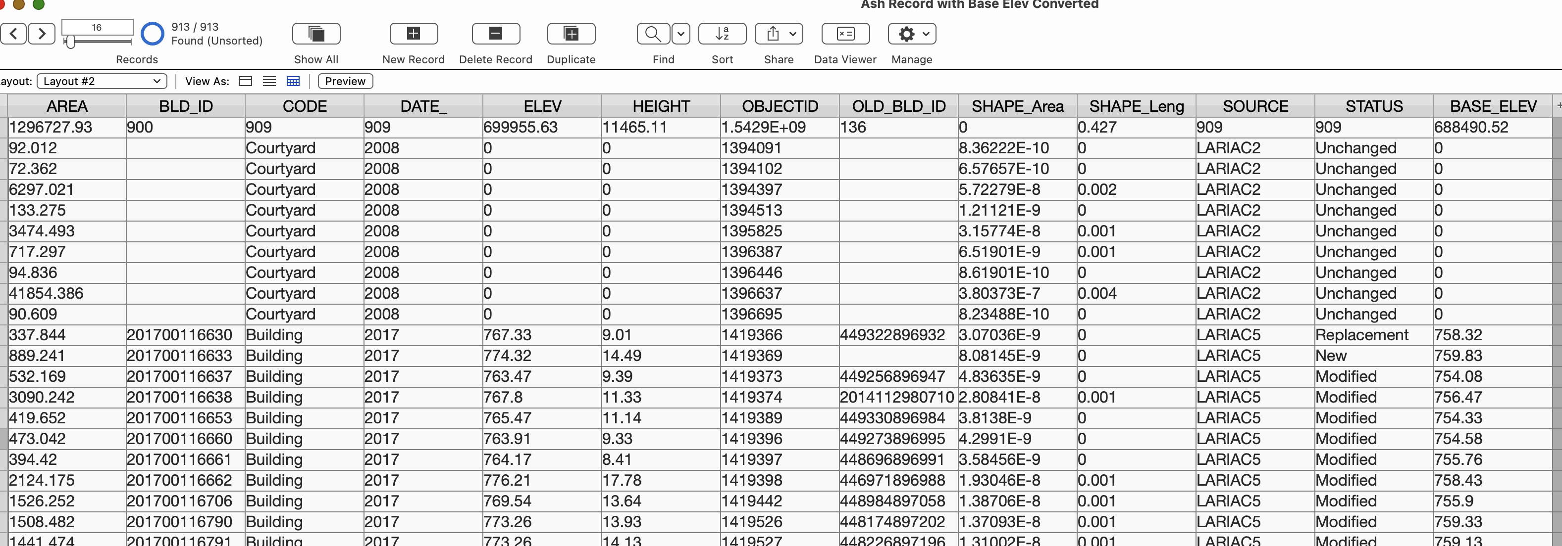
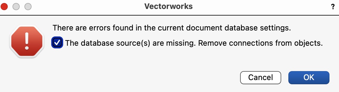
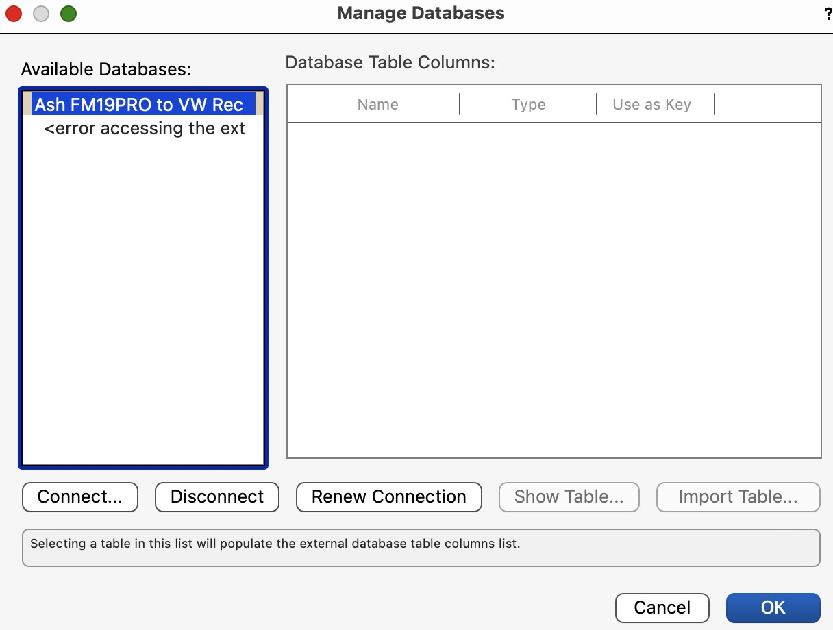
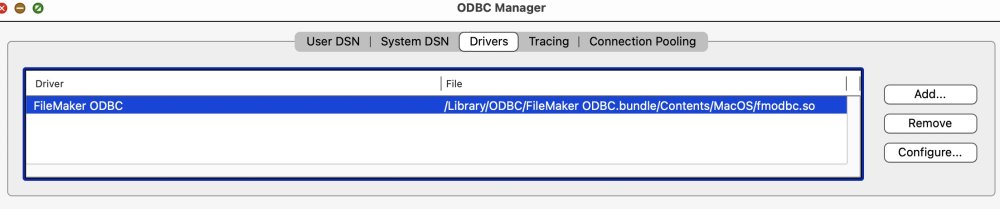
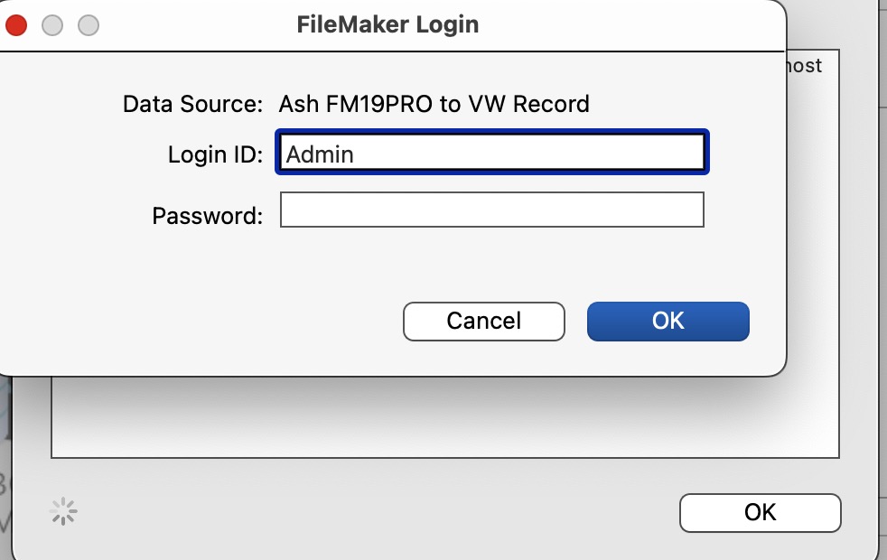
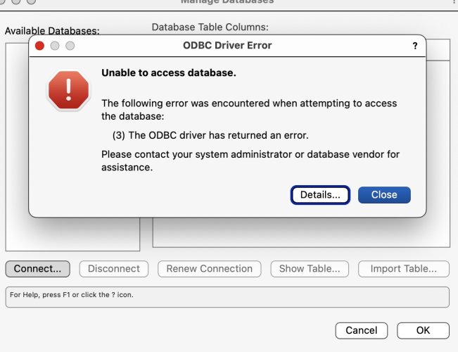
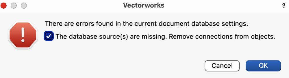
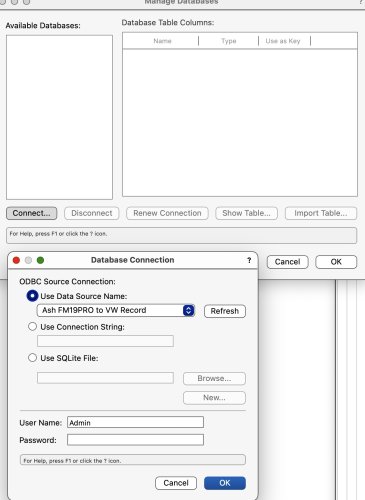
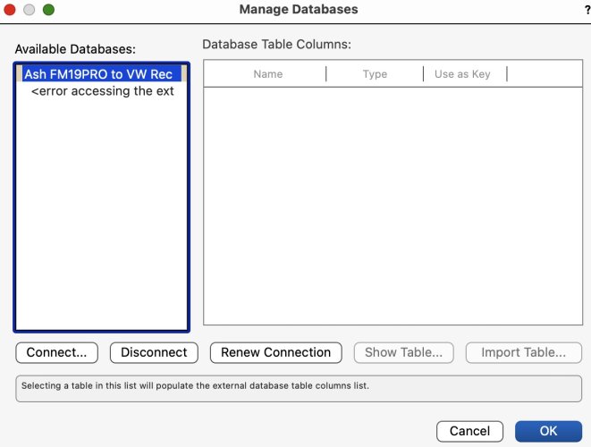
About "link to database" via ODBC on a Mac Using 64-bit ODBC Manager 1.0.2.2 on a Mac I can see, test, access to my Filemaker PRO v19.6.3 Database from other applications such as Excel. But I am getting the Driver Error all the time when I try to do this using Vectorworks. Any help will be greatly appreciated. DRIVER ERROR IM004 SQLAllocEnv () FAILED (by the way SQL AllocEnv should not be used by the Driver, since it is depreciated after 2016, and replaced with SQLAllocHandle () https://learn.microsoft.com/en-us/sql/odbc/reference/syntax/sqlallocenv-function?view=sql-server-ver16 In a backward sequence I will make four posts starting with this first post message to show: A - Error Vectorworks NOT GOOD B - FileMaker OK C - ODBC Share OK D - Excel OK Below is the first A - Post with Screenshots:

-

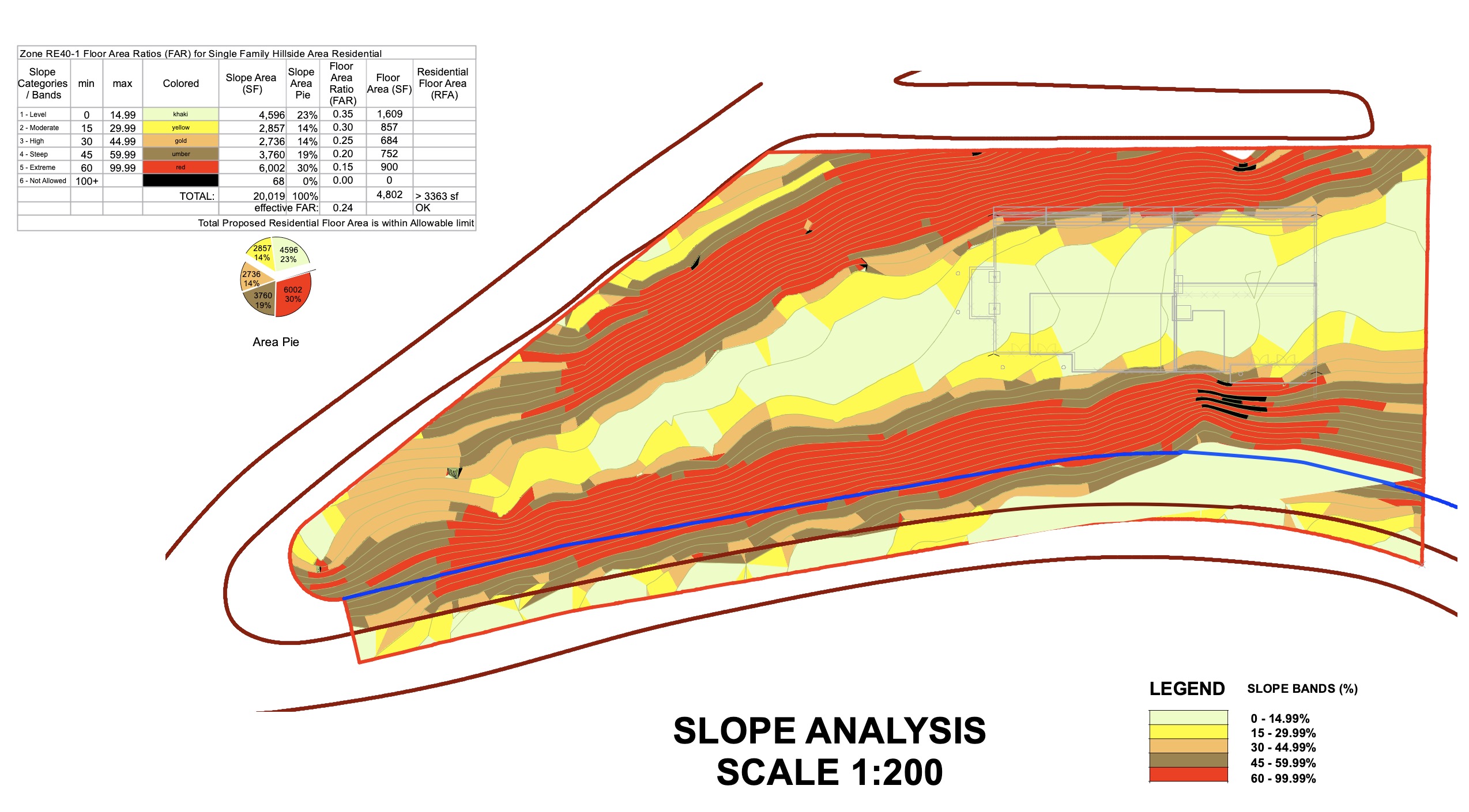
GEOTECH DATA IMPORT FOR SITE MODEL COMPONENTS
ashot replied to Phillip Tripp's topic in General Discussion
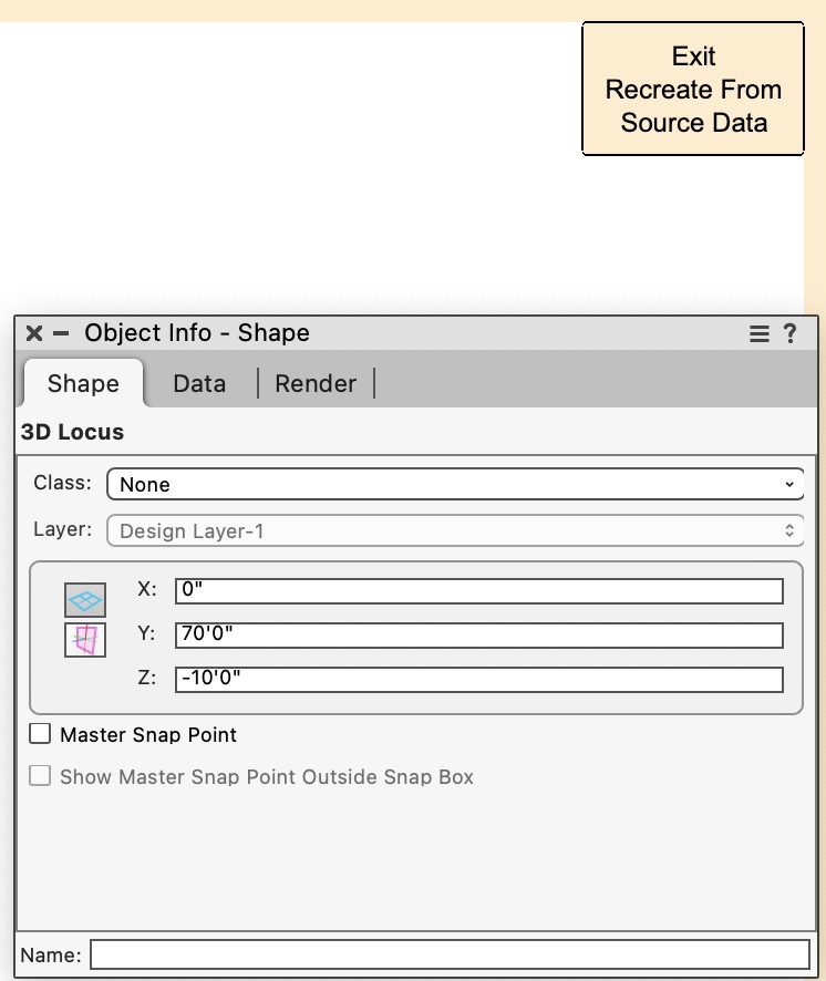
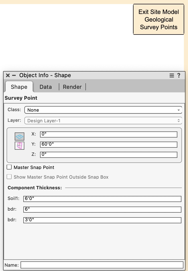
Can anyone help: Is there a way to convert Stake Object or 3D Locus into Survey Point, see screenshots of OIP for each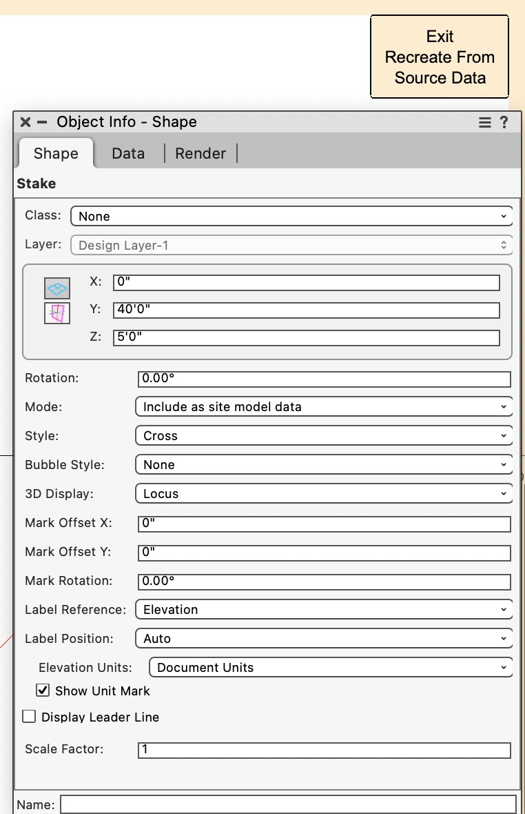
-
GEOTECH DATA IMPORT FOR SITE MODEL COMPONENTS
ashot replied to Phillip Tripp's topic in General Discussion
First Step is to add Site Model Components Then you can access Geological Survey Points from the same dialog Attached is Vectorworks 2023 Test file (trimmed) Check Design Layer Site MODEL OIP: Edit Geological Survey Points 2023-09 VW for Test trimmed.vwx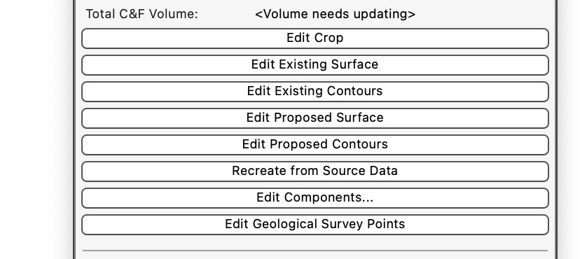
-
Go Edit VP Annotation, Select Similar Tool, for Preference for Selection - check only Class and object Type, click on Drawing Label, see how many you have on OIP. When more than one, I would Delete all, and create new label again.
-
GEOTECH DATA IMPORT FOR SITE MODEL COMPONENTS
ashot replied to Phillip Tripp's topic in General Discussion
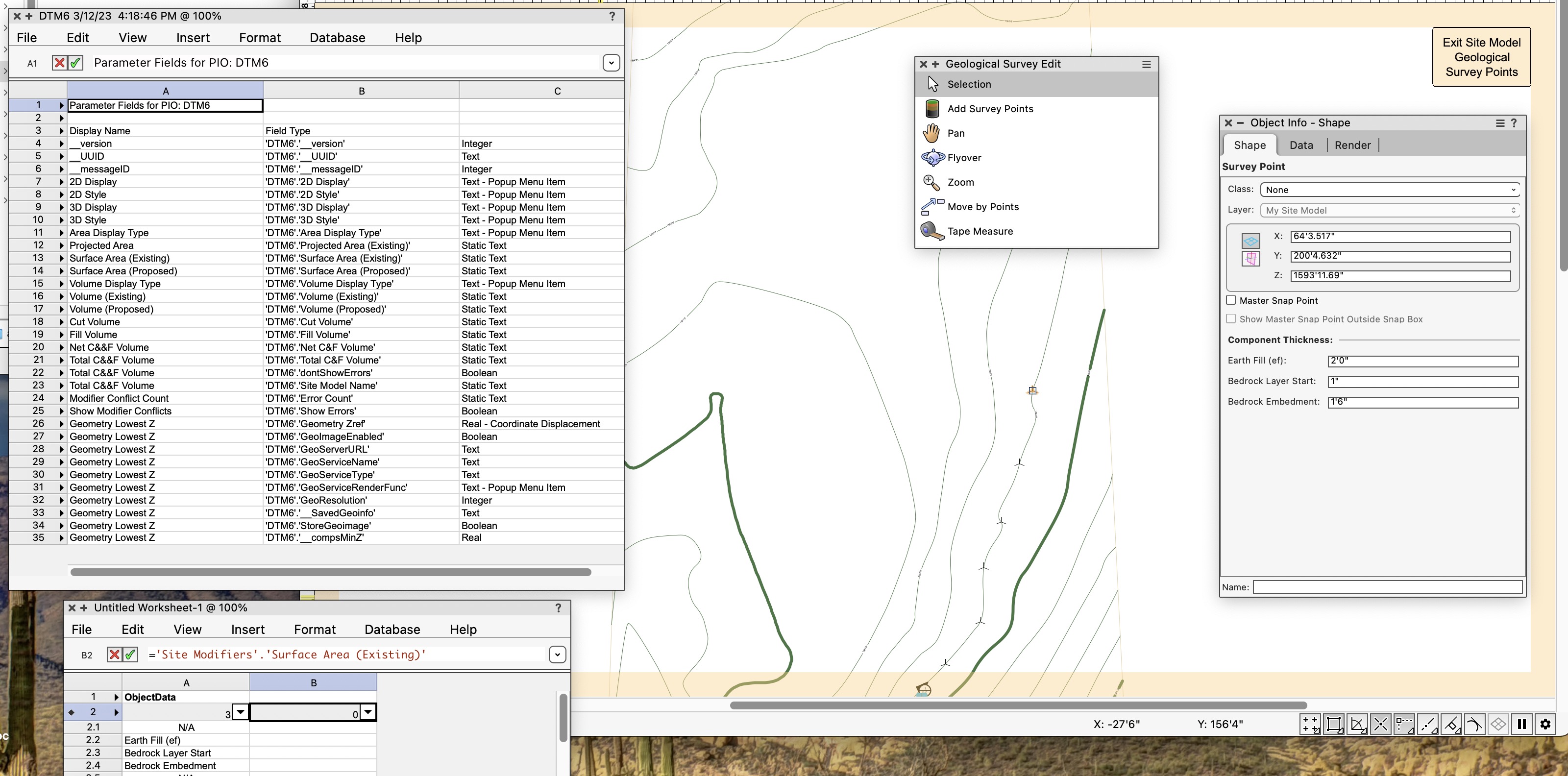
If I add survey points manually, the soil layer components will be derived from preferences of site model components and their thickness. You can change the thickness for survey point layers to anything and sometimes to 0 if layer is missing at that spot, but you need to make sure all the layers are defined in Site model components first before adding survey points. Also after defining survey point, the default layer thickness for site model component no longer applies. The survey point makes new rule and overrides the default. Even with one survey point, all site model assumes that point to be consistent everywhere. So it is necessary to put as many survey points as you need to mimic existing condition. Importing survey from survey file is a good approach. However, in my practice soil engineer shows only data for few pits, the rest is assumed from their section diagram. So basically I start with a row of new survey points, make them the same elevation Z. then copy and move to new location and change the elevation for new row, etc. Now I have a question about showing survey points in a Worksheet. Patrick Stanford probably can help here. I can NOT find the criteria to show survey points. Please help. See attached: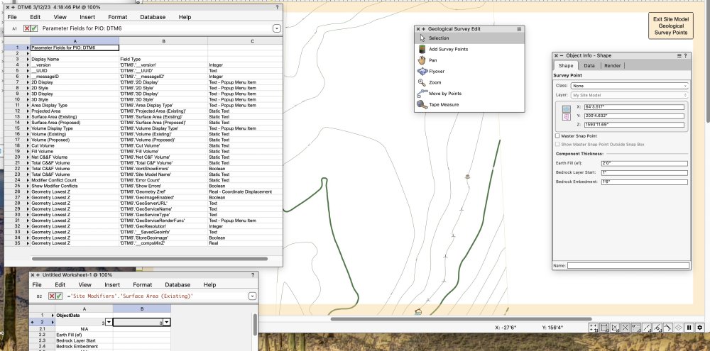
-
2 displays and Moom App to control palette layout
ashot replied to bob cleaver's topic in General Discussion
After initial placing all pallets on my second screen I get consistent palette setup every time I log on or open VW by choosing once "Window->Pallets->Save Pallet Position". Obviously it has nothing to do with Moom app, but it serves the goal. -
in my opinion, Pat is right, I agree, the last two values: Fillet Radius and Bottom Flange thickness
-
Render Time 15:00 OSX Ventura 13.2 VW 2023 SP3 (Build 684728) (64 bit) 2017 iMac Pro purchased for $6,600 from Apple 64GB RAM 3.2 GHZ 8 core Xeon W Graphic card:Radeon ProVega 64 16GB
-
Very nice. Where can we purchase or download The Font you used in your file: Architects Daughter Revised: I Found it on fonts.Google.com
-
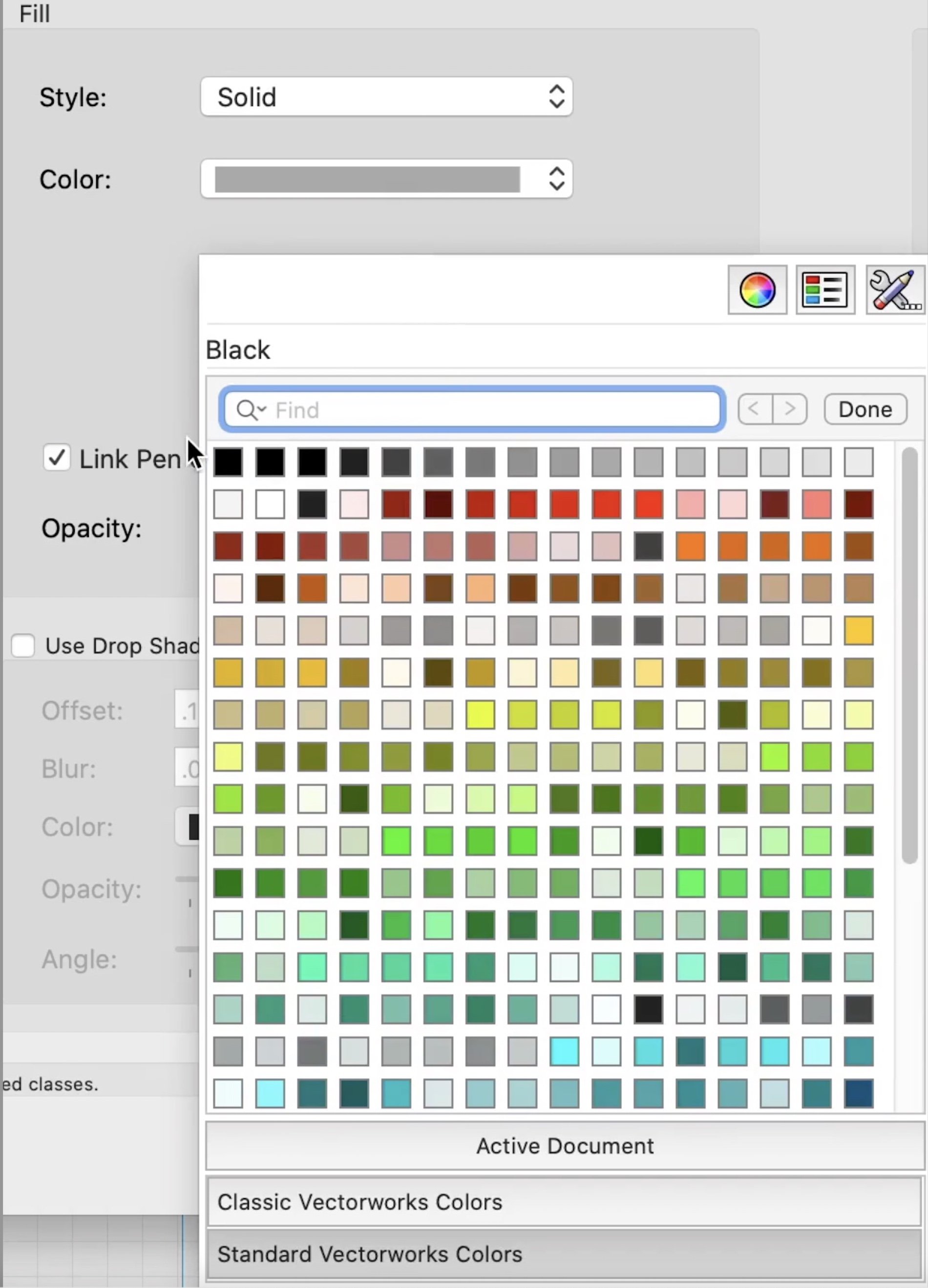
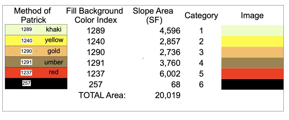
Pat, thank you for help, for your time and effort. I guess the Index for Active document color palette is the only option. After making a copy of 16x16 existing color palette, for example Classic colors, do you know how I can make it default to replace active document color palette.
-
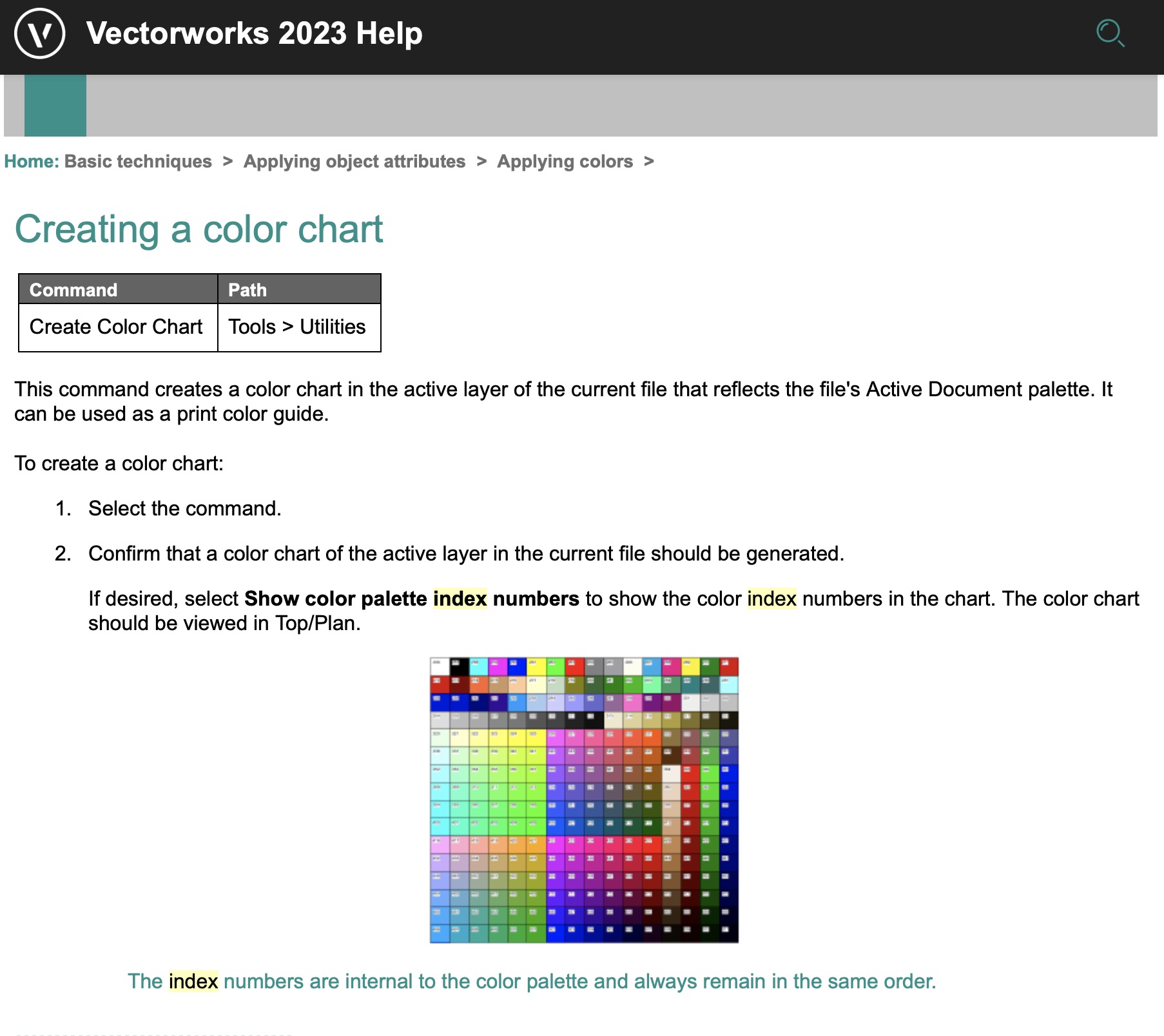
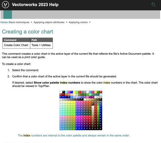
Index Numbers are internal to the color palette and always remain in the same order. Is this about Active document Palette or any other palette?
-
-

-
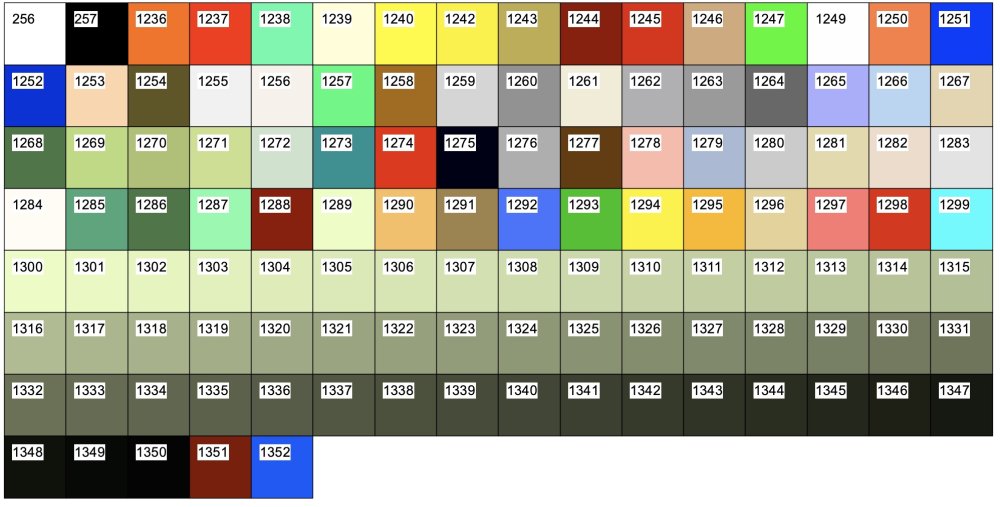
Question 1) Is there a script to show Color Index for VW colors from a particular Color Palette. Also a script to convert RGB to Index or Index to RGB. It is usefull to use Tools > Utilities > Create Color Chart to show the index number. However it shows numbers only for Active Document Palette. Also, I wonder if there is a way to get Index Numbers for Standard Colors for example, without bringing colors one by one into Active document? Question 2) Is there a way to bring many colors into Active document at once? We can make a copy of Standard Color Palette and then delete colors we don't want, but can we delete several colors at once?
-
in VW 2022 can't see the change for "gap line length" in OIP for Section Line. Can anyone show the effect on a smaple drawing?
-
We need to keep actual Z at DTM Surveyor level, Make all Building and Structures with every Story Z to be at actual Elevation and/or Send to Surface. This means the Datum must be set 0.0 (Z) = DTM 6750 ft as an example for Big Bear Lake property on Hillside. Any benchmark will be correct, all sections and elevations correct. Except this creates the same problem as making application internal 0.0 far way from Model 0.0 (Z) = DTM 6750. There many instances when planar objects created on actual 0.0 (like Section Line instances etc) and in order to see them I spend time zooming (in-out) to send them to correct elevation visible for viewports. So why VW allow us to set Origin 0.0 (X,Y) to anything in Georeferencing, but ignore to do the same for (Z) value - is a mystery for me. Any ideas?
-
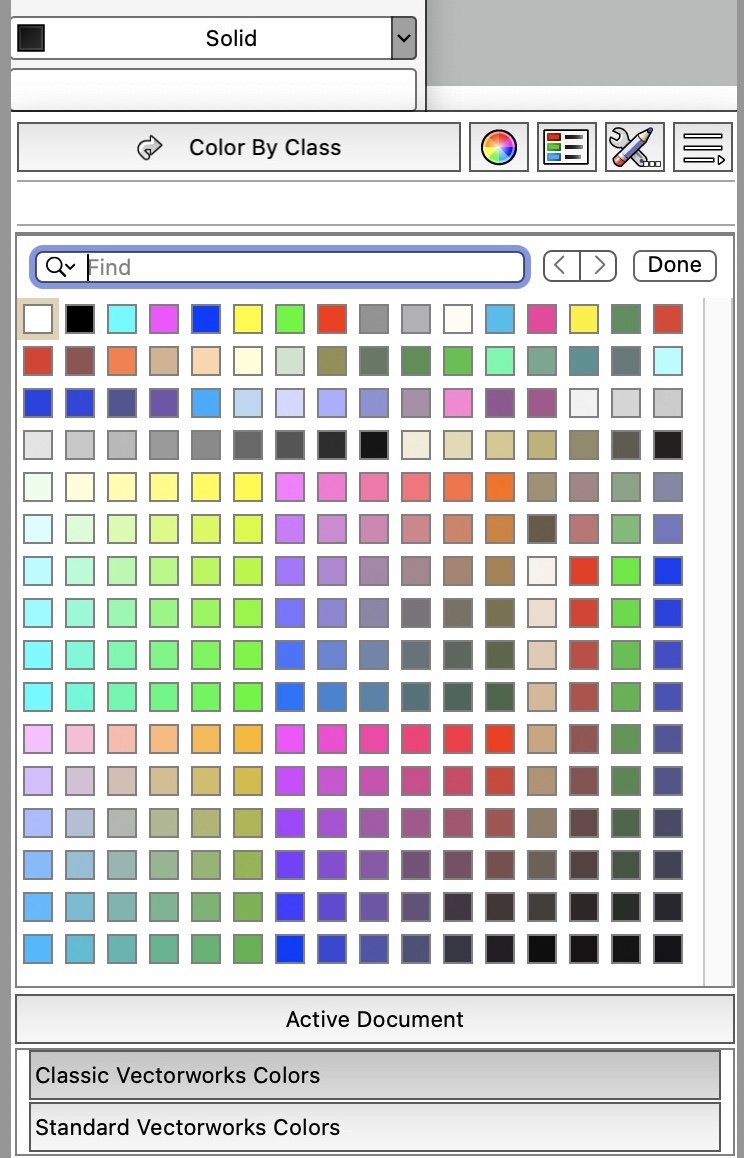
While checking University videos for 2021 Core Certification, I noticed color palette had classic standard names but different color layout. It would be OK if the names for palette indicated that they were modified by editing the standard. However since they have the same name "Classic Vectorworks Colors" & "Standard Vectorworks Colors" I wonder if anyone else can confirm which of the two palettes are really standard. Please see attache two screenshots to compare "Classic Vectorworks Colors":

-
Can you please make the wrapper with English subtitles?
-
Interiorcad beginner questions
ashot replied to michaelk's topic in 3rd Party Services, Products and Events
I understand the need to add my first line. I just can do not have a clue how Texture and new material name is read by the program. I do not see my new line in the pop-up menu for materials and types. Please see attached and advise.
-
Interiorcad beginner questions
ashot replied to michaelk's topic in 3rd Party Services, Products and Events
Dear Nicolas, thank you for your help. In my XG library for Imperial Materials the data shows mm and m2. Also I am not sure if for Solid Wood I can find the right Group in the table. None of items in the Material table has a group or texture I want to use. All I need is a "Test Material 3/4" thick with Custom Texture". What will my first line be listed here instead the Chipboard 04 ...
-
Interiorcad beginner questions
ashot replied to michaelk's topic in 3rd Party Services, Products and Events
I am using interiorcad XS. In my case, what is the Path and how can I assign new material in >Boards ? -
Interiorcad beginner questions
ashot replied to michaelk's topic in 3rd Party Services, Products and Events
1) In my version of interiorcad XS the Settings does not have preferences. Instead it shows Version Info with User Settings/Path to XG Resource, Datea with Version, Plugins Path and Export User Folder Path. I do not have Preferences> Database to shoose a table. 2) Also in all XG folders the files are text files. What kind of file format do I need to create for Material to place here? All I want is to have a new Solid Material 3/4" thick without any edge bordering or veneer, to make only one texture and change it on a spot when the client demands, for the entire cabinet, provided I can also change the glass for framed doors.