


Guillemot
-
Posts
9 -
Joined
-
Last visited
Content Type
Profiles
Forums
Events
Articles
Marionette
Store
Everything posted by Guillemot
-
I found it. I was looking under Vectorworks Preferences instead of Document Preferences. Under "Legacy 2D" I turned on "Turn Off Unified View". "Ignore Layers with Different Scale" under "Display" allows other layers of different scales to be displayed, but it displays them at the same scale as the active layer. Useful, but not what I needed.

-
I've got 2 different scales appearing in the same drawing. Currently the layers only show other layers of the same scale. There used to be a way to work with Stacked Sheets/Unified View/Legacy functions to get all layers of different scales showing at the same time. I can't find anything like it now. What is the new system to accomplish this?
-
Complex Line Types with Polygons vs Polylines
Guillemot replied to Guillemot's question in Troubleshooting
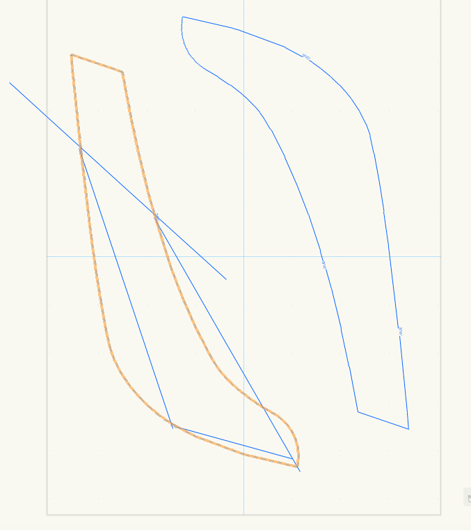
The line length is the length that I want for the appearance I am seeking. It does help if I break the line into shorter segments by chopping it up with the Split Tool, but it really only makes the errors harder to notice. The Type does not have trouble rotating around the curve on a polygon. The sample on the left is polyline with short split segments in the Line Type, the right is polygon with the same Line Type. The line does match better, but at hard corners and around arc segments the line varies off the intended path. Converting to Polygon is a viable workaround in a lot of situations but loses information, and it would seem to be appropriate to be able to use Line Styles on polylines and have them actually follow the path shape. It took me quite a bit of time to figure out that the problem was caused by the polyline. It isn't obvious that one should work and the other should not.
-
The enclosed image shows the same shape, the one on the left is a polyline, the one on the right is a polygon. Both have the exact same complex line type showing in blue. I am hovering over the polyline on the left to show the orange shape. The complex line type on the polyline displays as a series of the line definitions situated around the polyline, they are straight and do not follow the shape of the polyline. I.e. it is completely unusable. I can convert it to a polygon, but this loses information and makes it less editable. Is this a known issue? Is it intentional?
-
If it was a snake it would have bit me. Thanks. That did untrim the surfaces. But it looks like Vectorworks can not handle the surfaces. When I hit untrim, the surfaces disappeared. The vertices remained, but the surface is not drawn. With one surface I was able to create an interpolated surface (Not a great representation), but the other it just gave me a "Create NURBS Surface failed" error. "Rebuild NURBS…" fails as does "Extend NURBS…" It think this likely relates to an ongoing problem I have had with Vectorworks from multiple versions back where it is unable to deal with NURBS containing congruent control points.
-
I've imported some NURBS created in MaxSurf, a naval architecture package, into Vectorworks. I would like to do some more manipulation. They come in as trimmed surfaces, even though I have not been trimmed them. Is there a way to untrim NURBS surfaces returning them to their "full" size?
-
Thanks, editing the workspace seemed to do the trick.
-
quote: Originally posted by mike m oz: View / Rendering / Line Render Options... This does not appear to be an option. I've got Vectorworks 11.5.0 and Renderworks. Is this option only available with one of the industry packages (Architect, Mechanical, etc)?
-
Version 10 had the "Smoothing Angle" that could be set in Document Preferences. Is there an equivalent setting in 11.5? I have fairly smooth polygons that I am extruding. When rendered in Hidden Line mode I don't want a line connecting each face at every vertex. Any suggestions?
