


markdd
-
Posts
3,411 -
Joined
-
Last visited
Content Type
Profiles
Forums
Events
Articles
Marionette
Store
Everything posted by markdd
-
Better access to Section Line Instances dialog
markdd replied to Tom W.'s question in Wishlist - Feature and Content Requests
Indeed. This workflow could definitely be speeded up. -
The only way that I know of is by adding the several solids together as a Solid addition. Objects do not need to be touching or overlapping to become a solid addition.
-
Truss defaulting to 3D symbol in plan view in Spotlight
markdd replied to symo's question in Troubleshooting
Is it every type of truss or just a certain type? -
I think the questioner actually meant Spotlight Lighting Devices…….
-
This is a known bug in 2024 and my understanding is that it’s being worked on.
-
Why can't I replace a symbol with a new symbol of the same name?
markdd replied to Pewabic Detroit's question in Troubleshooting
Basically, the behavior you are describing has always existed. However, I do remember last year or maybe the year before that there was a brief period when if you created a Symbol with the same name, a dialog opened telling you that and then asking whether you wanted to overwrite the old one. For some reason, that functionality was removed. I don't know why because it was most welcome....- 1 reply
-
- 1
-

-
Line direction arrow just started appearing in sheets
markdd replied to Shortnort's question in Troubleshooting
Somewhere along the line, I expect that the class the walls have been assigned to has had marker arrow attributes turned on. Take a look in the Object Information Palette entry for a selected wall and you’ll probably see the arrows indicated. -
It's in the Edit Group options button.
-
LED Screen Tool: Curved Screens
markdd replied to Andy Broomell's question in Wishlist - Feature and Content Requests
@Tommy-PixelSometimes it’s best to see what’s going on. Can you either post the relevant objects and texture into a blank file and either post it here or message me with it and I’ll take a look this evening and report back. -
Attach Record to multiple symbols in the Resourse Browser?
markdd replied to Bruce Kieffer's topic in General Discussion
Attach record Command should do it. You’ll need to put your symbols intro folders to use the command efficiently though. -
It is possible to do this, but not exactly as is shown in Vectorwork Marketing which are just manually drawn lines. Go to Spotlight Preferences and the Classes and Colors section. Check the Show beam Angle - center line box and uncheck the others. You can also assign a Class as well so you can turn this feature off using a Class. Go back to the Lighting Device and select Draw Beam in the Object information Palette. You should have a single line between the Lighting device and the Focus Point.
-
The inventories that are generated from the files are stored as xml files in the inventory folder contained in your library. If you won’t be working at a venue again, then can you not just delete the specific inventory from the inventory section dialog?
-
You are doing nothing wrong. This definitely should not be a feature. I will bug submit this and see what comes back. Filed - VB-199658: Changing X,Y, or Z rotation of Lighting Devices - Unexpected behavior
-
@Stephan Moenninghoff should know.
-
Layer Colour Overrides. Yes, I know it seems somewhat abstract!
-
On my Mac, "U" toggles the first two buttons (mode group 1), "I" toggles the second pair of buttons (mode Group 2) "V" activates the Options button (mode group 3) and opens the dialog and "P" allows me to enter a value into the distance field (Mode 4) when distance mode is active in Mode group 1. That is how I expect it to work and I am having no problems with my installation. There may be a problem with Windows, which I can see from your signature you are using. If you are having a problem with the P key for mode group 4, check in the Workspace Editor that P is assigned to the 4th mode of Tool Mode Groups.
-
The distance field is not available if the Second mode if the Offset Tool is active. Is it unavailable for all modes of the tool?
-
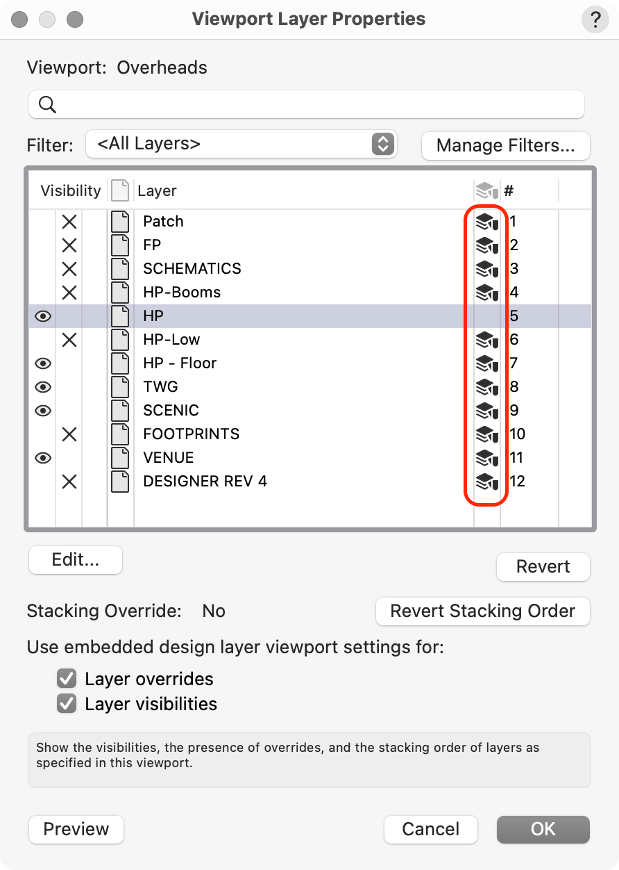
You need to use the Layer Colours options that can be accessed by pressing the Viewport's Layers button. By default, I think all Layer Colours are set to Black and White, so it should be very quick to override all the layers except the one you want to remain in colour.
-
Toggle to Select From Overlapping Objects
markdd replied to rudybeuc@gmail.com's topic in General Discussion
Yes. You need to use the Select Coincident Object command. Hover over the geometry of the overlapping objects and an asterisk will appear beside your cursor. Right-click or Click and hold down the J key and choose Select Coincident objects. A list of objects will open and you can then select the correct object from the list. Hope that is what you need. -
Yes. Use the Taper Face Tool in the 3D modeling Toolset.
-
Array a 2D object along a 2D irregular polyline
markdd replied to unearthed's topic in General Discussion
Thee is also the custom Line type route if that is more appropriate and takes about the same time to set up. -
Collaborating in real time, same file
markdd replied to oliver.williams's question in Troubleshooting
You should investigate the Vectorworks Project Sharing feature. This should do what you need. -
Using "Base Plates" with papes and truss's
markdd replied to Cristiano Alves's topic in Entertainment
@Kevin Allen Lighting Devices, Speakers, Video screens, etc. have to connect to Rigging Objects such as Truss or Hanging Positions somehow. Most connect using a Boom arm, bracket, or whatever is needed at the time. Some of this equipment is generic and some is highly specific depending on the object that is being attached. My use of Point Loads enables me to bridge that gap a little between the rigging object (Truss or Boom) and the Load (in my case a Lighting Device) but Point Loads are not versatile enough, especially given the multiple ways that users now want to display these 3D objects in their drawings. I see so many users trying to invent workarounds for this kind of thing because their expectations have started to overtake the software that they are using. Because so much detail can now be shown in renderings and sections, users now want their plots to be more and more realistic. This includes the rigging hardware. Not so long ago lighting designers never felt the need to show this kind of gear on the plot, but now, because of the advances in the Vectorworks software and the need for users to previsualize more and more, rigging items such as boom arms, brackets and the like now need to be shown. This means that we need to have a way of manipulating these items in 3D as well as reporting correct 2D geometry in Top/Plan and in Schematic Views. All this as well as the ability to pass the relevant load data to whatever part of the software that needs to see it. If a really great way can be found to engineer this functionality into existing objects, then fantastic, but I suspect that it may not be versatile enough for some of the users I have worked with over the last few years. -
Using "Base Plates" with papes and truss's
markdd replied to Cristiano Alves's topic in Entertainment
Hi Steve Point Loads and Distributed Loads are both added to the drawing using the Rigging Loads Tool. You can add a Symbol to a Point Load, and if the Symbol has a 2D Hybrid component, then it will show up on a Schematic View. When I have created a Point Load with a symbol such as a Boom Arm, or a Boom base, then I save the finished item as a Red Plug-in Symbol. I have a specific Boom Kit favorites folder full of Point Loads for this purpose. When I double-click on the Red symbol listing in the RM, the Rigging Load tool is activated and I can then attach the item to a boom (or any other rigging item I like in a similar way to adding Lighting Devices) and the load will be added to the Rigging object and it will be part of the Rigging System. @Scott C. Parker That is essentially my workflow. It is also something that I would very much like Vectorworks to develop into a new tool that would bridge this gap between Lighting Devices and Rigging Positions. Ideally, I would like something that combines the functionality of the Lighting Device and a Point Load into one new object that can respond to changes made to Rigging Positions and Rigging Loads such as Lights, Speakers etc. Hope that answers your question.... -
I don't know what the exact rationale is for the menu option. However, there is always the menu command to which you can add a short cut as well as a Right-Click Working Plane menu option if that is how you like to roll. Personally, I find going to the View Bar a bit of a chore and use a keyboard shortcut to activate the command instead.