markdd
-
Posts
3,411 -
Joined
-
Last visited
Content Type
Profiles
Forums
Events
Articles
Marionette
Store
Everything posted by markdd
-
Check the Insertion point modes when the Insertion tool is activated. You need to have it on the fourth "Insertion Point" mode.
-
For what it’s worth that’s my process as well…..
-
Viewing/Hiding lighting device symbols for designing and viewports
markdd replied to jloganthomas's topic in Entertainment
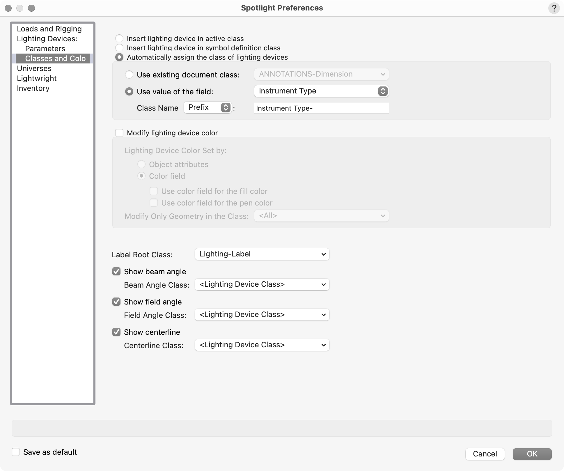
Probably the best built-in way is to automatically Class them. This can be done automatically by using Spotlight Preferences and Classing By Instrument Type. I am sure other folk will have other ideas. Data Visualization could be another route if you set it up carefully.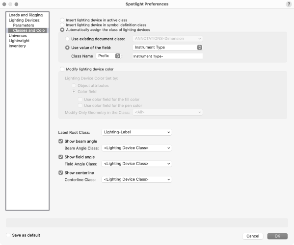
-
Now I understand better. Have you tried tabbing into the angle field of the Data Bar when drawing a Line (or wall) and pressing enter? The angle will be held until you click to complete the line.
-
The press on the T key works fine for me. Can you be more specific about what you are looking for then? Are you trying to emulate something that another CAD program has that you are missing? Are you needing to hold a snap at any angle or just the 90° X and Y axes?
-
Just a thought. If you create your front texture with a 65% grey colour as opposed to white, then if you ramp up the glow value to 250% then you might get closer to the result you are after without the bother of using an area light.
-
I’m going to file a bug report on that. I think then you will be left with creating an area light ( as @bjoerka suggested) instead of a glow texture, and use the forward texture that you have created already, but with “cast shadows” turned off.
-
I don’t think so. However, you could make two textures added to two surfaces inside the light boxes. An inner surface could contain a glow texture purely for lighting at 250%. An outer surface with a “decorative” glow texture set to 100% and not to “cast shadows”. That way you should get the best of both lighting and realism.
-
Have you tried the Smart Options display? It’s very helpful for changing tool modes.
-
Hold down the T key. That would lock the axis.
-
Quickest way to find an intersection of solids surfaces?
markdd replied to line-weight's topic in General Discussion
The Analysis tool does this in two clicks. -
Please can you all file this as a bug too. This needs to get pushed forward to be fixed for the next service pack update.
-
You are not alone. I submitted a bug last week and it is ”in the works”.
-
Convert Copy to Lines Scaling Issues
markdd replied to Sarah M Schunke's question in Troubleshooting
Try the process using an Orthogonal view instead. I am almost certain that’s the problem. -
Custom Dimension Standard as resource?
markdd replied to Bruce Kieffer's topic in General Discussion
I convert a Dimension with a Custom Standard to a Symbol. Just importing the Symbol into a new file as a Resource will import the Dimension Standard as well. It would be much more consistent if Dimension Standards were shareable resources though. -
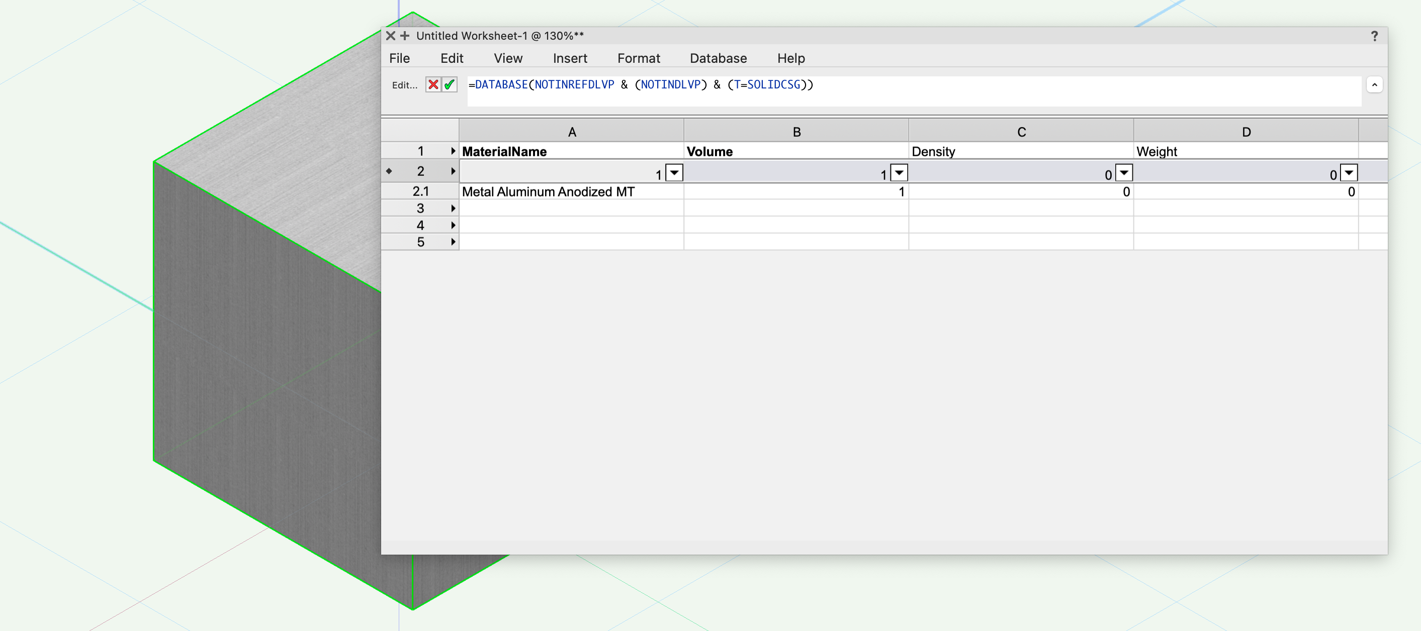
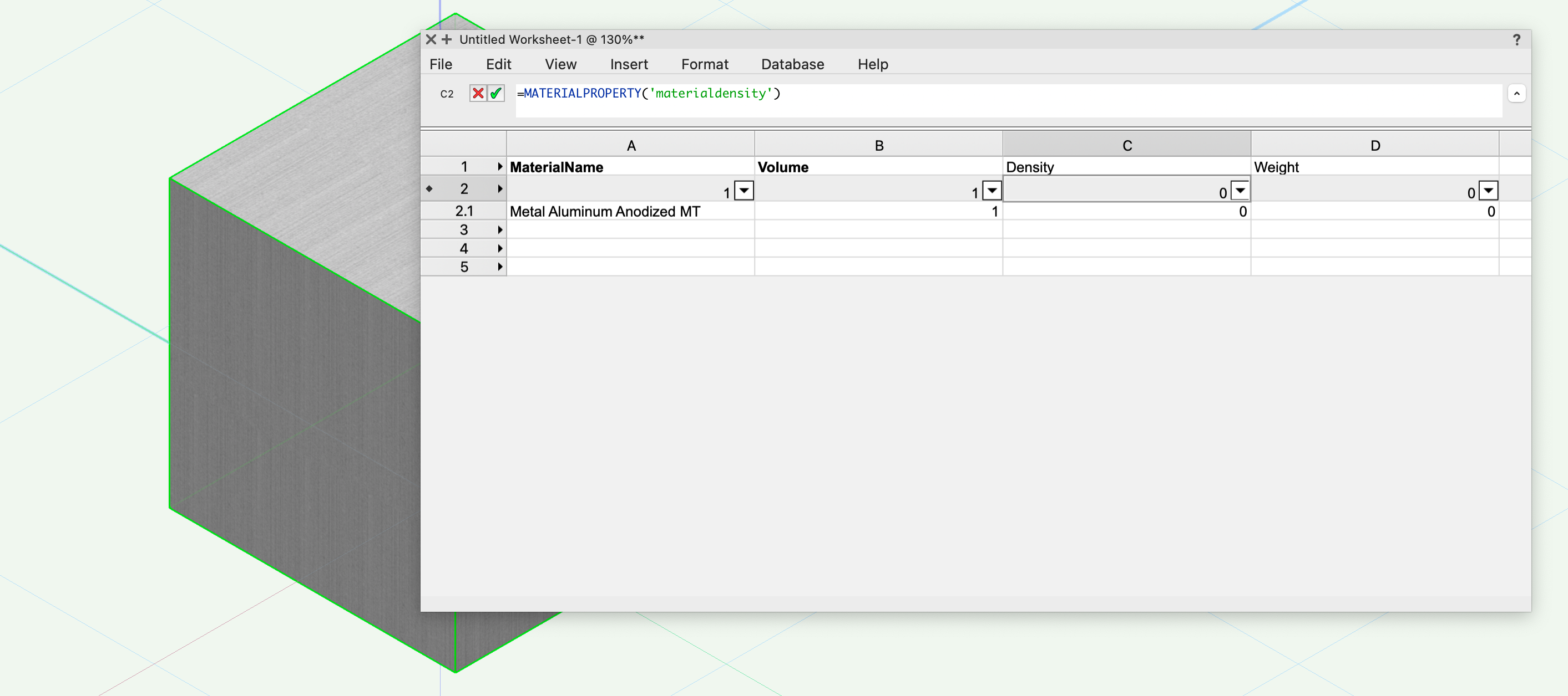
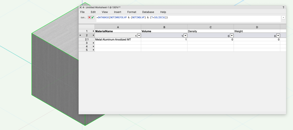
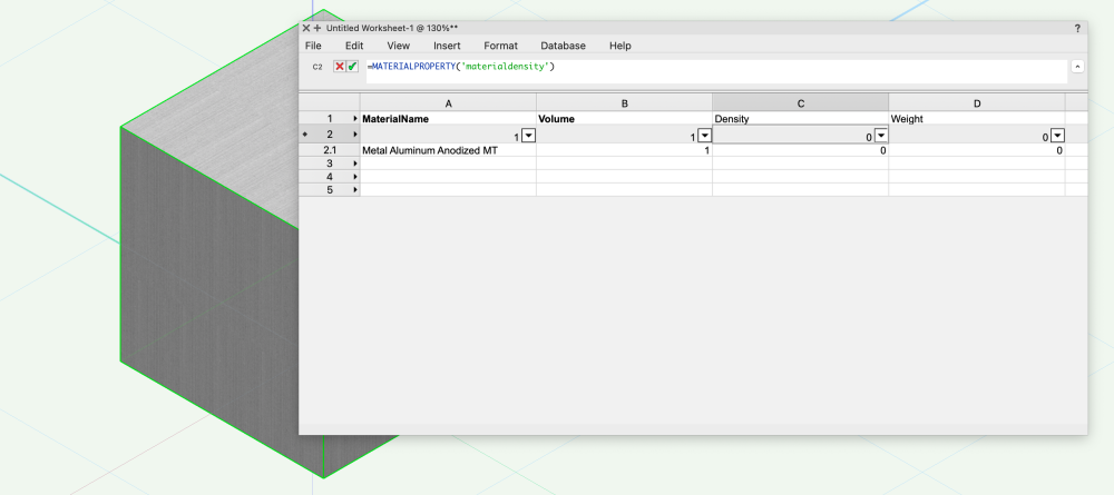
This is the way to do what I needed to do and it works well. The MaterialProperty function only works when I have the Critertia set to Material. I am sure that's what was intended by developers.
-
That's great. Many thanks Mark
-
@Pat Stanford Many thanks. My thinking was that the Material was more of an attribute and therefore I would be able to extract the Material information in the same way that you can a Fill attribute or a Texture resource. In fact, it is much more like an object or a Symbol resource.
-
I'll put in an enhancement request and see what comes back....
-
Thanks. I was afraid you were going to say that! Does that mean that material properties are not possible if the search criteria is anything other than "Type is Material"?
-
Answer to the first question is no, not that I know of. The Data Tag always uses the insertion point (if it is a symbol or plug-in). Answer to the second question is yes! In the Display Tab of the Data Tag style dialog, there is a check box for Alignto Walls/Objects. That should align the data tags correctly.
-
It would be good to see your workings. I feel sure there is something simple that I have missed.
-
Hi - Yes. Here is the file. Mass of a Cube.vwx
-
I thought I would experiment with using a Material to calculate the weight of an object. Assuming that the weight of an object is it's Volume multiplied by it's Density, then it should be possible to use the Density property of a material to get the correct answer. I have a cube that has a volume of 1 cubic meter and I am using the Metal Aluminium material. I cannot get the density to show up in the worksheet. I am sure I am doing something wrong, but don't know what! If anybody can offer some guidance I would be grateful. Enclosed is the file. Mass of a Cube.vwx Many thanks Mark
-
I suspect it has something to do with the Scale of the imported DWG geometry. Before you do anything, check with the Tape Measure tool that a known length is indeed what you think it is. If it isn't, then you will need to rescale the DWG geometry using the Scale command (Menu > Modify > Scale Objects). The "Symmetric by distance" setting sounds like what you need to use. Once all the DWG geometry is the correct size, then you should be fine. Vectorworks always draws at 1:1 so you do not need to rescale as you import. However, Vectorworks displays scale in a different way than AutoCAD and this is often an area that previous AutoCAD users slip up on at first. Come back if you need any more help.