markdd
-
Posts
3,411 -
Joined
-
Last visited
Content Type
Profiles
Forums
Events
Articles
Marionette
Store
Everything posted by markdd
-
Vectorworks Spotlight has a Video Screen tool that addresses some of what you are asking about. If you drill down into the object Info Palette you will find that it works out offset angle and percentages based on throw distance and projected image format. It's useful as a guide. You can of course make a Spotlight Instrument and project a gobo image. If you were to shutter around the screen or object you wanted to map in Open GL then it is very possible to extract the shutter image from the instrument and work out the shift ratio that way. Its longwinded and I am sure there are much better tools for mapping projection out there. Let me know if this is of interest....
-
I see the distinction now. Very good.
-
Hi all I'm struggling to understand why doing a simple solid addition to all the rails and styles, filleting the top face by ¼" and then using the split till to separate them to give the joint lines is not the simplest way to do this. I did just that and got the results shown below....

-
How to edit a referenced dwg. imported into Vectorworks 2017
markdd replied to clare weeks's question in Troubleshooting
When you import the file, you encounter this dialogue box. You are seeing a referenced viewport. To make sure that all the geometry is imported and editable make sure you uncheck the reference box. I hope that helps. Mark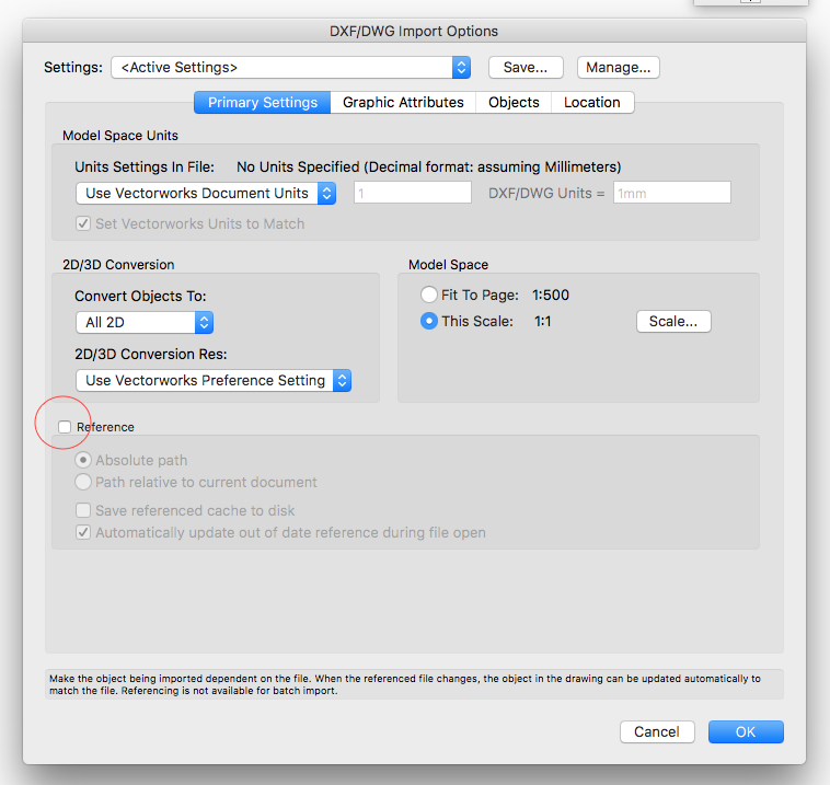
-
Or if you like them in the position they are in, then use the Split tool (scalpel) and slice off the section that protrudes through the wall.
-
Try this setting on the fillet edge (and also chamfer) tool and set the radius to ½". Then pick each timber individually. Use the shift key in the usual way to add to the selection. Mark

-
How to edit a referenced dwg. imported into Vectorworks 2017
markdd replied to clare weeks's question in Troubleshooting
As far as I remember, the reference option is there so that you can see the converted file within a viewport. You cannot edit a reference drawing. You will need to set up the Project sharing to truly share collaboratively but I think it doesn't deal with DWG's. The referenced viewport will however continuously update if the DWG changes at all. Mark -
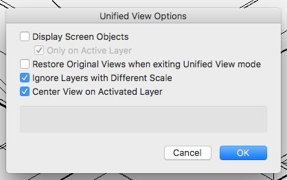
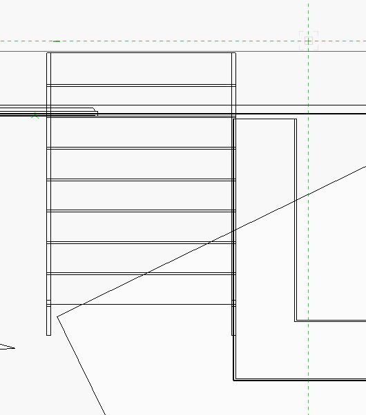
Hi It seems you have many objects duplicated across both layers. This will cause confusion when trying to understand what is going on. The first thing I did was to put the roofs into a separate class so that I could hide them. This enabled me to see much more clearly what is going on. The steps you refer to are blending into the wall because they are indeed placed so that they intersect the wall behind. An easy way to see this is to look in Top view and then it becomes obvious. Maybe try and view using wireframe more. You can see a lot more of that kind of problem with this mode. I model primarily in wireframe and constantly switch back and forth to OpenGL to check how things are looking. (Shift, cmd-G and Shift cmd-W are the shortcuts that make it really quick to do this.) If you want to model in Open GL all the time, then try using the X-Ray mode (B key pressed down will reveal the wireframe behind the OpenGL textures) This is fantastically useful. There are quite a lot of 2d objects on the drawing that are obscuring the 3d geometry. Many others here will have different approaches but I try and keep my 2d only objects on the Screen Plane so that when I am in a 3D view (anything other that Top/Plan) they disappear. You can change this setting in View Menu/Unified View Settings. I can't find the objects that relate to your earlier problem (grey pole/blue shape) Let us know if there is anything else. There will no doubt be other folk who will have loads of advice to offer you. Check out the Vectorworks Youtube channel as well.
-
Hi Are these 3d objects? If they are then how they relate to each other in terms of visibility will be based on their relative Z heights. Why not post your file, or if you prefer, then cut and paste the problem objects into a blank file that we can download? Then we make really constructive suggestions that will help you progress.
-
Also, try using the Multiple Extrude tool. Very good video tutorial below.
-
how can I rotate hybrid objects in any view other than plan view???
markdd replied to Steve Dubai's topic in Entertainment
This is definitely the way to go. Use the Create Plot and Model View command from the Spotlight Menu. Its a bit of a head scratch at first, but definitely the way to achieve accurate 2d Workshop drawings for laying out positions as well as seeing the actual structures as a model. These 2 youtube videos will help. https://youtu.be/YPVQ5nr1DDA Once you get the hang of this it really is a very useful and powerful concept. The only drawback that I have found is that the rotated positions cannot be exported to Vision. (YET!) -
"Move 3D" command - on screen axis guides
markdd replied to line-weight's question in Wishlist - Feature and Content Requests
Yes, agree with that. I like the subdivision method although I find that sometimes it is a bit unsubtle and can obscure some geometry. The translucent method used with the taper face and twist tool gets my vote. Maybe a hybrid of the two? -
What is the blue object? Very hard to tell what is going on. Could you post the file or copy and paste the objects into a new file and post that instead?
-
Could you post a screen shot to help explain?
-
"Move 3D" command - on screen axis guides
markdd replied to line-weight's question in Wishlist - Feature and Content Requests
Agreed. Would also be useful in a number of other tools such as rotate 3D and particularly when you edit symbols 2D and 3D. Mark -
In settings under General, change the size reference to: leaf size. That should do it. Mark
-
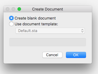
Sorry Mike, that's not the problem. It's the File/New.../Create Blank Document. That is now always imperial! Sorry if I'm being unclear.
-
Mike. It doesn't solve the Create Blank Document opening in imperial, but is a good workaround for now. I reset my preferences yesterday after some experimentation with the interactive appearance colours. and there was also a crash yesterday. I updated to the new service pack a while ago now so that seems unrelated. Many thanks
-
Thanks Mike. I understand the template concept but can't understand why when I press "Create blank document" it now opens an Imperial version where once it was Metric. Mark
-
For some reason Vectorworks opens a new blank document with imperial units where previously it was always metric. Is there a way to change it back to always opening in metric. Many thanks
-
There is this very good Knowledgebase article that may help.
-
That does the trick, thanks. Mark
-
I would like to add a custom door leaf to a door plug-in object. Where do I need to store the custom door leaves that I have made. I can navigate fine to the default content but would like to know where else the PIO can look to find custom door leaves. Many thanks
-
The door plug-in is quite extensive and will be able to build you a frame and door to most requirements that you can then convert and embellish with custom mouldings etc. If you are not clear about the actual plug-in itself then the help section is pretty good. There is not much in the way of a youtube video that I know of and I am afraid you will need to experiment alongside the help file. Other users here may be able to help further. This website http://learn.archoncad.com/about/ is a really good place to go for tips but more detailed content needs to be paid for. This Vectorworks video may help you understand the concept of the plug-in a little more but its more about how doors work with walls.
-
If you want to make a custom door and frame then it might be better to start by building what you can with the door plug-in and when you have got as far as you can, then convert it to a group. (Because the plugin object is a hybrid tool you will loose either the 2D or 3D entity depending on what view you are looking at at the time you convert. If you want both the Top/Plan and the 3D entities then copy the plugin and convert twice from each view.) Thereafter you can edit and model as you wish. It will no longer be a plug-in object but you will have the basics set out that you can add to. Convert the finished door frame to a symbol. In order for the resulting symbol to sit within a wall object you will need to edit the symbol options (right click on a symbol in a resource browser). Check the Insert in Walls option and then experiment with the dropdown menu below to get the results you require. See how it works out and come back if you need any more info.