markdd
-
Posts
3,411 -
Joined
-
Last visited
Content Type
Profiles
Forums
Events
Articles
Marionette
Store
Everything posted by markdd
-
Can you add a little more context?
-
The nearest you can use is one of the Oblique Projections from the View menu. I think the Oblique Cavalier 45 is the best for what you need. These work best in a Hidden Line View in a Viewport. Hope that helps.
-
Single Face Texture Tool still does not work
markdd replied to MGuilfoile's question in Troubleshooting
It seems to be a problem with an extrude. If the extrudes are converted to generic solids, then the tool works as it should. I'll report the bug tomorrow. -
I don’t think that this can be done. However, you could create a Viewport style with your custom scale as the only “by style” option. That would at least save you from constantly having to choose your custom scale every time.
-
For some reason, Schematic Views never inherited ALL the 2D capabilities of their parent devices. I am afraid I don't know why........ (sigh emoji!)
-
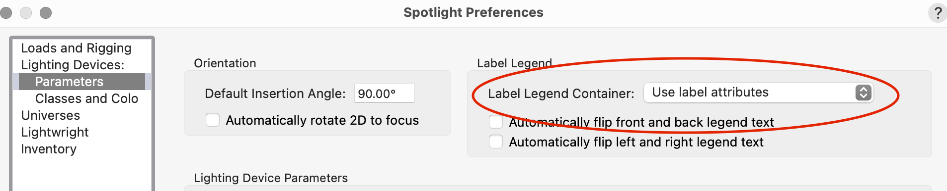
Check Spotlight Preferences. Make sure that this is not the active preference.

-
Roof objects no longer displaying blue selection handles
markdd replied to Tom W.'s question in Troubleshooting
Selection tool first mode? I have noticed that it defaults to that mode from time to time despite the fact that I never use it. -
I think the question is about the “Edit Class/Layer” buttons in the Object Information Palette of viewports. So often one needs to switch between the Edit Class/Layer dialogs to change visibilities in viewports. Currently, you need to click OK and then click on the other’s button to open the next dialog. Having an extra “Edit Class/Layers” button (perhaps next to the “preview” button) would save a click. A small wish but a helpful one.
-
Have you looked in the resource manager? The symbols should all be there.
-
Light Emitter within Lighting Instrument visible in Renderworks
markdd replied to Milo's question in Troubleshooting
They shouldn’t do that when inside lighting devices but occasionally it happens. You can get rid of them by going to the quick prefences bar and setting light objects to be only visible in wireframe or not visible at all. -
Yes please. This has been requested on and off for a long time.
-
Symbols renders are too thick and dont show properly
markdd replied to rajai's question in Troubleshooting
This is probably a scale issue. If you activate Zoom Line Thickness from Vectorworks preferences or from the button in the Quick Preferences bar (you may have to enable it there), you will probably see the result you see in the final PDF. The solution is to change your design Layer scales or your pen thicknesses. However, that is something you should do early on in the process. If you are too far down the road and have laid out your viewports already, you can scale the pen thicknesses in the viewports by selecting the Advanced button and scaling them there. Come back if you need more info.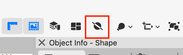
-
Managing data attached to symbols in the resource browser
markdd replied to pgreen's topic in General Discussion
I only know how to use the Records menu commands in the Tools Palette. They work best all your symbols are neatly foldered-up and you can change the values for multiple symbols at the same time. But they are still a bit of a blunt instrument and nowhere near as good as the Lighting Symbol Maintenance command which is definitely due an update. -
Working Plane view does not work correctly
markdd replied to MGuilfoile's question in Troubleshooting
Try selecting this button.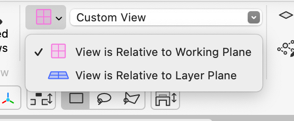
-
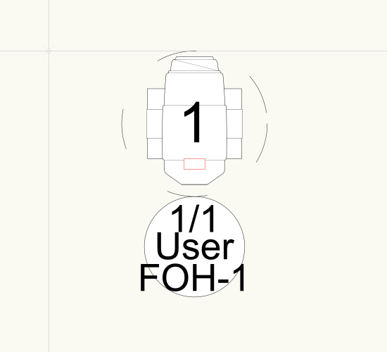
The Circle symbol in the Label Legend layout window acts as a guide only. Because it is attached to the User field, then the User Field needs to be sent to the Back using the Send Command. This will then reveal the other two fields above it. A common misconception about the Containers in the Label Legend layout is that what you do with them here will affect how they look when attached to a lighting device. It will have no effect at all. They are only there to help you space your Text Fields. Many users try to add lines and other 2D geometry to no avail. Here is your file back with the problem solved. I hope that makes sense. Label Legend.vwx
-
Can you share the Label Legend in a file and post it here?
-
Truss Worksheet to Report 2D Symbol Name Only?
markdd replied to Chris J Clarke's topic in Entertainment
Truss objects report the Symbol Name in the Object Info Palette, so the information already exists. This means that you just need to pick Truss as your search Criteria. Thereafter the columns should read =Count , ='TrussItem'.'Symbol' , ='TrussItem'.'Length' That should do it. Enclosed is the file. Truss count.vwx -
New transform mode in the selection tool in 2024 Update 4.
markdd replied to tomtomtomtom's topic in General Discussion
You can toggle it using the mode bar for the selection tool. Is that what you mean, or do you want to get rid of it completely? If that's the case, then no, I don't think so. -
Bitmap Lock Aspect Ratio
markdd replied to illumine's question in Wishlist - Feature and Content Requests
A thousand times yes! -
best way to create a shape between two polygons?
markdd replied to hollister design Studio's topic in General Discussion
Loft Surface Tool. Convert both objects to NURBS Curves using the Convert to NURBS command and then run the Loft Surface Tool in the first mode. Select the corners that most closely align to each other of each NURBS curve and then click on the checkmark in the mode bar. Select Convert to Solids from the intermediate dialog that opens and then click OK. That should do it. -
Here is a solution without redrawing.
-
Here you go! Glass Panel.vwx
-
Unable to decompose title block as a symbol in sheets
markdd replied to Camila85's question in Troubleshooting
There’s an option to do this in Vectorworks and that’s the Convert to Group command. However if you do that you will be missing all the functionality of Title Blocks which will easily do what you want and a huge amount more. Go to the help section as a start and learn how to create and use them properly. Also take a look at Vectorworks University which has some content about them. -
Automatic Fixture Renumbering for Fixture Expansion
markdd replied to Cristiano Alves's topic in Entertainment
If you use Lightwright, it is easy to do a live sync and use the +1 (or whatever value you need) function in the Lightwright spreadsheet and all the numbering will be changed on the Vectorworks light plot. @TomWhiteLight I don't think there is a way to do this using a Vectorworks Worksheet yet, but it would be great if it were added to the Enhancement list! -
Here is my explanation. I should say that the direction of the path geometry is also important. There are other ways to create the same 3D object using the Shell Tool and the Fillet Edge Tool but this should give you the techniques to complete the object you have shown in the image above.