Amy C.
-
Posts
6 -
Joined
-
Last visited
-
I have a breakout distributor object that I want to draw output lengths. I attached a Cable Distributor Record to the symbol with lengths for each output of the breakout, added the distributor of that symbol, but when I click the draw output lengths box in the OIP nothing happens. Is this a bug or is there another way I need to specify the lengths of my outputs to see them?
-
Thanks Justin! I think I might have solved it but I just sent you the file in a DM to look over and confirm.
-
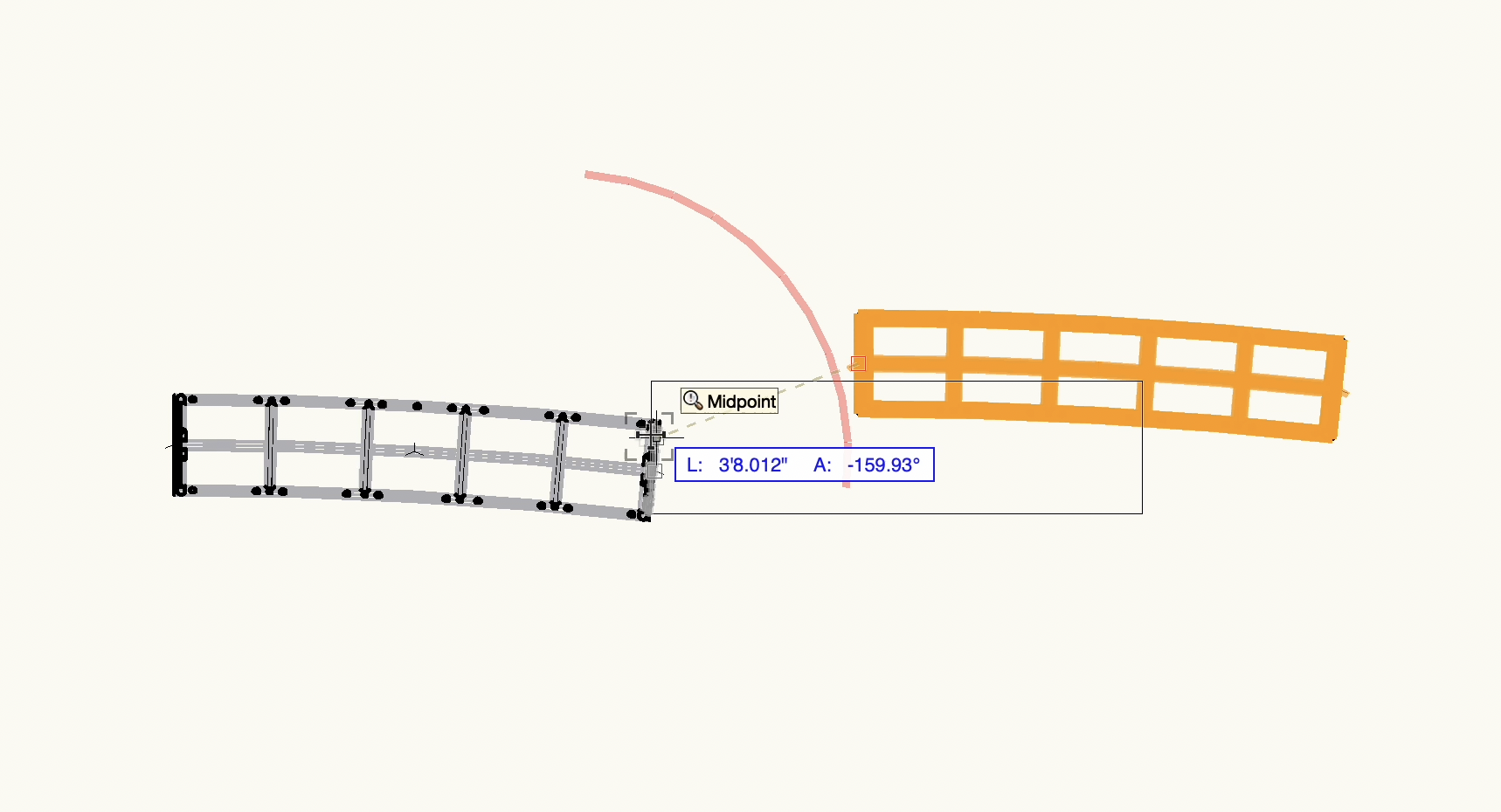
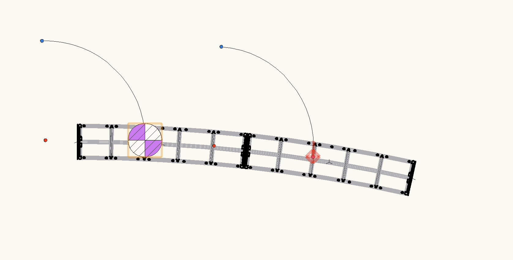
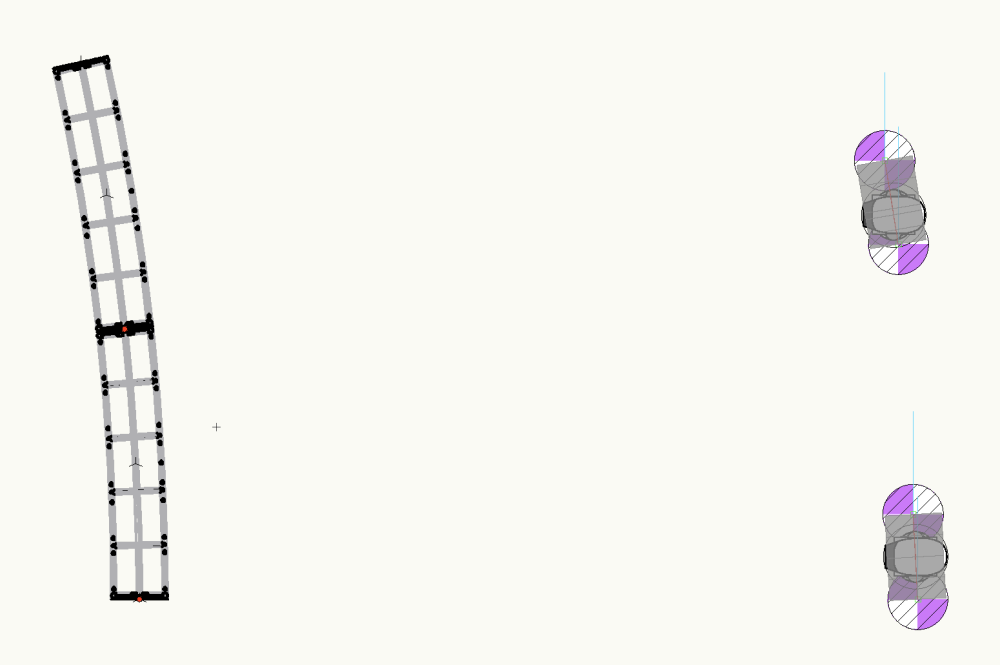
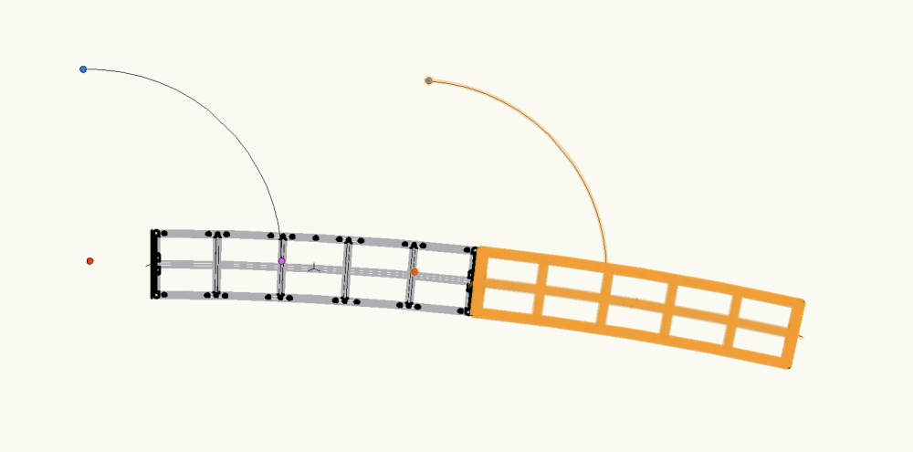
If I put the motors and a load on the centerline then it calculates and says everything is connected properly, it I put them on the truss itself even where it shows snap points on the centerline it won't. But the centerline is way off the truss symbol even with the truss symbol starting at 0,0,0. No matter what numbers I put in for the diameter and angle the centerline is always off the truss. The larger the diameter the further away from the truss and longer the line. With a very small diameter and angle it is close to the truss but I can't get it to be both on the truss and the right angle/length of the truss.
-
Thanks for your reply, I updated my symbol positioning to reflect what you showed, I was centered on the zeros. My actual angle is 6.25 per truss, in the screenshot above the angle is much higher. I've been trying to get the centerline on the truss and still can't. When I put the 6.25 angle and the diameter change of the truss the centerline is 3' right of the truss and the centerline is a few inches long. When I put the diameter as length to the center of the circle given that angle the centerline is the length of a single truss but is over 50' away from my truss. And it still isn't actually connecting as a system.
-
Some screenshots showing what I mean. First the connection line not matching the truss, second the centerline not following the truss, third the only connection point for motors or loads, but even when attached there I get a not properly supported error. Some


-
Amy C. joined the community
-
Hello, I'm trying to make a custom curved truss, I have a DWG from the manufacture that I've used to make a symbol. I added 3D locus on the edges and middle of the truss and magnets to the edges, then used the convert to truss command. I entered the truss properties, and updated the magnets again to confirm positioning, and refresh the magnets. When I try to snap trusses together, the red line goes perpendicular to the other truss, and though they look snapped together they aren't connected (when I select system objects it selects nothing else). When I turn on centerline the centerlines are the perpendicular direction. I tried rotating my symbol and it doesn't fix the issue. Also, I can only attach motors or fixtures at one point on the truss, but then when I try to run any Braceworks calculations I get errors that the loads are not attached and truss not properly supported, even if I connect them at the one point. Am I missing something for getting these custom curved trusses to connect as a system? How can I attach motors or loads at any point along the curved truss? Thanks for your help.