


Ramon PG
-
Posts
900 -
Joined
-
Last visited
Content Type
Profiles
Forums
Events
Articles
Marionette
Store
Posts posted by Ramon PG
-
-
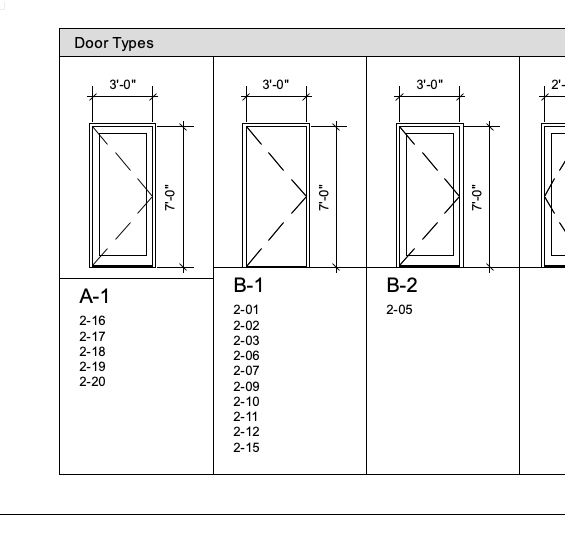
Door Type A-1 comes in 8-0, 7-6 and 7-0 heights. Why only one shows and how can I fix that? Thanks
-
5 hours ago, Raph said:
Hello,
Thanks for the feedback but I'm not sure I understand...The symbol exists, I just call it up and place it on the drawing.
The problem is that I can place it in 2D (X,Y axis) but not on the Z axis
If it is a 3D object you can decide it’s height AFF during its creation. (Drinking fountains, sinks, luminaires, etc). 2D symbols I’m not sure, but you certainly can move them in space up of down after you insert them in a drawing like another poster suggested.
-
Love data tags, but there’s a need to uniform how one works with them to get the auto-numbering benefit.
-
2 hours ago, Raph said:
Hello,
I'm creating a scrip that calculates and places symbols according to a precise scheme.The idea is to draw a frame with symbols that already exist.
With the function:
vs.Symbol(symbolName, p, rotationAngle)
I can place the symbol at 0 on the Z axis
I'd like to be able to place or translate the symbol, for example, 2 meters away with the opposite side down.
Any ideas on how to do this?the parametric symbol is on the left what I'd like to achieve is on the right
Thanks in advance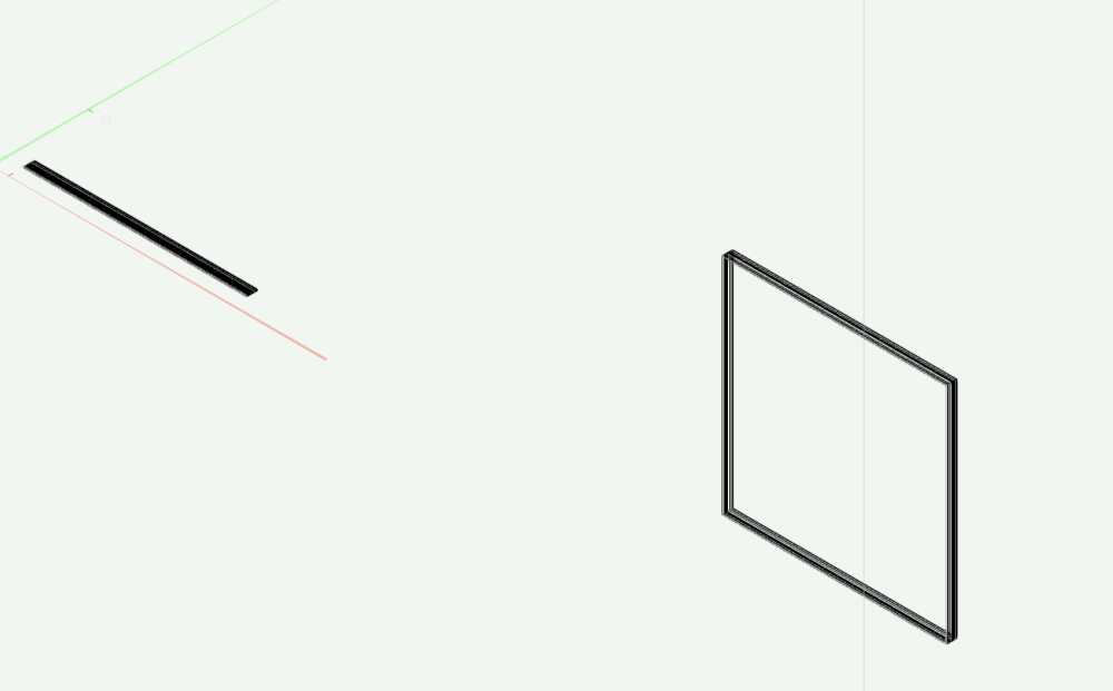
You can better during symbol creation raise it to the final AFF level you wish and it will insert accordingly.
-
-
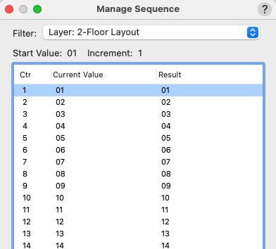
Finally figured out. It had to do the the Manage Sequence Filter. You have to be careful that only the appropriate layer is selected. I had not selected the 2-Floor Layout and the numbering was operating on 1-Floor Layer also and you cannot have two doors with the same "Value", eg. 1-1 and 2-1 is not possible w/o the proper filter.
-
1 hour ago, Tom W. said:
In what way will it 'not accept' setting the ID fields to be by instance? There is nothing untoward in your screenshot.
Thanks for the reply.
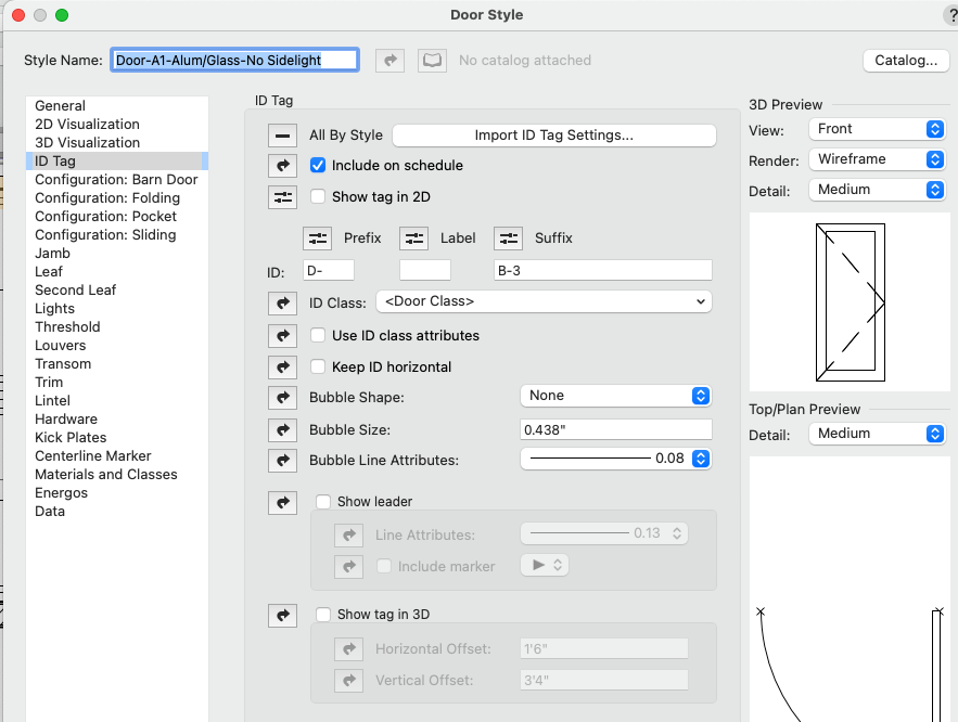
The door should be 1-01 but entering the 01 in the ID Label box or the Door Schedule Worksheet will not work and the door number reverts to 03.

-
Hello, I have a styled door that will not accept "by instance" numbering (ID label).
Why???
-
That small improvement can save lots of headaches bc all the other worksheets will update before printing final construction documents, but not that one.
Thanks for the reply.
-
 1
1
-
-
10 minutes ago, Kevin Shertz said:
Hi Ramon, can you clarify what you mean when you say the current one is "not reliable?"
Room Finish improvements are on our feature roadmap, so any thoughts/opinions you'd like to share would be very helpful to the team.
Thanks in advance for any input you'd like to provide.
Thanks for the reply and sorry for the confusion.
The "old one" (from Create Rm Finish Legend menu) does pick up legend items when placed in the drawing, but only the first time.
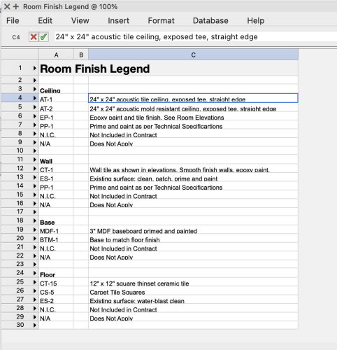
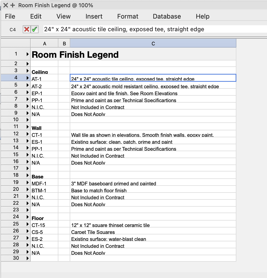
As to suggestions... Can it be automated so that it reads the "keys" and descriptions from the Finish Schedule? Sometimes changes are made to the Room Finish Schedule and the Legend will not pick it up even if you use the "Recalculate" button because it is a Worksheet Image, I suppose.
-
How do you make yours? The old one is not reliable.
Can it be automated so that it reads the "keys" from the Finish Schedule?
Or do you use the Graphic Legends?
-
15 hours ago, Josh Loy said:
Are snaps enabled for other layers and classes?
Thanks to all for the replies... finally found it!!!
Not senile yet, but getting there. I don't remember turning it off.
-
1
-
-
Hi, I'm on 13.5
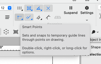
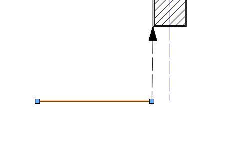
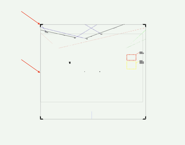
I'm a bit lost. What I'm trying to do is lock the snap to a distant corner.
-
Now when I approach a snappable object I get no hints.
-
On 12/15/2023 at 4:42 PM, Pat Stanford said:
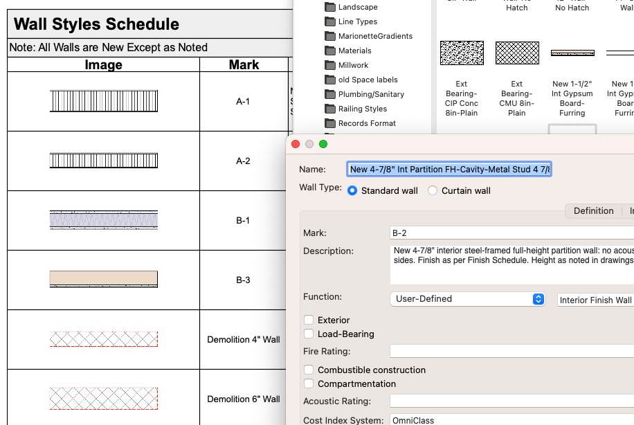
Is B2 actually applied to a wall that is placed in the drawing?
Is there something about the criteria of the Graphical Legend (Layer or class excluded?) that is preventing it from showing in the legend?
Yes, the walls are placed in the drawing. Found the fix.
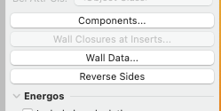
Now, for the confusing part... Seems you can have different wall data for the same wall. The styled wall said "Mark: B-2", But clicking the the Wall Data button (see below) said "Mark: Existing 6" CMU". Why VWs chooses one over the other is a mystery to me. Why would you want these entries to be different for the same wall is also a mystery to me.
-
12 minutes ago, rDesign said:
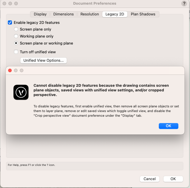
Thanks. Don't remember what I did to get into this. A few days ago I didn't have the crop view.
-
-
Must be my alzheimers... I swear I could get rid of this crop thing in model perspective view, but can't find the Preference.
-
On 12/14/2023 at 5:34 AM, Theo D said:
Hello everyone,
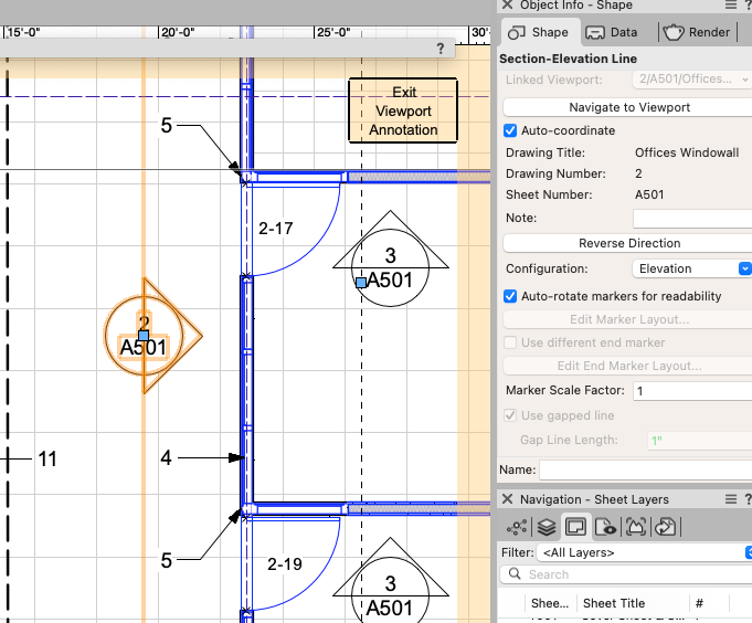
When I make a section or an elevation with the clip cube to send as a viewport in a presentation board and I make dimensions of my section or elevation directly in my drawing layer, the dimensions don't appear in the viewport and I end up having to dimension my sections or elevations directly in the viewport.
Is there a solution?
Thanks for your help!
Your VP might not have the Dimensions class active. I agree you should place them in Annotations. -
6 minutes ago, Tom W. said:
I would either:
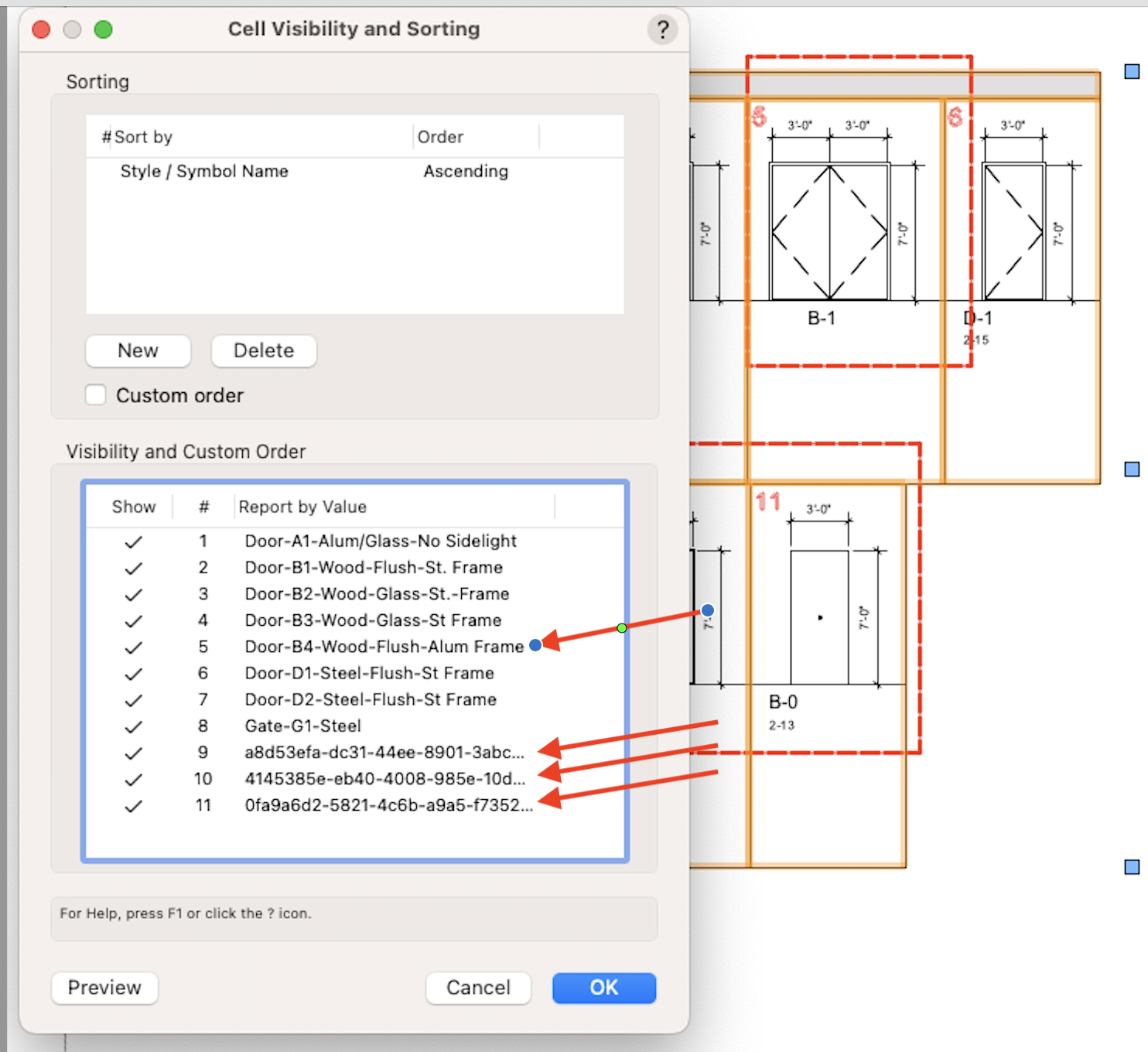
- Create a quick report then find the mystery Door that way.
- Use Custom Selection to find the Door.
- In the criteria for the Graphic Legend include 'Field Value On Schedule is True' then it will return only Doors which have 'Include on schedule' enabled.
But that Door must exist somewhere in the drawing for the GL to be finding it.
Presumably this means you've got Doors in the drawing with duplicate IDs - so you need to find them + renumber them or delete them or whatever no? The Graphic Legend will just search for whatever you tell it to look for.
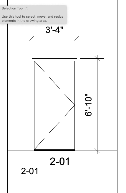
Don't really understand what you're saying: all the Doors in the GL are measuring 7 foot high not 6 foot 8...?
Thanks again for the reply
Sorry about the last item confusion, I edited the styled door dimension as I commented and the GL then showed it.
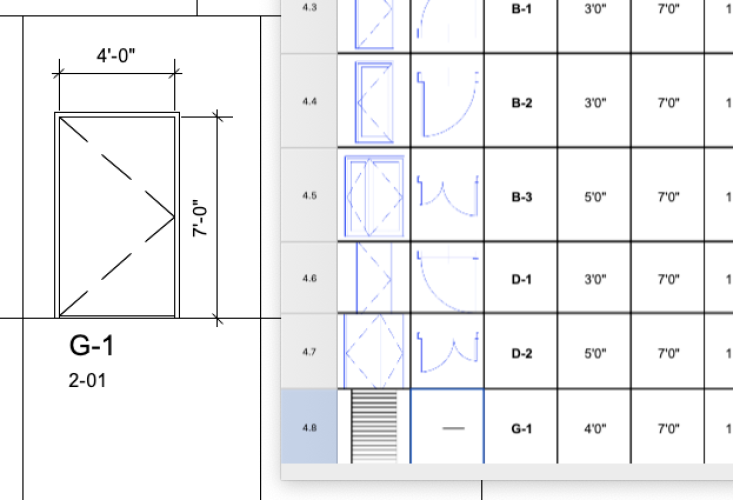
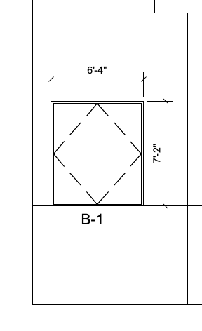
Also... the GL will not show the symbol geometry as the worksheet will? Another puzzle. (4'x7' door)
Below... found how to delete the phantom doors from the GL. As to where are they in the drawing, that's another matter.

-
On 11/28/2023 at 1:02 PM, Tom W. said:
In the 'Define Legend Image' dialog set the vertical + horizontal dims to 'Leaf/Sash'.
Don't understand the question
Thanks for the reply.
First item: fixed.
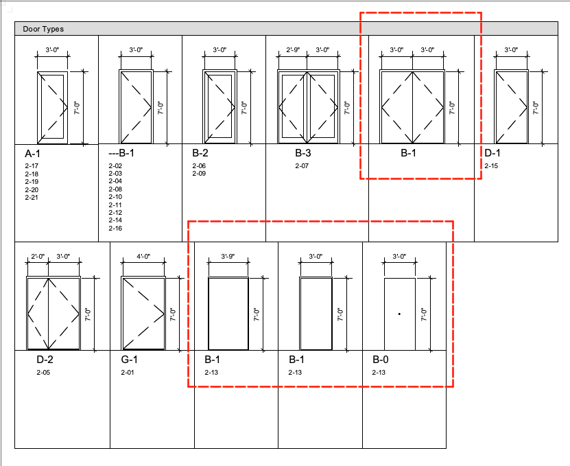
Second item... the B1 door has no number so I cannot find it in the drawings with a right-click like we can in the Worksheets. I don't have any 6'0' solid leaf doors.
Also... 3 doors with the same door number.
Also... adding to my confusion the Graphic Legend shows the 6'8" door height of the Door Style regardless of the edited door height of some items which is 7'0" and appears as such in the Door Worksheet. So one needs a different style for different door heights?
Conclusion: The Door Graphic Legend does not seem very practical for me.
-
How can I get the Graphic Legend to measure only the doors, not the opening?
How can I find the B-1 door that has no number?
Thanks
-
On 11/22/2023 at 4:35 PM, zoomer said:
First, I always postulate that BIM CADs need to separate
Structure from Finish.
You may likely have 10-20 Finishes and 10-15 Structure Styles.
But in all needed combinations that does no more make sense.
OK that needs also intelligent PIO Insertions like Windows and Doors
that are able to cut into more than a single Wall.
If the Finishes are defined by Space settings and or outer/inner
building element state - don't know.
My other CAD at least allows to manually assign cutting elements to
also cut other objects. And for Styles, it has an option for a variable
thickness for one of the components.
(Like the same concrete Slab package that uses multiple thicknesses
for the structural Slab, according to bearing needs)
This saves a lot of Styles or their similar duplicates.
As we are in VW ....
As long as it makes sense I do have Style Duplicates.
Exceeding that, I may start searching for some workarounds.
I would agree that room finishes should be inked to walls in the room.
-
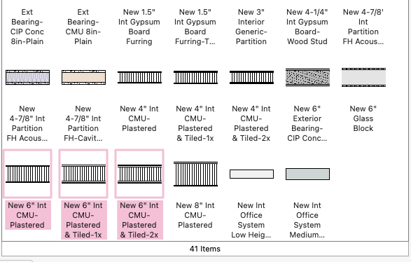
I have new 6" plastered CMU walls that are plain, tile finished on 1 side and on 2 sides.
Question: Do you have 3 wall styles? Or do you have 1 style and turn on or off the tile finish?


Not able to access product updates
in General Discussion
Posted
Seems my organization's server is blocking this. What is the website so that I can fix this with my IT people?