


SamIWas
-
Posts
409 -
Joined
-
Last visited
Content Type
Profiles
Forums
Events
Articles
Marionette
Store
Everything posted by SamIWas
-
I haven't created one, but it should be fairly easy to do, depending on how much detail is desired. Just a flat with basic framing? Not hard. Adding all the hardware and braces? A little harder. Adding a stand? Even harder.
-
My idea was to be able to move them up or down by a certain distance. Indeed...I decided it wasn't worth the time since it involved parsing a multi-line text string. I did start using "copy altered label legends" for now. My only issue is that it doesn't appear to work on 3D legends. I have not yet looked through the code needed to work on those. I do like how yours is able to select the source fixture after running the script. That's a thing I need to learn how to do. Guilty!
-
Thanks! I've seen that one. Had a little different idea in mind. I've figured out where the label positions are stored, but they're in a long text string and not separate fields, so now I need to look at how I can manipulate that text string effectively.
-
I assume that the Control Points for label legends are buried inside the Lighting Device or some other record somewhere, and thus able to be manipulated. I have found 8 control points which I am able to pull into a worksheet and view, but they don't appear to have anything to do with label legend field locations. Does anyone know if there's a syntax which would allow a script to move a certain label point for a range of selected fixtures?
-
New grouped label-legend feature not working correctly?
SamIWas posted a question in Troubleshooting
I just started in 2019, and stumbled across the feature with the ability to group fields in label legends, which is amazing. I've been wanting this forever, especially with the ability to add text such as a universe/address divider. And, they behave nicely with the "adjust flipped text" option. However, the grouped fields do not appear to behave as expected as par as position goes. Looking at the attached image, you'll see that the ungrouped fields move as expected to hug the bottom of the fixture (but don't work right when flipped). The grouped one flips text as desired, but stays in the same location relative to center no matter how big the fixture is. I assume this is not how it should function. It would also be great if the group could auto-center so that the label was always centered on the center point of the group, no matter how wide it becomes. For instance, if your universe is 4, the group will be a different width than if it's 24, and the label will be slightly offset. This is far less important than the position. Hopefully, this can be fixed in the next service pack. I'm thinking I'll deal with the position for now.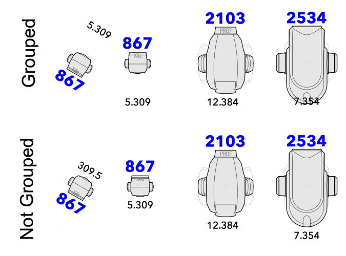
-
You can do this in a worksheet. Make a worksheet with whatever info you need to figure out which fixture it is, along with a column for purpose, and edit the info in there.
-
Apologies if this has already been asked or solved. My crappy internet is preventing much searching in a reasonable time. If I am editing one object in the OIP, then I try to select another object in the main drawing window, I am now required to first click in the window, then select the object. Simply clicking on the object once does nothing. I am still on SP3, so maybe that's part of the issue. Whatever it is, it's killing me and causing accidental data entry when I think I've selected a different object. It has not been this way prior, as this is a major part of my workflow. Has this been figured out?
-
I have some PIOs in which I'd like to be able to put any symbol name into a field and have it displayed. That is easy and have that working. Is there a particular way to get the PIO to display only the 3D parts of said symbol when in 3D views, but use the PIOs definition when in 2D views? In other words, I may not want to see the 2D part of the symbol in Top/Plan view, but just whatever the PIO itself draws.
-
Very simple: .tab files allowed for text import
SamIWas replied to SamIWas's question in Wishlist - Feature and Content Requests
This is an option, and what I will likely end up resorting to. Just a pain to have to script around a simple file extension. -
Very simple: .tab files allowed for text import
SamIWas replied to SamIWas's question in Wishlist - Feature and Content Requests
Yes...this is what I currently do. I navigate to the folder in question and give the file a new extension each time (it's usually only one file at a time, but I do use Better Rename if it's a bunch). That is cumbersome, especially when having to do it multiple times per day (or in the case of testing scripts, multiple times per hour). Since Filemaker refuses to acknowledge such an issue, I am hoping that the more involved and helpful folks at VW can look into it! -
I use Filemaker. A lot. For everything. A few years ago, they changed something in their code which made it so you could not save exported data as a .txt file. It has to be .tab. Then you have to navigate to the file and change it manually to .txt. Vectorworks does not allow the choice of .tab files at file selection during script imports. I and others have tried for years to get Filemaker to fix the export file choice. But, being that they are owned by Apple now, admitting any kind of fault in the product and fixing anything based on customer request is unheard of. So, maybe Vectorworks (much more accepting of customer input) can make the change on their end? Possible to allow the choice of .tab (tab-separated text) files?
-
If you're referring to lighting and basic rendering upgrades, then agreed. Vectorworks could certainly benefit from Cinema's lighting options. A single Cinema light has upwards of 90 options. I thought you meant that Vectorworks should have "all the things" that a full 3D modeling program would have.
-
I'm not sure I necessarily agree. At some point, the program becomes too bloated from it's true purpose. At what point does it go from beefy CAD program to full 3D animation program? Then, people will want all the features of full 3D animation, which is a massive set of features. Not to say that VW couldn't use a lot of work on a lot of features. I'd love to see Cinema's level of texturing, lighting, true 3D coordinate system. But, I'm in the camp of letting complimentary programs do their strength and work with each other. At this point, it's almost like we just need Cinema to have some of VW's tools...then we'd have everything we need!
-
Thanks everyone for making me think. I got it all working. The original problem was not drawing on the "ground". That as fixed by either using 3D polys, or using the 1160 variable. Then, I couldn't get the polys to go away. That was fixed with the DelObject calls, which for some strange reason, I missed.
-
No issues with the Extrude Along Path tool itself. It's when I run it through Vectorscript that I can't seem to make the original shapes disappear.
-
I couldn't figure out how to make that one work at all. I have managed to get the strange rotation issues dealt with by using 3D polys as the path and profile instead of rectangles. But I still can't get them to go away once the extrude is made. I'm left with the extrude and floating polygons.
-
I am trying to do a very simple extrude along path in Vectorscript to basically make a square or circle tube box. When drawing, I simply create a rectangle for the path, a rectangle or circle for the profile, and run "Extrude Along Path". I have managed to get Vectorscript to make the object, but I'm running into a few problems: 1. It seems to draw these things on screen plane rather than using basic world coordinates. I tried setting the plane, but that didn't appear to do anything. 2. It leaves the 2D objects there. This is a test section of code. It should create an 80x80 box of 2" square tube. It does, but it is always perpendicular to the camera, and not flat on "ground level". I tried using "SetWorkingPlace". I know I'm doing something wrong, or leaving something out. Any leads? Rect(-40,40,40,-40); struc1:=ConvertToNURBS(LNewObj,FALSE); Rect(-1,1,1,-1); struc2:= LNewObj; struct:=ExtrudeAlongPath(struc1,struc2); Move3DObj(struct,0,0,10);
-
No. I believe what Cinema does is just save the object as two splines, their location, and the location of the sweep. So, instead of saving a crapload of polygon info, it's just saving the poly line definitions, which is just a few numbers, and the locations, which is just some coordinates. It's a tiny snippet of text. As far as the more complex geometry, I'm assuming it just has a different method of storing the definitions. The 1Mb file size for the symbols sounds much more reasonable. For me, the main issue is transfer and storage. It's pretty much impossible to email a VW file. You have to go through web transfer of some sort, which is a pain. Some of our Dropbox folders are multiple gigabytes (one show is 35GB), which just chews up hard drive space when you are linked to multiple shows. I have a 6-year old iMac that I run on at home, and it is also quite stable.
-
Man, that's just wrong. A file with 100 simple sweep objects taking nearly 50MB of space? Just tried it in Cinema with 1000 4x4 sweeps with 1˚ increment and 1˚ detail on the rounded profile. 3.2 MB file. I've always thought the file sizes of VWX files were a little ridiculous. That sounds like an engineering issue to get such a huge file size with 100 simple sweeps.
-
Should parametric 3-D parts take much space at all? A sweep should take very, very little space. It's two poly lines to the program, and the file shouldn't have to store the actual 3D info. But, VW may not function that way and may save the full 3D information. Cinema 4D is much, much better at managing file size. Even my biggest projects with tons of high-poly sculpted 3-D objects are well under 200MB. I have some where an entire museum gallery model including a sculpted sand floor, a lighting grid, a ramped glass deck, and a dozen sculpted poly objects has a file size of 10.5 MB. Another is an entire museum exhibit...every wall, case, scenic object, pipe, and lighting fixture, for a 10,000 square foot exhibit...total file size is 45MB. Contrast that with my current smallest soundstage with a simple mid-size apartment set, a tiny room set, and a few lights...file size 155MB. I do have a lot of lighting symbols and some textures files, but still...
-
VS Access to the user created fields in the Lighting Device
SamIWas replied to Sam Jones's topic in Vectorscript
I have dozens of scripts that do exactly this on my 20 or so user-created Lighting Device fields. I don't recall not seeing changes in the OIP, but maybe that's true. I did have to add a ResetObject to get the data to change on screen. -
Top/plan panning/zooming sluggish in VW2018
SamIWas replied to line-weight's question in Known Issues
I have had constant issues with laggy pan and zoom on my top-spec MacBook Pro, even with all settings to use the best graphics. With the same file on Vectorworks viewer on a cheap MacBook, a co-worker had extremely smooth zooming. -
Prefix to label legends (# before channel number)
SamIWas replied to Cookie_NZ's topic in Entertainment
The container solution is exactly how I do DMX addresses, because it's the only real way to deal with it. An alternative, but error-prone way of dealing with it, is to use a user field for your display info. I really want VW, or at least spotlight, to have an "auto calculation" parameter type where it could auto-create certain field styles based on a combination of other field info. I use this extensively in Filemaker. For instance, when I have a Universe and Address field, I have a separate field which auto calculates to the universe, a dot, and then the address in three-digit mode (Universe 6, address 37 calculates as 6.037), for paperwork. This would be invaluable for things like circuit name and number, so that circuit 2A 5 doesn't become 5 2A when you rotate your symbol. -
Not still the case. I have a class with 36 characters, including spaces and dashes.
-
I programmed Vectorscript for ten years before I finally delved into creating custom plugins. I don't know why it took me so long. If you can write Vectorscript, it's pretty simple to create a custom plugin. I've now created numerous tools for cabling, networking, racks, and others. I did it for the same reason you are looking for: to have the info on the shape panel instead of the data panel. And because with a plugin, you can do drop-down menus, checkboxes, enter actual dimensions, hide parameters based on others, etc. So much more versatile than data.

