


SamIWas
-
Posts
409 -
Joined
-
Last visited
Content Type
Profiles
Forums
Events
Articles
Marionette
Store
Posts posted by SamIWas
-
-
12 hours ago, Andy Broomell said:
I've had issues with using the "Image" function for shader. Have you tried using "Image Mask" instead?
I just tried the image mask after your recommendation, and it renders the same in Renderworks, but completely disappears in Shaded View.
I should mention that I'm on 2022. I wonder if 2023 fixes this. Not likely....
-
Forgive me if this has already been discussed...couldn't find it with a quick search...
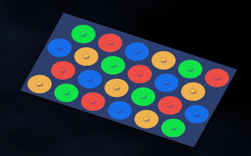
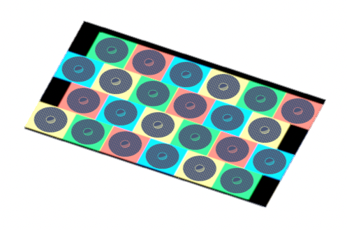
I am working on some textures with transparency using image files. They look great when in Renderworks. But in Shaded rendering, the transparency is reversed and looks awful.
These are two extrudes, one with the color info and glow, and the other with the transparent circles and pattern. The transparent one is slightly above the color one.
Anything I'm missing here?
-
On 1/4/2023 at 1:56 AM, Pat Stanford said:
It is a lighting device problem, so I am going to leave it to the Spotlight experts to try and figure this one out.
If I place a copy of the symbol on the same layer as the lighting device using the symbol, the LD renders with square knobs. The symbol with round nobs.
Even after replacing the symbol the LD is using and then switching it back.
Very strange.
Things get even stranger with regards to lighting device rendering. Now I've found that even if I have an object assigned to a certain class which has a texture assigned to the class, an object within a lighting device will render with that texture even if the texture is assigned to "None" for that particular object. The object will not take on the object color. If I insert the symbol as a symbol, and not a lighting device, this does not happen. Ugh...so frustrating. Have to make the texture take on object color to get around it.
Same symbol as a symbol and a lighting device (with random test block added)

-
8 minutes ago, Jesse Cogswell said:
I have also found that this only affects design layers, if you have a viewport set to Shaded background render mode, everything renders as it should.
Well, good to know that viewports render correctly, since that's what most people will see.
-
1 hour ago, markdd said:
I know this probably won’t help you now, but I opened the file in 2023 and all is fine.
Have you tried converting any sweeps and other problematic objects into Generic solids?
No, I have not converted them. At this point in building, I still want to be able to edit the shapes.
-
3 hours ago, Pat Stanford said:
What happens if you copy and paste the fixture into a new document? If that has problems, please post that file so we can take a look.
If that does not have problems, can you post the original file?
The problem has persisted, so I made a new file to test it out. The problem followed to a new file. I have attached that new file. In the file, there are pasted examples of the renders and some notes.
In my preferences, 2d and 3d conversion are set to high. Any other setting related to display is on at least high.
-
2 hours ago, Pat Stanford said:
What happens if you copy and paste the fixture into a new document? If that has problems, please post that file so we can take a look.
If that does not have problems, can you post the original file?
I didn't notice issues in other files, but I've been working mostly in that single file recently. Let me see what happens now that I've changed the 3D Conversion Resolution. If it continues, I will post the file. I've already completed the fixture in the pasted image and moved on.
-
15 minutes ago, Pat Stanford said:
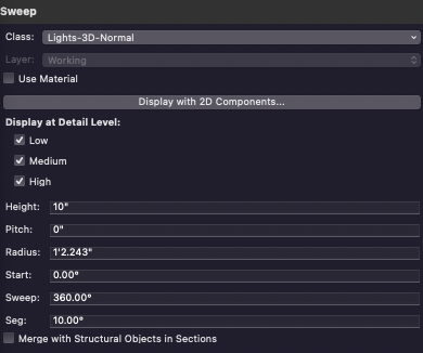
Check the VW preferences and make sure the 2D and 3D Conversion Resolution are not set to Low. But even that should give an octagon and not a square.
The 3D Conversion resolution had been set to very high, which I think I read can cause issues. Let's see if that solves it. Thank you!
-
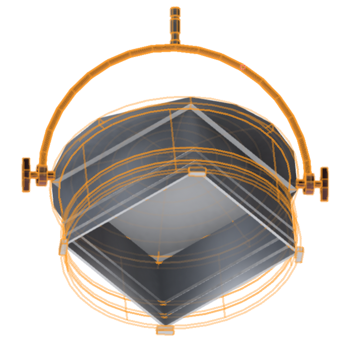
I've been having this issue recently where sweeps render in Shaded view as squares or diamonds. In the posted image, you can see that it is a round object, but it's rendering as square. Shaded view is in High Detail mode. If I change the detail mode to anything else, it updates, and renders correctly. But this is nearly all the time now. I have noticed this only in this particular file, but haven't done enough experimenting to see if it happens elsewhere. Is there some dumb setting somewhere that might be causing this? This tracks through restarts of Vectorworks and my laptop. VW 2022 SP3 on MacBook Pro.
-
2 hours ago, Pat Stanford said:
Post the script and we can help you get it working.
Ha...good idea. This is probably terrible code. Not being really familiar with function calls, it's probably not written right at all. Well, obviously it's not because it doesn't work! 😄
The general idea is that I select a piece of text inside a symbol, and the script changes that text to the correct font and correct justification, then changes it to a poly line and applies the correct attributes.
PROCEDURE Convert; VAR h,hp,ht : HANDLE; ti : LONGINT; FUNCTION GetTextBlock(h:HANDLE):HANDLE; BEGIN Locus(0,0); h:=LNewObj; ht:=PrevObj(h); SelectObj(ht); DelObject(h); END; {gettextblock} BEGIN ht:=GetTextBlock(h); {----change font attributes of existing text----} SetTextVertAlignN(ht,3); SetTextJustN(ht,2); SetTextFont(ht,0,20,GetFontID('Avenir Next Medium')); ti:=TrueTypetoPoly(ht,hp); {----Set class and attributes of new group----} SetClass(hp,'Lighting-Label-Degree#'); SetFPat(hp,1); SetFillColorByClass(hp); SetLSN(hp,0); END; Run(Convert); -
On 12/9/2022 at 2:21 AM, MullinRJ said:
Have you ever heard of WALDO?
No, you are not missing anything in the VS API. There is no command to get a handle to any object when you are inside a container object (SymDef, Group, Sweep, etc.)
But there is WALDO. He's very useful when you want to run a script and you are editing inside a container object.
WALDO works like this:
1) Drop a 2D Locus anywhere – (0,0) is as good a place as any.
2) Get a handle to the Locus with H := LNewObj;
3a) Get a handle to the previous object with H1 := PrevObj(H), or H1 := PrevSObj(H). Now you are at the top of the stacking order.
or
3b) Move the Locus all the way to the back and get a handle to the next object with H1 := NextObj(H) or H1 := NextSObj(H). Now you are at the bottom of the stacking order.
4) Delete the Locus with DelObject(H).
WALDO (if you make it a function) returns H1. Your scripts can now run INSIDE container objects if you use WALDO instead of FActLayer, or FSActLayer, or LActLayer, or LSActLayer. Waldo works on Design Layers, too, so you don't have to worry about where you are when you run a script.
Welcome to Waldo World,
Raymond
I kind of get what you're saying, but can't for the life of me get it to work. I'm sure there's some stickler in the call to the function. I know the function runs because it drops the locus. But nothing happens past that. The locus won't delete, either. So it seems that the handles aren't being assigned. I'm just going to keep doing this manually for now. Spending more time trying to get the script to work than just manually doing the actions!
-
Is it literally just a grid of squares? Can you enter your info via the OIP, or does it have to be by dialog? Because if it's just a grid of X x Y squares of A x B size with C padding, and the info can entered in the OIP, this seems overly complicated.
-
I can't believe I've never run into this before...
Write a small script to change text to poly line, then apply the correct attributes, because I'm doing it hundreds of times through a ton of symbols. Finally got everything working correctly, then went to do it inside the symbol definition, and it does nothing. FSActLayer doesn't seem to work inside symbols. FSObject doesn't seem to work because it still has to reference a layer. FInSymDef doesn't appear to apply to current selection Is there another one I'm missing here?
-
On 12/4/2022 at 12:44 PM, JBenghiat said:
I think your experience is a red herring. You do not need to have an object at the control point, and there isn’t even a mechanism to “assign” and object to a control point.
Also...@Pat Stanford
You are correct. It was a red herring. What I have found is that if your control point defaults to 0/0, and you have nothing but a 2D locus for the 2D portion (I haven't started building the 2d yet), you cannot move the control point. Once I added just a rectangle, I had control of it. If I remove the rectangle, I again cannot select and move the control point. That's fine, I plan on having 2D stuff drawn.
-
I am working on a PIO which contains a control point. I added it just as I have in other PIOs. However, in this PIO, I am unable to move the control point using the cursor. The cursor does not change to the little arrows when I hover over the control point, and I cannot select it and move it. It does in another PIO I wrote. I cannot figure out why. Any ideas?
EDIT: Figured this out, but thought I'd leave this up in case anyone ever searches. You apparently have to have an object directly affected by the control point. So I just assigned a locus to the control point and it now works. Previously, I was just assigning the control point values to variables, and using those in the script. Can't do that.
-
3 hours ago, Tom W. said:
Do you not see it here?:
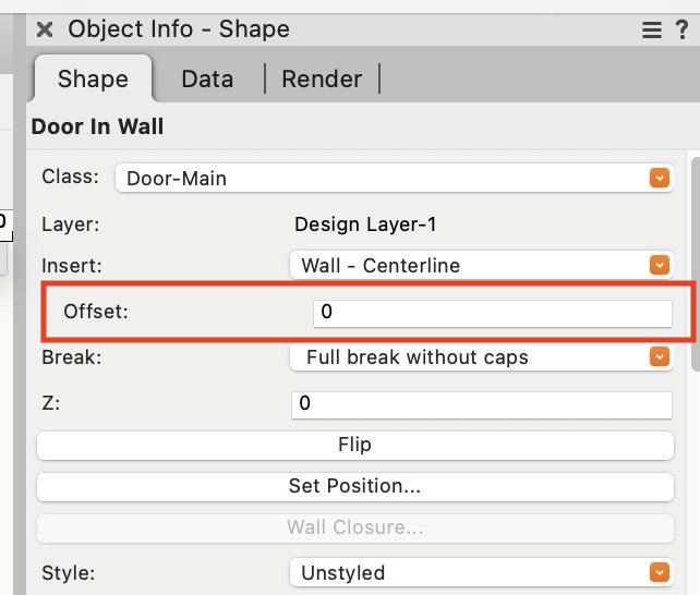
Right-click on the door style in the Resource Manager to open the Plug-in Object Style Options dialog or right-click on the door object in the drawing to open the Plug-in Object Options dialog
*head smack* Indeed. There it is. At the very top. I searched throughout the entire rest of the OIP, but didn't go above "height" because before there was nothing useful up there before. Chalk it up to idiocy!
-
Thanks to those who answered...
@Tom W....I do not see an offset option anywhere in the OIP. It used to be under the Swing Operation I believe. I am running 2022 SP3. Maybe I didn't update at some point and it came back?
@Christiaan I do not know how to get to this Plug-In Object Styles Options. I will have to have a look. It is an unstyled door.
-
Today I went to offset a door in a wall, to move it an inch off center towards an edge, and the option doesn't appear to be there any more. There looks to be some new option to alight it to the left, center, or right, but the doesn't do the same thing. Am I missing something? How can I offset a door by a specified amount?
-
On 8/23/2022 at 9:47 PM, Miguel Barrera said:
Yes, the buttons can only be created with an event enabled script, Sorry, I am so use to them that I overlooked this fact. See Object events , example 3, for the button creation. But the code could work with a field that can register the change such as a check box.
Thank you @Miguel Barrera and @Julian Carr. I have been working with the examples you've given for the past couple of days trying to figure out event-enabled scripts and what all the little widget things do and how they interact with other things. To say they are a whole different animal from standard Vectorscript is an understatement. I've been coding in Vectorscript for many years, but Event-Enabled is truly turning my mind into spaghetti. I'm always amazed at the sheer lack of examples for things like this that aren't more than very simple, single-action scripts. Something I could reverse-engineer. I shall keep plodding on in my journey.
-
 1
1
-
-
4 hours ago, Pat Stanford said:
The Spotlight fields with the degree symbol are the text representation for display (and input) purposes. The real number is stored in a hidden field.
You can hide PIO fields by starting the name with two underscores (__) or by using code to force them to be hidden.
Yeah...I figured out what you meant after posting. At first I thought you meant a static text field just showing a degree representation of what you typed in a separate number field. But I can see the text field idea. Will play with that.
I do know how to hide fields, so no issue there. Thanks for the help!
-
6 minutes ago, Pat Stanford said:
If this is a PIO you are writing, you probably need to have two fields. One formatted as Number to store the actual value in degrees and one formatted as text to display with the degree mark.
Make the actual number field hidden and as part of the PIO strip the units out of the text version, store it in the number field and then store it back to the text field with the proper units. That way if someone enters 87.6 deg, you can grab the 87.6 as the number and store it back into the text field as 87.6°.
Oh, okay. I thought I was missing something. I don't need to have a separate display for the angle, just wanted it in the entry field. Spotlight fixtures do have degrees in some of the fields, so I was hoping it was possible.
Oh, wait. I misread. I see what you were talking about with the two fields.
-
1
-
-
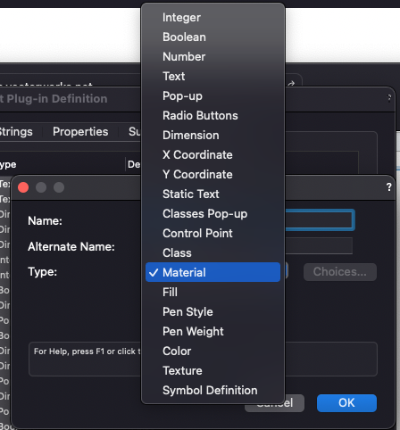
What's the proper way to have PIO fields formatted with degrees? I've tried with number values, but it doesn't allow units, and dimension seems to only format in document units.
-
On 8/18/2022 at 8:29 PM, Miguel Barrera said:
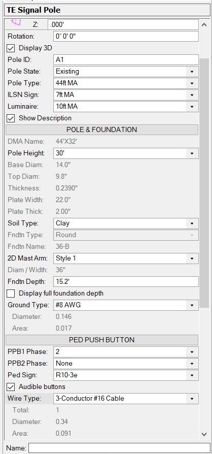
I have coded something similar to what you want. Several years ago, I faced the same problem where I had a lot more fields than I could display. Although all my plugins are event enabled I came up with this solution before there was event enabled plugins so I do not think it is required. In the following you will see buttons for each section. When you click on each, it will display more fields under it. In the example below, the button "Pole & Foundation" displays a few fields and the button "Ped Push Button" displays only one. When clicked on each of these, they display all the fields associated with each button.
The concept is to keep a hidden field with the state of each button. 0 for closed and 1 for open. When setting the field visibilities, I hide the filed if the button is 0 or display the field if the button has a value of 1. In the example below, there are 7 buttons. On the left they are "closed" so the state value is 0000000. When I click on the first, it displays all the fields. When I change the value on the second button from "none" to "2", it displays the fields under that button. The state value is consequently 1100000
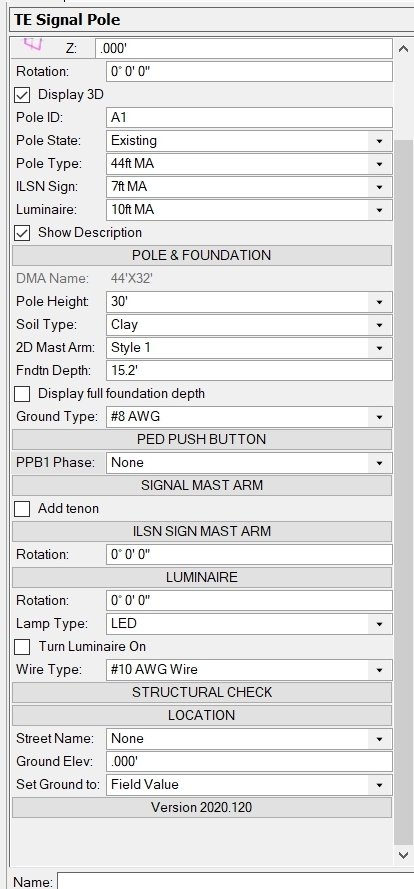
That looks fantastic and would work well. But I am not aware of any button field defined in the Vectorscript field options. And man, I really wish that texture field brought up a texture picker, or the color brought up a color picker. So many things that could be done!

-
On 7/20/2022 at 11:06 PM, Julian_Carr said:
Yes it requires an event enabled PIO. Here is a code snippet:
CONST
kWidgetGroupMode          = 81;
kWidgetSeparator          = 100;
kWidgetGroupAutomatic     = 2;
VAR
gb1 : BOOLEAN;

gb1 := SetObjPropCharVS(kWidgetGroupMode, Chr(kWidgetGroupAutomatic));
gb1 := vsoAddWidget( 1, kWidgetSeparator, 'MY FIRST GROUP' );
    gb2 := vsoAddParamWidget(2, 'ParamName1', 'Actual Param Name 1 to Display in OIP');
    gb2 := vsoAddParamWidget(3, 'ParamName2', 'Actual Param Name 2 to Display in OIP');
    gb2 := vsoAddParamWidget(4, 'ParamName3', 'Actual Param Name 4 to Display in OIP');
gb1 := vsoAddWidget( 5, kWidgetSeparator, 'MY SECOND GROUP' );
    gb2 := vsoAddParamWidget(6, 'ParamName4', 'Actual Param Name 4 to Display in OIP');
    gb2 := vsoAddParamWidget(7, 'ParamName5', 'Actual Param Name 5 to Display in OIP');
    gb2 := vsoAddParamWidget(8, 'ParamName6', 'Actual Param Name 6 to Display in OIP');
Additionally you could add vsoWidgetSetIndLvl(8, x ); if you wanted to further indent one of the parameters, where X = 1 or 2 or 3 being how far it is indented.
Hmmm...thank you. I will have to look into this. I have the entire plug-in working. Does changing it to event-enabled change how any of the rest of it operates, or will the standard code still run just fine, while these new portions affect the OIP?
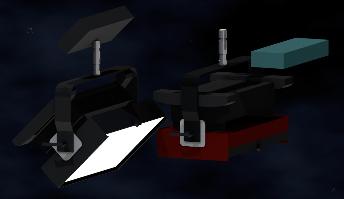
Transparency refraction changes if object is in a symbol?
in Rendering
Posted
I've been working on some lighting fixtures with glass lenses. I got the lenses looking really nice with some glass refraction. But since I'm using so many of them, I decided to make the individual lens a 3D symbol. So, I selected one of the lenses and made it a symbol. But, the symbol will not take on the same nice refractive properties of the individual meshes. The mesh inside the symbol is the exact same as the meshes not inside the symbol. Same rendering settings, same everything. It's literally a copy/paste. But the refraction does not work. Look at the center lens on the fixture...that one is the symbol while the rest are individual meshes. It just renders white.
The texture is a grey color, with a glass reflection, and glass transparency with 1.8 refraction.
Any ideas?