


SamIWas
-
Posts
409 -
Joined
-
Last visited
Content Type
Profiles
Forums
Events
Articles
Marionette
Store
Posts posted by SamIWas
-
-
Would be at least helpful to see a screenshot of your viewport settings in the OIP. That might help answer a lot of questions.
-
On 1/16/2024 at 1:39 AM, ilijahmora said:
@klinzeySo how do we make fixutres brighter now? Often times during the design/sketch process, a quick way is needed to stomp out a visual.. and being able to multiple the brighness percent or crank up the emitter was the ticket. How do you suggest we do this now?
You can use the light palette, select the light, and make it brighter there. It does allow you to go above 100 in there.
-
 1
1
-
-
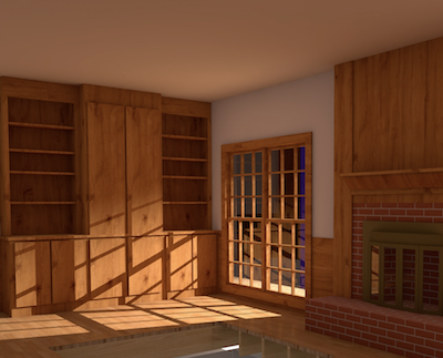
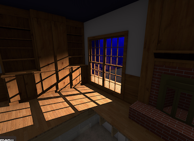
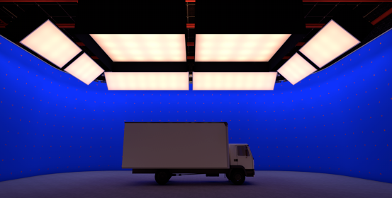
I have started rendering 360° panoramas for our team to see some plans in full view. They love it. But, I've found that the panorama doesn't appear to pay attention to the indirect lighting setting in custom renderworks. I've attached two images. One from a render using custom renderworks in a viewport, and one from the panorama render. As far as I can tell, all settings are the same. Is there a setting I'm missing somewhere, or does panorama not use indirect lighting?
-
On 1/14/2024 at 8:21 PM, The Hamma said:
This is actually what I’m working on. I have written two, scripts that I use to call the functions from stream deck with a shortcut. It calls the script and then has user input for the tool name. This is where I have stream deck, enter the name of the tool. Or the index. Which then is executed by the script.
my scripts are attached.
I am using control+shift+alt+X for the tool shortcutAnd control+shift+alt+Z for the menu shortcut
If I ever finish my stream deck profile, I will upload itPROCEDURE StreamDeckCommand; {Input the command name with the index at the end of the name. Use two digits for the index name. ie. for 1 use 01 for 0 use 00. Print command would be "Print00", Font Size 4 command would be "Font Size01" and Font size 144 would be "Font Size17"} VAR SDstring,SDStrInt:STRING; SDLen,SDInt:INTEGER; BEGIN SDstring:=StrDialog('Command to run',''); SDLen:=Len(SDstring); SDStrInt:=Copy(SDstring,SDLen-1,2); SDInt:=Str2Num(SDStrInt); SDstring:=Copy(SDString,1,SDLen-2); if SDstring <> '' THEN DoMenuTextByName(SDstring,SDInt); END; RUN(StreamDeckCommand);PROCEDURE StreamDeckTool; {Either input the tool name or the tool index} VAR Istool,SDstring:STRING; Result:BOOLEAN; BEGIN SDstring:=StrDialog('Command to run',''); Istool:=Copy(SDstring,1,1); if SDstring <> '' THEN BEGIN IF Istool = '-' THEN Result:=SetToolbyIndex(Str2Num(SDstring)) ELSE Result:=SetToolByName(SDstring); END; END; RUN(StreamDeckTool);Just after I posted, I found SetToolByName or whatever and got it started. But I'll look at yours, too.
-
5 hours ago, Pat Stanford said:
I just tested and
B1:=CallToolByName('Door Tool');
B1:=CallToolByName('Door Tool');works.
I have not tested the others.
Any idea what would cause this to work on some of my custom tools, but with others, it flashes the tool in the pallete real quick then returns to the selection tool?
I was getting excited to write my own shortcut selector for my StreamDeck since the native shortcut system is almost full. But I can't do it if it won't actually select the tools.
-
5 hours ago, michaelk said:
You CAN encrypt plug-ins in 2024 one at a time using the method in my post above.
I don't go for all the fancy stuff Josh, Jesse, and Sam do. 🙂
Yeah, I saw that method. But then if I want to keep my original script the same name, but encrypt one also with that same name, I don't want the original overwritten. Do you copy one out off the directory first before you do that?
-
28 minutes ago, Jesse Cogswell said:
@JBenghiat is referring to either the EncryptPlugin function or the EncryptAllPlugins function. These are not included in the standard VW installation, you have to download the SDK and extract the BatchEncryption.vlb file and put it in your User Folder. As a short note, the link in the online Function Reference is broken, so use this one instead to get the SDK file. It looks like the SDK for 2024 isn't available yet. The .vlb file will only work for the year that you downloaded (at least that's been my experience).
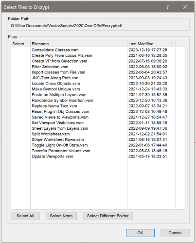
I have a custom plug-in that I wrote to encrypt my plug-ins that basically takes in a folder and populates a List Browser with .vso, .vsm, and .vst files sorted by last modified date. When you press OK, it encrypts all selected files. This is nice because I can put all of my files in a remote location from my User Folder, so the plug-ins stay editable for me but easily accessible for sending out to folks.
That is helpful info. So are you saying that I can't encrypt plugins in 2024 yet because the 2024 SDK isn't available yet? I'll download 2023 and try it out at least.
That's a nifty little plugin you got there!
-
On 10/2/2023 at 7:40 PM, JBenghiat said:
My guess is this is just an issue with the feedback string, and you can click ok.
That said, I haven’t encrypted this way in years: I always use the batch encryption commands. The advantage is that the plug-in you’re encrypting doesn’t need to be in your plug-in folder, so you can encrypt a copy and not have to worry about locking your original script. I’m fairly sure you can search the forum for an earlier post on the subject
Hey Josh...are you referring to the "Encrypt Script..." command in the plug-ins menu? I am trying to encrypt some VectorScript .vso files and it won't let me select .vso . I obviously don't want to overwrite the original, so I will create a copy and do it from there, but I'm missing something somewhere.
-
On 11/14/2023 at 8:43 AM, chris444 said:
Good morning!
I am currently working on a project that requires a led tape fixture (specifically the Elation 60ip) to have the lens glow. I have seen this topic and seen the user guide pdf about this but I still cant seem seem to get it to work. Is there a full step by step guide (preferably in video form) for this kind of process?
I use a texture with a glow applied, assign the lens object to the lens class, then assign the lens class to take on spotlight fill colors.
-
1
-
-
23 hours ago, Sam Jones said:
If we are not talking about the default OIP, this is easily done. In the Reset Event, you need the following statements
IF vsoStateGetParamChng(PIOHan, OutWidgID, ParamIndex, OldValue ) THEN
BEGIN{Check if the changed parameter is equal to the one you want to base the change of another parameter on}
{Get the value of the changed parameter}
IF theValue is a signal to change another drop down THEN
BEGIN
booResult := vsoPrmName2WidgetID('',NameOfParameterToChange, OutWidgID);
vsoWidgetPopupClear(OutWidgID);
FOR index := 1 TO NumberOfChoices DO
BEGIN
vsoWidgetPopupAdd(OutWidgID, NewValue[index], NewValue[index]);
END
END; {IF theValue is a signal to change}
END; {IF vsoStateGetParamChng}
Cool! I'll play around with this!
-
I'm more curious about getting different drop-down values conditionally based upon a different drop-down's value. Looks like something else to have fun learning!
-
On 11/8/2023 at 12:13 PM, markdd said:
Just a thought. If you create your front texture with a 65% grey colour as opposed to white, then if you ramp up the glow value to 250% then you might get closer to the result you are after without the bother of using an area light.
Man...I've been so busy, I forgot to check the forum. I'll give this a go and see if it does anything.
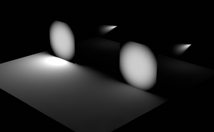
What I'd really love is an option in the "override environment lighting" or whatever it is in the texture, for there to be an option to multiply the amount of lighting the texture puts out. But it wouldn't affect the visibility of the texture itself. An example from cinema is attached. Two squares backlit by the same brightness light, with exactly the same texture settings, except one texture has GI boosted up to 2000%. Teh squares appear identical, but the amount of light put out is different.
-
3 hours ago, bjoerka said:
Maybe use a combination of a backlit texture or a glowing texture and an area light.
I just did a quick test with one hollow box, a thin extrude with a transparent texture in front and an area light inside the box.
May this is a way to achieve what you are looking for when you separate the texture and the light to get better control about the look.
1st image with only glowing surface, 2nd with area light inside the box.
Yeah...this was an option I thought about. But with the way everything moves and tilts and the lights inside change colors depending on the set, etc, it would be a lot of extra work to maintain the area lights. I was hoping for an option in the indirect lighting. It's not show crucial or anything.
-
11 hours ago, markdd said:
I don’t think so. However, you could make two textures added to two surfaces inside the light boxes.
An inner surface could contain a glow texture purely for lighting at 250%.
An outer surface with a “decorative” glow texture set to 100% and not to “cast shadows”. That way you should get the best of both lighting and realism.
Hmmm...that is an interesting thought...going to try that one.
Nope...It appears that environment lighting doesn't pay attention to and texture's shadow casting properties.
-
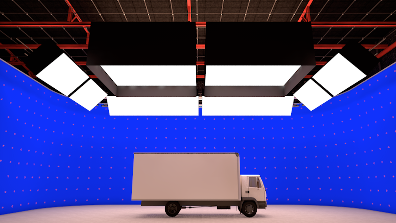
I've been wondering for quite a while...is there any real way to control the amount of global illumination a texture creates without affecting the actual rendering of the texture itself? Cinema4D has an option in the material for how much global illumination to generate, but it doesn't affect the rendering of the material itself. In the attached image, the light boxes render very well and look realistic, but there is almost no actual light being generated onto the truck. If I up the backlit part of the texture to from 100 to 250, I get the right amount of light onto the truck, but the boxes just blow out white.
My goal is to get the boxes to look like the first image, and the floor and truck to look like the second image.

-
5 hours ago, bcd said:
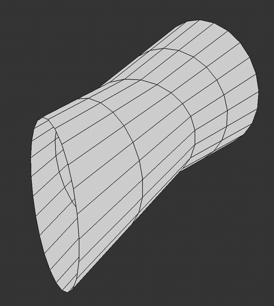
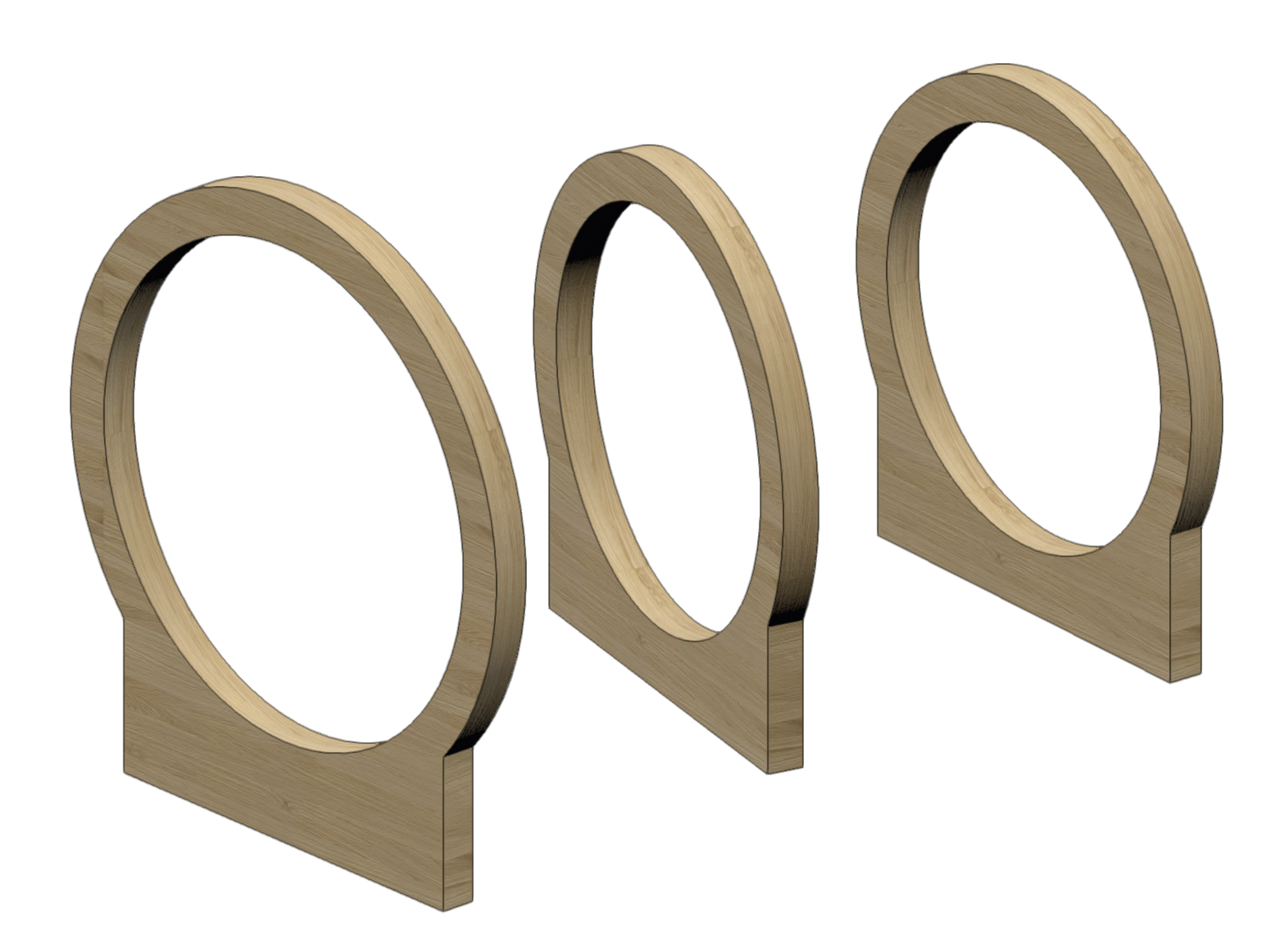
Extract a nurbs curve from the edge of each rib. If you get a group, ungroup and Modify>Compose.
Now you should have 3 ovals nurbs curves that you can loft
Awesome! Thank you! That got me going in the right direction.
-
I am working on a set plan which will have a bunch of ring ribs forming the backbone for a tunnel. I am trying to figure out the best way to create the tunnel portion in between the ribs. In Cinema 4D, this is simple...create multiple circle splines, then put them in a loft, and it will connect them in 3D. I do a lot of 3D in vectorworks, but this one is beyond what I'm familiar with. If the circles were parallel to each other, it could be done with matrix extrude. But the circles are not parallel and are at different heights. Any leads on the best way to accomplish this?

-
Man, I'm glad I found this topic. This was driving me crazy today. I don't know how this "feature" is supposed to work, but it works very badly.
-
5 hours ago, JBenghiat said:
You can, however, place a Lighting Pipe at the bottom of the beam, and turn off the “draw pipe” option. This will give you a snappable line with the possibility of tick marks. You can definitely place a Lighting Pipe inside another PIO, but I’m not sure if it will still be detected as a rigging object.
I managed to get the PIO to draw the pipe and apply all of the relevant info into the fields to make the pipe act how I want. But, yeah, I don't think it can be detected inside the PIO as a rigging object. I don't even care about rigging analysis...I just want the lighting device to pick up the position name and move if the PIO is moved. That's a bummer.
-
2 minutes ago, SamIWas said:
I was just coming to respond that I got it started with CreateCustomObject. I managed to get it to draw a pipe, but only 1m long no matter what I assigned to the record fields. It also wouldn't take on a diameter from 'Lighting Pipe','PipeW' (which is what I got from the worksheet as the parameter name. So, I will look into the createcustomobjectPath.
I'm not quite sure what you mean by "the profile group" however. What's odd, and this may be related to what you are talking about here, is that no other objects draw in the plugin. I have a few random extrudes just as test pieces, and they do not draw. I'm guessing this has to do with the profile group thing you mention.
I will also look into this debugview. I have read about it on other posts, so maybe that is something I need.
Oops...accidental quote.
-
17 minutes ago, JBenghiat said:
CallTool isn't going to work for you. The tool will want to collect two points, then (I recommend) use vectors to calculate the length and rotation.
Use the CreateCustomObject commands to place the pipe and/or create a Hanging Position. The universal name for the Hanging Position is "Light Position Obj".
Use SetRField to set parameters. I know there's been posts on the forum about DebugListView, which can help you find universal names and hidden parameters. You can also construct a sample Hanging Position and examine the output of Export VectorScript.
The pipe is path-based, so either call CreateCutomObjectPath, or set the path group after creating the object (the path should be a polyline).
Any geometry in the Hanging Position needs to be inserted in its profile group.
The trickiest thing is translating been the plug-in's internal coordinates and the coordinates of the overall world.
I was just coming to respond that I got it started with CreateCustomObject. I managed to get it to draw a pipe, but only 1m long no matter what I assigned to the record fields. It also wouldn't take on a diameter from 'Lighting Pipe','PipeW' (which is what I got from the worksheet as the parameter name. So, I will look into the createcustomobjectPath.
I'm not quite sure what you mean by "the profile group" however. What's odd, and this may be related to what you are talking about here, is that no other objects draw in the plugin. I have a few random extrudes just as test pieces, and they do not draw. I'm guessing this has to do with the profile group thing you mention.
I will also look into this debugview. I have read about it on other posts, so maybe that is something I need.
-
36 minutes ago, SamIWas said:
Hmmm...okay. I'll have to look into that and how to create the lighting pipe inside a PIO and make it invisible. That would absolutely work for everything I want to do. Because I also want to create my own pipe PIO because you can't texture the Lighting Pipe or the straight truss tool, unless the texture is a class texture (and then, you can't turn it off!). You also can't just apply a generic color to the pipe, and a grid of bright white pipes looks ridiculous. If either of these are possible, I haven't found it. Very annoying, and I want to fix that!
EDIT: Ha! My first attempt left Vectorworks with all greyed out menus and no way to get out of it. So CallTool(47) without some way to complete it was not the answer! 😂
-
2 hours ago, JBenghiat said:
@SamIWas You raise several questions here.
Any object can be turned into a Hanging Position, and this can be accomplished with VectorScript. This would be the same as selecting the object, then choosing the Create Hanging Position command.
In order to modify the geometry, you would have to edit the Hanging Position’s profile group.
If you are asking if any object can be turned into a Rigging Object so that it directly interacts with Lighting Devices and loads, but still has options available in the OIP (without editing the profile group), then no. Rigging Objects need to be able to “answer” a certain set of questions that Vectorworks “asks” of them, and this is only possible via the SDK.
In terms of snapping to the I-beam, this also wouldn’t be possible without the SDK. You can, however, place a Lighting Pipe at the bottom of the beam, and turn off the “draw pipe” option. This will give you a snappable line with the possibility of tick marks. You can definitely place a Lighting Pipe inside another PIO, but I’m not sure if it will still be detected as a rigging object.
What you envision is definitely possible with the SDK. In VS, you can design a custom tool that draws a beam, places a Lighting Pipe for snapping, and wraps them in a Hanging Position.
Hmmm...okay. I'll have to look into that and how to create the lighting pipe inside a PIO and make it invisible. That would absolutely work for everything I want to do. Because I also want to create my own pipe PIO because you can't texture the Lighting Pipe or the straight truss tool, unless the texture is a class texture (and then, you can't turn it off!). You also can't just apply a generic color to the pipe, and a grid of bright white pipes looks ridiculous. If either of these are possible, I haven't found it. Very annoying, and I want to fix that!
-
Trying to get more info for this. @Sam Jones, did you ever get this working? I'm looking to make some very simple PIOs that can automatically be hanging positions, but still be editable using the PIO fields. An example would be a truss with an Ibeam along the bottom (used a lot in film sets) where I can draw the truss, and the beam, and have the beam portion be a hanging position. Or the whole thing is fine I guess as long as I draw it correctly and the fixtures will snap to the bottom center of the PIO.

3D Model Keyboard
in Rendering
Posted
3DWarehouse has ton of options for this. No, they aren't Vectorworks models, but you can import them and they will work. Here's one of the Hammond B3 models.