SamIWas
-
Posts
409 -
Joined
-
Last visited
Content Type
Profiles
Forums
Events
Articles
Marionette
Store
Everything posted by SamIWas
-
Would anyone be up for an object-building "challenge"?
SamIWas replied to SamIWas's topic in Vectorscript
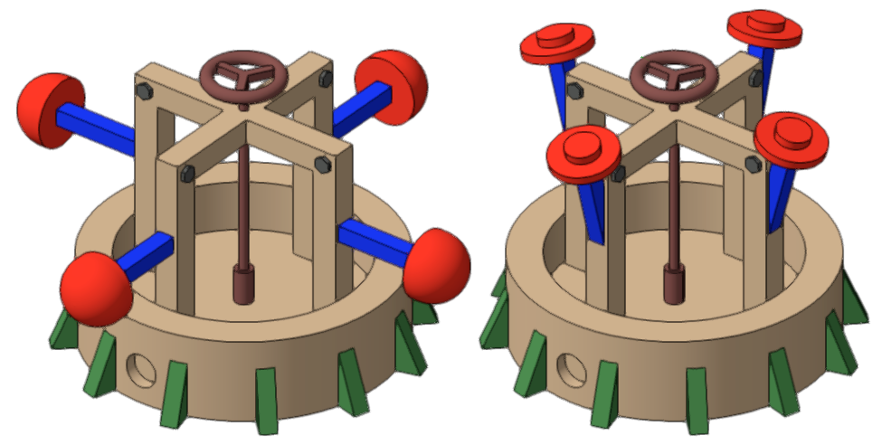
As Michael said, it's about the parameters. In my provided example, I can change the shape of the red end pieces and the angle of the four arms. I have others that allow a huge amount of customization to some very large and complex objects like boom lifts and scissor lifts. -
Would anyone be up for an object-building "challenge"?
SamIWas replied to SamIWas's topic in Vectorscript
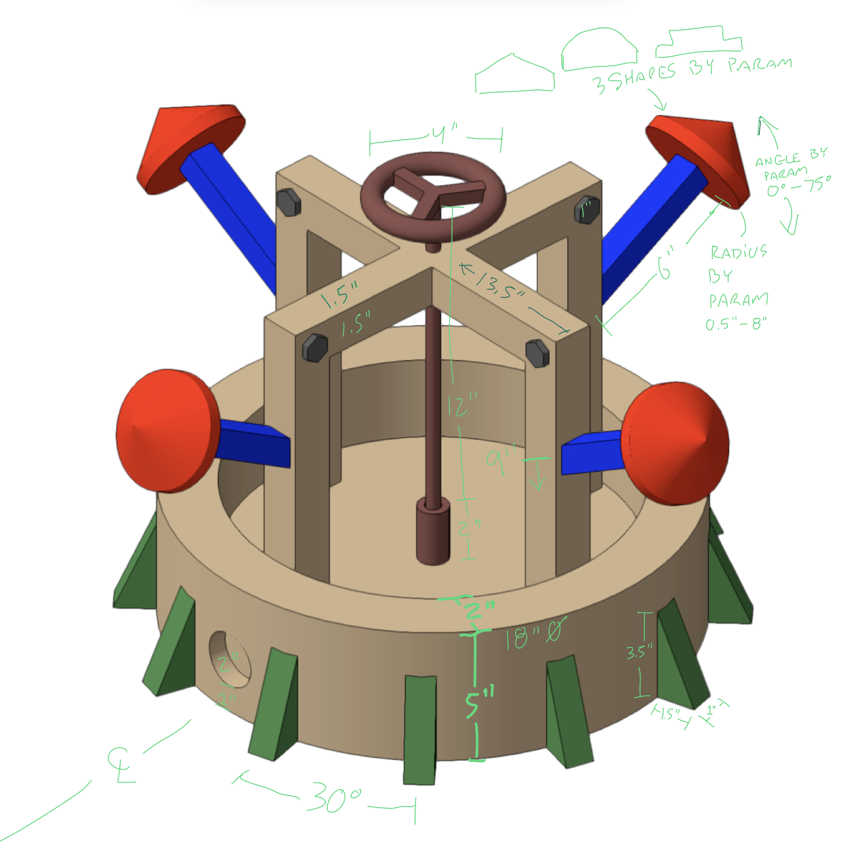
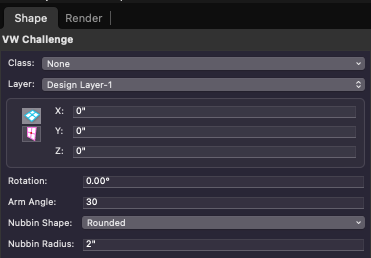
And my code...my code is fairly simple and not meant to be a complex, event-enabled object. This was more about just the code to draw the parts. Took about 75 minutes from start to finish to write and test the whole thing. I'd really love to see how others code this kind of thing to see if what I've done is in line with more established programmers. Particularly in the way that sweeps and extrudes are created and then constantly rotated into the right orientation. {IllumiViz VW Challenge Plug-In Version 1.0 Last Updated 10/16/23 6:15pm EST} PROCEDURE VWChallenge; VAR objname : STRING; result, markertest : BOOLEAN; oh,rh,wh : HANDLE; count, subtract, addition : INTEGER; armang,nub : REAL; ctan, cgreen, crust, cred, cblue, cgrey : LONGINT; s1, s2, s3, a1, a2, a3, part1, part2, armg : HANDLE; BEGIN {--------------------SYMBOL INFO-----------------------} PushAttrs; {--------------------MENU INFO-----------------------} nub:=PNUBSIZE; IF nub<0.5" THEN BEGIN nub:=0.5"; SetRField(oh,objname,'NubSize',num2strf(nub)); END; IF nub>8" THEN BEGIN nub:=8"; SetRField(oh,objname,'NubSize',num2strf(nub)); END; armang:=PARMANGLE; IF armang<0 THEN BEGIN armang:=0; SetRField(oh,objname,'ArmAngle',num2str(2,armang)); END; IF armang>75 THEN BEGIN armang:=75; SetRField(oh,objname,'ArmAngle',num2str(2,armang)); END; {-------------COLOR AND TEXT DEFINITIONS-------------} FPatByClass; FillColorByClass; OpacityByClass; LSByClass; LWByClass; PenColorByClass; markertest:=SetDefaultBeginningMarker(1,15,0.25",0.125",1,1,FALSE); markertest:=SetDefaultEndMarker(1,15,0.25",0.125",1,1,FALSE); Closepoly; RGBtoColorIndex(53500,43500,34000,ctan); RGBtoColorIndex(16500,33000,16500,cgreen); RGBtoColorIndex(30500,16500,16500,crust); RGBtoColorIndex(65535,5000,5000,cred); RGBtoColorIndex(5000,5000,65535,cblue); RGBtoColorIndex(20000,20000,20000,cgrey); {--------------------CREATE 3D-----------------------} NameClass('None'); FillFore(ctan);FillBack(ctan); BeginSweep(0,360,10,0); {main circle} Locus(0",0"); Poly(0",0", 9",0", 9",5", 7",5", 7",2", 0",2", 0",0"); EndSweep; s1:=LNewObj; Set3DRot(s1,90,0,0, 0",0",0"); BeginSweep(0,360,22.5,0); {indented circle} Locus(0",0"); Poly(0",0", 1",0", 1",0.75", 0",0.75", 0",0"); EndSweep; s2:=LNewObj; Move3DObj(s2,0",-9",2"); subtract:=SubtractSolid(s1,s2,s3); DelObject(s1); DelObject(s2); BeginXtrd(-0.75",0.75"); {arch} Poly(-6.75",0", -5.25",0", -5.25",10.5", 5.25",10.5", 5.25",0", 6.75",0", 6.75",12", -6.75",12", -6.75",0"); EndXtrd; a1:=LNewObj; Set3DRot(a1,90,0,0, 0",0",0"); Move3DObj(a1,0",0",2"); BeginXtrd(-0.75",0.75"); {arch} Poly(-6.75",0", -5.25",0", -5.25",10.5", 5.25",10.5", 5.25",0", 6.75",0", 6.75",12", -6.75",12", -6.75",0"); EndXtrd; a2:=LNewObj; Set3DRot(a2,90,0,90, 0",0",0"); Move3DObj(a2,0",0",2"); addition:=AddSolid(a1,a2,a3); DelObject(a1); DelObject(a2); FillFore(cgreen);FillBack(cgreen); part1:=NIL; BeginXtrd(-0.5",0.5"); {side triangles} Poly(0",0", 1.5",0", 0",3.5", 0",0"); EndXtrd; part1:=LNewObj; Set3DRot(part1,90,0,0, 0",0",0"); Move3DObj(part1,8.9",0",0"); Set3DRot(part1,0,0,15, 0",0",0"); FOR count:=1 to 11 DO BEGIN part2:=NIL; part2:=HDuplicate(part1,0",0"); Set3DRot(part2,0,0,count*30, 0",0",0"); END; FillFore(crust);FillBack(crust); BeginSweep(0,360,22.5,0); {post collar} Locus(0",0"); Rect(0.3",0", 0.55",2"); EndSweep; Set3DRot(LNewObj,90,0,0, 0",0",0"); Move3DObj(LNewObj,0",0",2"); BeginSweep(0,360,22.5,0); {post} Locus(0",0"); Poly(0",0", 0.25",0", 0.25",14", 0",14", 0",0"); EndSweep; Set3DRot(LNewObj,90,0,0, 0",0",0"); Move3DObj(LNewObj,0",0",2"); BeginSweep(0,360,10,0); {wheel ring} Locus(0",0"); Oval(1.625",-0.375", 2.375",0.375"); EndSweep; Set3DRot(LNewObj,90,0,0, 0",0",0"); Move3DObj(LNewObj,0",0",16"); BeginXtrd(-0.25",0.25"); {wheel ribs} Poly(0.783",1.857", 1.217",1.607", 0.289",0.000", 1.217",-1.607", 0.783",-1.857", -0.144",-0.250", -2.000",-0.250", -2.000",0.250", -0.144",0.250"); EndXtrd; Move3DObj(LNewObj,0",0",16"); FillFore(cgrey);FillBack(cgrey); part1:=NIL; BeginXtrd(-1",1"); RegularPolygon(0",0",12.7,6,1); SetPolyClosed(LNewObj,TRUE); EndXtrd; part1:=LNewObj; Set3DRot(part1,90,0,0, 0",0",0"); Move3DObj(part1,6",0",13.25"); part2:=NIL; part2:=HDuplicate(part1,0",0"); Set3DRot(part2,0,0,90, 0",0",0"); part2:=NIL; part2:=HDuplicate(part1,0",0"); Set3DRot(part2,0,0,180, 0",0",0"); part2:=NIL; part2:=HDuplicate(part1,0",0"); Set3DRot(part2,0,0,270, 0",0",0"); BeginGroupN(armg); BeginXtrd(0",6"); {arm} Rect(-0.5",-0.5", 0.5",0.5"); EndXtrd; SetFillFore(LNewObj,cblue);SetFillBack(LNewObj,cblue); BeginSweep(0,360,10,0); {nubbin} Locus(0",0"); IF PNUBSHAPE='Pointed' THEN Poly(0",0", nub,0", nub,0.5", 0",2", 0",0"); IF PNUBSHAPE='Rounded' THEN BEGIN BeginPoly; MoveTo(0.000",0.000"); LineTo(nub,0.000"); Add2dVertex(nub,nub+0.500",3,nub); LineTo(0.000",nub+0.500"); LineTo(0.000",0.000"); EndPoly; END; {rounded} IF PNUBSHAPE='Stepped' THEN Poly(0",0", nub,0", nub,0.5", nub/2,0.5", nub/2,1", 0",1", 0",0"); EndSweep; SetFillFore(LNewObj,cred);SetFillBack(LNewObj,cred); Set3DRot(LNewObj,90,0,0, 0",0",0"); Move3DObj(LNewObj,0",0",6"); EndGroup; {armg} Set3DRot(armg,0,90-armang,0, 0",0",0"); Move3DObj(LNewObj,6.25",0",9"); part1:=NIL; part1:=armg; part2:=NIL; part2:=HDuplicate(part1,0",0"); Set3DRot(part2,0,0,90, 0",0",0"); part2:=NIL; part2:=HDuplicate(part1,0",0"); Set3DRot(part2,0,0,180, 0",0",0"); part2:=NIL; part2:=HDuplicate(part1,0",0"); Set3DRot(part2,0,0,270, 0",0",0"); PopAttrs; END; Run(VWChallenge); -
Would anyone be up for an object-building "challenge"?
SamIWas replied to SamIWas's topic in Vectorscript
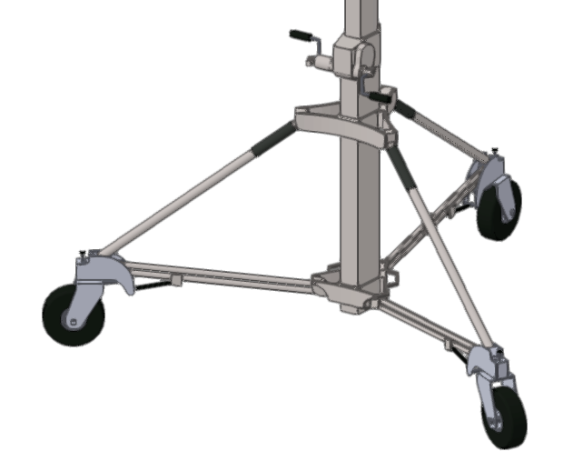
Okay, so, if anyone does want to have a go at it, here is the final object with some reference dimensions. I'll post my code in the next comment.
-
Would anyone be up for an object-building "challenge"?
SamIWas replied to SamIWas's topic in Vectorscript
With the film industry shut down right now, I am full of bandwidth! -
Would anyone be up for an object-building "challenge"?
SamIWas replied to SamIWas's topic in Vectorscript
I do indeed intend on selling some of the stuff I have made. I'm trying to get them "beta tested" right now, and then I need to figure out how to build a selling platform, in which case I might contact you and some others about how you set up your sales portals. I don't think I intend to go so far as to lock the plugins to a serial number (even thought that would probably lose a few sales), because I have no idea how that would even work and it seems daunting. -
Would anyone be up for an object-building "challenge"?
SamIWas replied to SamIWas's topic in Vectorscript
So, this is an object full of random parts that I'm thinking about using. I'll spit out the code sometime tonight and provide some more info.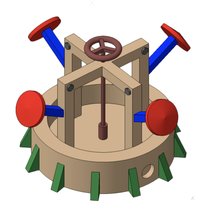
-
A lot of the PIOs I make in Vectorscript are for building objects I use extensively, but need to change depending on inputted variables. I have my way of coding the construction of those objects, but I'm wondering if whatI'm doing is best practice, or if there are ways I haven't thought of. I have learned so much from this forum, I thought it might be fun to see how others might code the building of a mildly complex object. The attached picture is of a lighting stand that is built entirely in Vectorscript using a series of sweeps, extrudes, Solid Additions, Solid Subtractions, etc. It works exactly as planned. But, is it done "right"? Would anyone be interested in a quick little "challenge" to have a provided object that needs to be built in Vectorscript using a few different methods? Nothing nearly as complicated as the attached stand, but using a lot of the same ideas. Something that others could look at and learn from or maybe find out how what they are currently doing isn't the most efficient way? If so, I'll whip up a little example object and post it here.
-
I was days away from asking this exact question (except not in 2024). I have never created an encrypted version of a plugin, but as I plan on distributing soon, I need to know how to do that.
-
I have a layer called "Titleblock" which contains show logos of varying sizes for different sheets, and various blocks for keys, notes, etc. I can update the stuff in that design layer, and then it reflects in every viewport that goes with my title blocks. Not automatic for title blocks themselves, but versatile for lots of different situations.
-
Are these two different instances of the PIO being inserted into the document, or one PIO that draws two parts? How are the two sections created with the pattern? How you're creating it will determine how to fix it.
-
Entering a unique field value for new/duplicated objects
SamIWas replied to SamIWas's topic in Vectorscript
You are correct. I'm pretty sure I built those plugins before 2018. Now...another question...is there a way to write TO Vectorworks UUID? As in, overwrite the value VW gives it? Because with my VW/Filemaker data transfers, I sometimes have object created in Filemaker first which then get imported back into VW. The objects in Filemaker are given a UUID which would need to track to VW. So as part of the import process, I would want to tell VW what the object's UUID is. -
Entering a unique field value for new/duplicated objects
SamIWas replied to SamIWas's topic in Vectorscript
Holy moly. How did I never see the getUUID command??? I've been creating them using CreateUUID and applying them to text fields for years using all these tricks to create new ones....and, of course, VW just does it. Guess I need to do another round of updates! -
For most of my PIOs, I have a unique ID field used for importing and exporting to FileMaker Pro. I have always done this by having an ID field, entering the same value into the Object Name, then changing the ID field if the two don't match (since VW will change the name of any conflicting object names automatically). But, now that I've learned about 3.7% of how to use Event-Enabled objects, I'd like to make this work in a more standard way. I tried doing this in the kObjOnInitXProperties section, which I think runs when the object is new or duplicated (?), but I couldn't seem to pull object field data in there. I also couldn't pass a variable from that section into the rest of the code. Where in the event code can I assign a variable with a UUID, which changes only if the object is new or duplicated, and pass that into the main code to change the ID field if it's different?
-
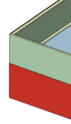
I'm building a PIO with a few extrudes in it. Each one is assigned to a different class. The classes have both fill colors and textures applied. In the OIP, I have a drop down menu called "Use Textures" which has the options "None", "Class Textures", and "Custom Textures". When the "None" option is selected, I'd like the objects to just take on their class fill colors. I thought that using SetTextureRefN with a -2 index on the 3 partID would set the texture to none, but it does not appear to do so. In the example shown below, the wrap around at the top is set to the "Box" class. The "Box" class has a dark grey fill, and a light green texture for testing. I am using the following code: BeginXtrd(0",ph); Poly(---poly coordinates---); SetPolyClosed(LNewObj,FALSE); EndXtrd; IF PUSE_TEXTURES='None' THEN SetTextureRefN(LNewObj,-2,3,0); Is there something I'm missing, or does this not work the way I think it does?
-
I thought about doing a bubble sort, but as you said...it's quite inefficient. Actually, doing the trunc(x/1000)*1000 is exactly how the value is entered into the array. I do that frequently for value calculations and display. What I have ended up doing is adding a third column to the structure. one value is entered to three decimal points, then the other value is added, but divided by ten million. So an X value of 375.268 and a Y value of 198.376 goes into the sort column as 375.268000198376. If I sort by Y, it reverses the two. This seems to work and is much more efficient than a bubble sort.
-
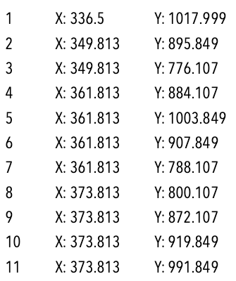
So, in the image below are the coordinates of some objects in my file as reported by the script and entered into the array. The coordinates were entered randomly as it picked up objects. When I sort by X (column 1), I will get all the X column in order, as expected. Note that several X values are the same, but Y values are different. If I want it sorted by X, and then Y, I hoped that I could sort by column 2, and then column 1. But, that doesn't work. In the meantime, I might divide the Y value by ten million or something and add that to the X value, giving a point value sort in a single column.
-
Using SortArray is easy when sorting an array by a single column. I can't find a method for sorting by two columns. For instance, I have an array with X and Y values. I want the array sorted by X, and then Y. I tries sorting Y first, then X, hoping that it would hold the Y sort, but it does not. I've considered making a third column which is just "sort order" and some method of the two values combined to make a sortable list. Is there a better method?
-
It's my understanding that PenPat or PenPatN 1-71 match the fill styles...the pixelated patterns. If you use a negative PenPat, then it becomes a dash style.
-
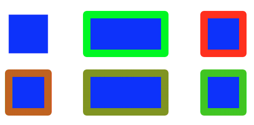
That was the issue. Very odd. But PenPat 1 isn't a dash style. It's the PenFore color, while PenPat 2 is the PenBack color. PenFore 0 is no pen, but it makes the 3D Loci appear. The boxes below are PenPatN(0) through PenPat(5). When extruded, they appear only with the PenFore Color, except for 3D loci. Very bizarre behavior, but at least I can control it now! Thank you.

-
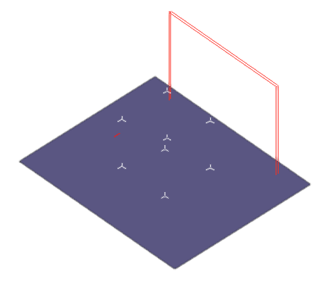
@Marissa Farrell Here is just a quick little Locus Test. It makes a small array of both 2D and 3D locus points. The 2D Loci take on the color, while the 3D ones do not. PROCEDURE LocusStuff; VAR markertest : BOOLEAN; BEGIN PushAttrs; NameClass('None'); FillPat(1); FillFore(0,0,65000); FillBack(0,0,65000); PenPatN(1); PenFore(65000,0,0);PenBack(65000,0,0); OpacityN(100,100); markertest:=SetDefaultBeginningMarker(1,15,0.25",0.125",1,1,FALSE); markertest:=SetDefaultEndMarker(1,15,0.25",0.125",1,1,FALSE); Locus(-12",0"); Locus(0",12"); Locus(12",0"); Locus(0",-12"); Locus3D(-12",12",12"); Locus3D(-12",-12",12"); Locus3D(-12",12",-12"); Locus3D(-12",-12",-12"); Locus3D(12",12",12"); Locus3D(12",-12",12"); Locus3D(12",12",-12"); Locus3D(12",-12",-12"); SetPenFore(LNewObj,3);SetPenBack(LNewObj,3); {this one to test indiviudal color assignment} BeginXtrd(-30",30"); Rect(-30",30",30",31"); EndXtrd; PopAttrs; END; Run(LocusStuff); 3D Locus Test.vso
-
Yeah, I'll see if I can whip something up.
-
I had a friend request a script that places a Renderworks camera and focuses it according to another object's position. There are no built-in functions like there are for lights (at least that I can see), but I was able to place a camera. When looking at a worksheet or criteria to get an idea of fields that I can adjust, since the script places the camera with all zero settings, it looks like most of the field names are blank. I'd like to be able to adjust the focus distance and the look-to height, amongst other things. Anyone ever used a PIO or script to place a camera?
-
I use 3D loci quite a bit for reference points in plugins. Usually, I either delete them or hide them after needed in the code, but sometimes I use them as snap points for outside things. But, in all of my PIOs, my 3D loci are white and not visible unless there's a dark background. I've tried assigning them to different classes. I've tried setting their pencolors to black. I've tried giving them a pen size. But they just stay white. If I put a 3D locus in my document, it's the selected pen color and visible. So I know that it's not the wrong settings for loci visibility. What gives??
-
Thank you as always! That got me what I needed!
-
I feel like I've done this before, but blanking out. Seems like this should be a no-brainer. Trying to write a script which will enter the same info into the fields of multiple different types of custom PIOs. In order to do that, I assume I will use SetRField(handle,nameofpio,fieldname,info). But for some reason, I can't find the right command to property pull the name of a pio. So, if I have a Network Switch and a Data Rack selected, the script would know that the first entry needs to be SetRFIeld(h,NetworkSwitch,'Location',info), then on the next round, it would be SetRFIeld(h,DataRack,'Location',info). I thought GetCustomObjectInfo would work, but it returns the name of the currently running script. What am I missing?