Benson Shaw
-
Posts
4,311 -
Joined
-
Last visited
Content Type
Profiles
Forums
Events
Articles
Marionette
Store
Everything posted by Benson Shaw
-
3d-Symbol distribution on a sphere object
Benson Shaw replied to bjoerka's topic in General Discussion
@VIRTUALENVIRONS Fun! but not addressing the requested conditions. I would be very interested to see your array modified to match the OP: —-*square nodes *wide gap along rows, adjacent edge’s all parallel *no (or very narrow) gap between columns. *each successive row offset to center on adjacent gap. ??? I think it might be possible in a small patch or else fudge the location/rotation of individual instances as needed -B -
3d-Symbol distribution on a sphere object
Benson Shaw replied to bjoerka's topic in General Discussion
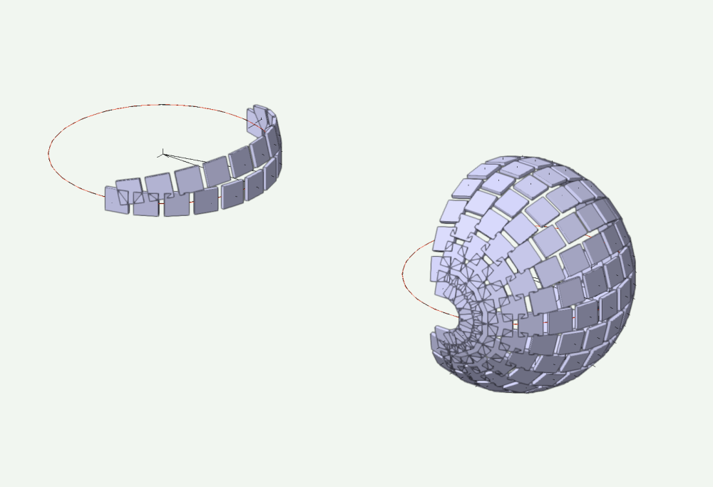
Yet another thought. I can imagine another approach, but didn't try it yet, maybe not possible in vwx (See @Jeff Prince above): A basket ball, a handful of Scrabble™ tiles. Hot glue. Mark off a 1/4 or 1/8 area of the ball. Heat up the glue gun . . . Stick a course of tiles across the marked off area. Follow a great circle so that they have desired gap and adjacent edges are parallel. Stick another course on either side of the 1st course. Center these tiles on the gaps of the 1st course, but only a little gap between courses Repeat for more courses as desired. Leave blank spaces per the OP design. This scheme could not cover entire surface because overlaps. But would possibly work in the limited area without much deviation. Accept the deviation and move ahead. The 1st course is great circle, but subsequent courses are laid neither on great circle, nor parallels. Each is a unique track. Possibly not even circular? In Vectorworks this might mean moving and rotating all the subsequent tiles by "hand". I will give it a try if I have a moment. -B -
3d-Symbol distribution on a sphere object
Benson Shaw replied to bjoerka's topic in General Discussion
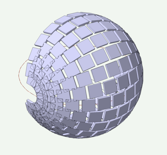
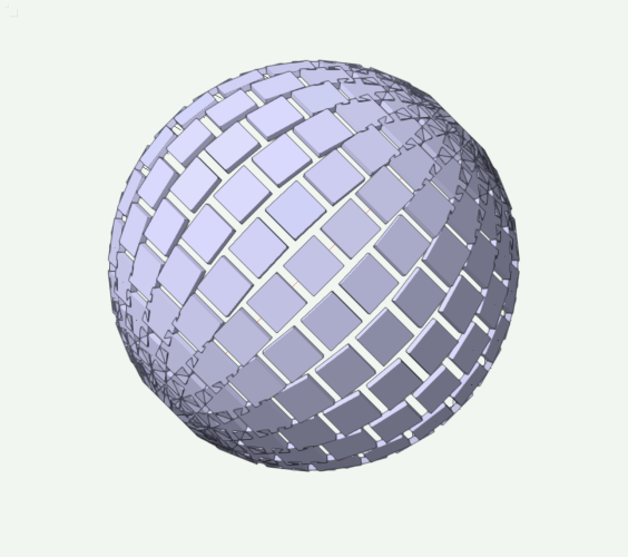
@ all - I think two problems here: 1. The orig may be fudged a bit from the uniform tiling, if that's even expected. See critique. But, no matter. . . 2. I think the tiles are laid out on great circles, rather than latitudes. This allows even space and parallel edges along each course, rather than leaning in towards the pole, causing a tapered gap. In a great circle arrangement, the courses have tapering separation (ie meeting at the poles). Tiles will overlap near the "poles", but overlaps can be deleted, leaving enough tiles to occupy required portion of a "sphere". If the tiles are small/numerous, compared to the sphere radius, the widest part of the taper (between courses) can be somewhat small. Easier for me to cover most of the ball, then rotate whole array to make the courses on angle. My tiles are pretty big, only 24 facets around the great circle. 40 or 50 facets would be closer to the orig example and allow more tiles/surface without overlaps. Also, I approached this with poles on the layer plane. Second course is dupe of 1st, rotated around layer plane to align tile and gap center, then rotated about my (layer plane) polar axis. Easier for me to think about it that way. Similar process could establish polar axis perpendicular to the layer plane. -B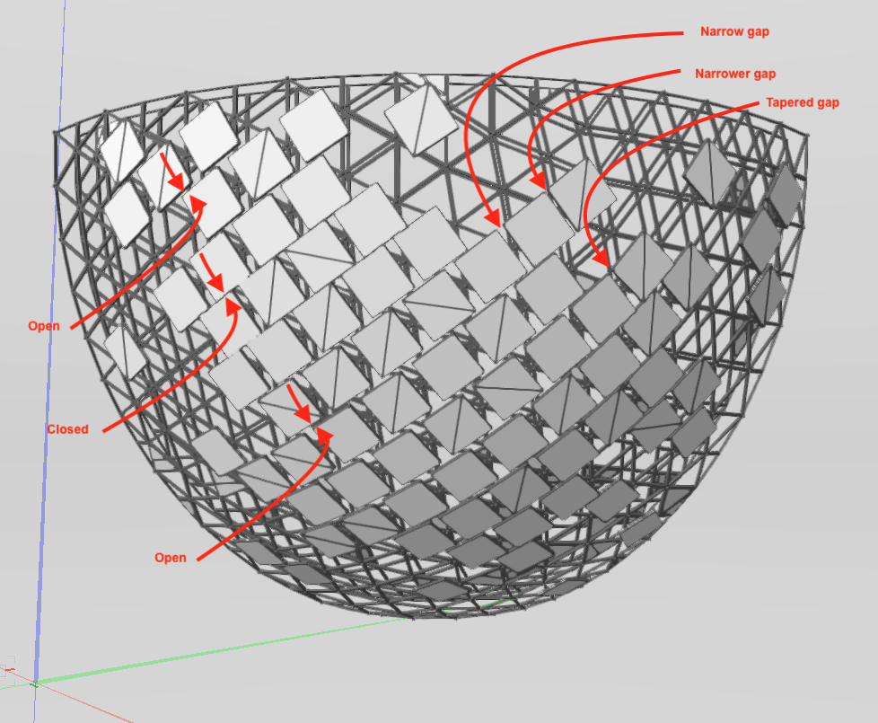
-
Solid subtraction of multiple separate objects
Benson Shaw replied to serge_01's topic in Solids Modeling
Another thought if the "line" of extrudes to skewer on a rod fits the need. Only works if pairs of extrudes have a straight edge facing the gap between. Splitting edge doesn't need to be parallel to axis of the "rod". Make a solid addition of the extrudes (now they act as a single object) Place the "rod" as needed. Subtract Solids (extrudes have holes but are a single Generic Solid) Use the split tool (120 times, ugh! Sorry). Tool has to drag an edge of each extrude, eg in Top view. Here's a little video. -B Screen Recording 2023-09-25 at 10.44.52 PM(1).mov -
Solid subtraction of multiple separate objects
Benson Shaw replied to serge_01's topic in Solids Modeling
Need more info. Can you show a sketch, screenshot, or sample file? Or at least a more detailed description? eg a line of extrudes (different sizes). Make a hole through the lot of them so that a "rod" fits through. -B -
Can data tag reference and do math with its own fields?
Benson Shaw replied to Benson Shaw's topic in Data Tags
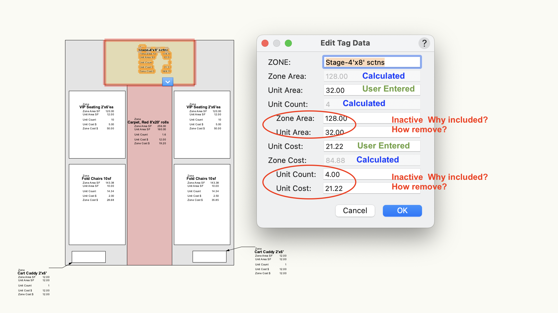
OK, still testing. Note - not trying to invent an event planning workflow. It's just a way to test data tag function. File has a new record format with a field for each kind of entry in the Data Tag, and a new Tag with fields corresponding to the record format fields. Works fine if user entry made via the Edit Tag Data dialog. OIP Data tab updates appropriately. But changes made in the OIP Data tab can mess up the Data Tag calc and entry fields. And no good way to back out of that error. Also, the Edit Data Tag dialog shows some extra fields which report calc results and current user entry data, but are inactive. Kinda confusing. any comment welcome. -B Tag:Record test.vwx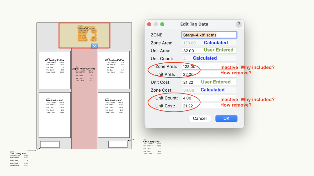
-
@MGuilfoile Can you put those curves and your loft in a file and post it so we can test? Otherwise, can't really comment on the Shell limits. -B
-
Glad it’s working. I think you mean the red highlighting when you say “selection”, but just in case . . . Note that the loft operations do not require prior selection (Select Tool) of the various NURBS Curves. They will highlight when clicked if eligible, whether selected or not. Verify on your Windows CPU that Vwx prefs for interactive display settings for highlighting and pre selection are as expected. Might have something shut off there. -B
-
Can data tag reference and do math with its own fields?
Benson Shaw replied to Benson Shaw's topic in Data Tags
@Tom W. Wow, many thanks for that! I'm trying to learn more about Data Tags. Use of single record format applied to many objects, then same data tag with user input for the variables is great. Also good demo using the destination data area. Excellent! -B -
I’m pretty sure the logo used to link to the vwx home page. Wonder why the change. I noticed first time a few months ago. -B
-
@MGuilfoile did you convert your arcs to NURBS Curves? 2d Arcs will not loft, nor will 3d polyline “arcs”. Try this: Select the 3 arcs, then Modify menu>Convert>Convert to NURBS. Result is a group containing 3 NURBS Curves. They should look the same as the unconverted objects, and like the tutorial objects. Ungroup. Or, if you already did the conversion, Make sure that the original objects are not still there, coincident with the NURBS. Delete or move them. Now try your Loft process. If you are in the Loft Birail Sweep mode of the Loft tool (what you described), the NURBS Curves should highlight as shown in the tutorial. Post back and attach your file if things not working. Lofting is really wonderful. Keep trying and post here as needed. -B
-
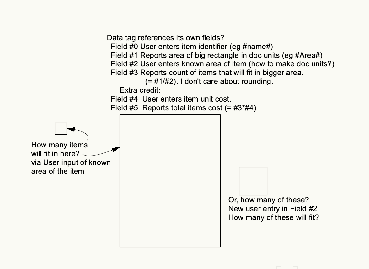
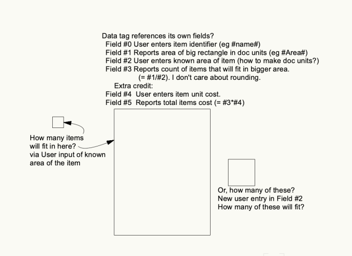
With only limited experience, trying to bend a data tag to my will. Goal is to multiply or divide value in a calculated field by the value in a User Entered field elsewhere in the same data tag. Associated objects are just basic polygons with no record formats. Is this possible? The "items" in attached image do not need to be present in the drawing. I just input an area value of my choice in Field #2 of the Data Tag. Any comment welcome. -B
-
I think that post was Peter Cipes sharing his tip to place a rectangle/polygon with white fill covering the viewport. Set the opacity of the poly as desired. A stack of two or more VPs with interposed polygon(s) can emphasize items shown in the the top VPs. i suppose the transparent poly could instead be placed in the VP annotations, maybe with callouts, dims, etc on top of the poly if they need clarity. Snapping might be a pain. -B
-
The Blessing* - problem with retaining wall site modifier
Benson Shaw replied to IanH's topic in Site Design
@m deasy Are there other site mods overlapping/touching the retaining wall mod? That causes conflict which usually shows up as warning triangles in Top/Plan. One trick is to create a sacrificial duplicate wall but assign it smaller wall thickness. Create new retainer then delet the wall. Retainer will be slightly embedded in the original wall volume, but should avoid conflict with other mods. or Can you edit the retainer and drag the end points up to desired z? or Just a thought - did you try delete the retaining modifier, then regenerate the retaining modifier from the (new?) wall? Might be the parameter for that low edge defaults to z=0, so needs adjustment during creation. ??? -B -
@StefanoT thanks for showing the completed campus and design images. Superb! -B
-
HARDSCAPE - PATHWAYS - JOINT PATTERN CURVED PATH
Benson Shaw replied to Stu Wilson's topic in General Discussion
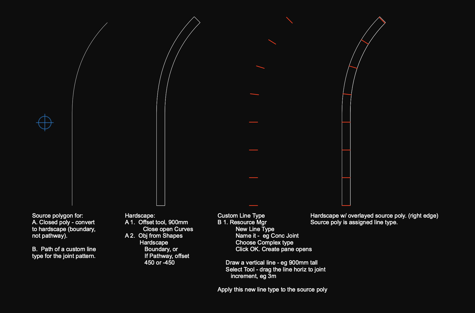
@Stu Wilson Guessing - Looks like you drew the entire border as a 2d poly, then created hardscape from this source, then assigned the hardscape as a pathway type. If this is your workflow, then the joints might extend as shown. I have little patience for such parametric mysteries and prefer to use direct modeling or other work flows. For this joint pattern, with constant hardscape width, I suggest create a custom line type. Create the hardscape shape by drawing then offsetting one of the edges (save the source poly), then create a new line type, then apply the line type to the source poly. Example shows simple score lines across the hardscape. Line type can instead make other, smaller paver shapes by drawing rectangles (or hex, square, etc) in the line type creation pane. Smaller pavers will need a new source line for each course. Use the Offset tool to "duplicate" the source poly for each new course (disable the Close Open Curves option). Post if more detail needed. -B
- 1 reply
-
- 2
-

-
@Rishie If I'm understanding your method, your decomposed "VP" is no longer an actual VP, but rather a bunch of geometry in a group. That includes the geometry from the crop object (a rectangle?). Enter the group, select and delete the "crop object". If you subsequently edit the orig VP and need another decomposed copy for referencing, uncheck the Show Crop prior to decomposing (should prevent the crop from appearing in the group). Or, if the crop is visible in the newly created group, edit the group and delete the rectangle. HTH -B
-
Site Modifier issue with proposed and existing contours
Benson Shaw replied to Erikah's question in Troubleshooting
Oh yeah, forgot to mention - in that second idea, do not place any modified contours in the Site class. Delete those modified contours which were added to the Site Class in your 1st tests , or at least remove them from the Site class. Also the 3d polys pasted into the site model Edit Proposed Contours screen should NOT be placed in the Site class. Class them as you would normally class your contours. -B -
Site Modifier issue with proposed and existing contours
Benson Shaw replied to Erikah's question in Troubleshooting
You almost have it. Couple comments: I think the contours added in the Site . . . Class are acting as expected. They are connecting to nearest points around them. A grade limits object around the whole site might help, but you have a better option at hand in your second site model (DTM#2) . . . Copy the set of contours used to form your successful DTM#2 select your DTM #1 and in OIP click the option to Edit the Proposed Contours. in the edit pane, select all and delete everything Paste in Place your contours from DTM#2 exit the edit and update the DTM verify by switching to/from existing view and proposed. post back as needed -B -
Data Tag Sequence Renumber Patterns
Benson Shaw posted a question in Wishlist - Feature and Content Requests
1. The available data tag sequence patterns are all zig zag. No good choices are available if preferred pattern is "around", eg window or door tags along series of walls. Wish: Add Clockwise/Anticlockwise options. 2. Access to the sequence pattern dialog is deep nested. Wish: A friendlier workflow would result from shallower nest, eg combined functions in one or several of these dialogs. 3. Renumber dialog indicates pattern will apply to " . . . all tags of this type . . ." Is Data tag "type" a defined concept? Perhaps "style" is meant here? Wish: Rewrite to clarify intended result. -B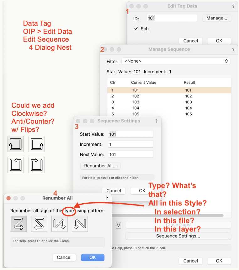
-
A way to make a variable Extrude - ¿ Use a PIO ?
Benson Shaw replied to Elite Exhibits's topic in Solids Modeling
@lineweight nice window detail! Correct me if I’m wrong, But, that return panel join, sloping down from the corner will never make a “matched“ joint as a two piece miter or butt joint using the same profile to change planes AND turn. Some transition segment or reshaping (shave the top? Squish parts? Lotsa caulk?) or coping is required. Try it with a couple extrudes in Vectorworks, or by sawing a couple pieces of wood molding. The wall tool cannot resolve it because the real world geometry does not conform in a two piece joint. One could make it with 3 pieces - the mitered turn (short segment of wall) then miter the slope into the short bit similar to bannister joinery. -B -
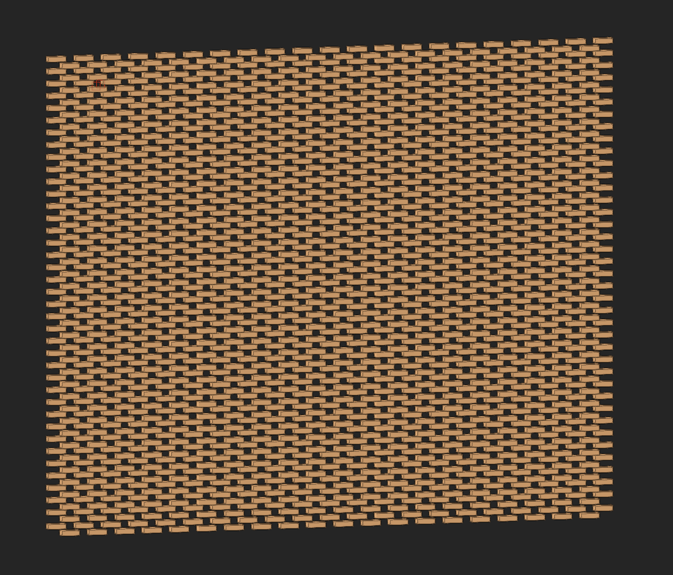
Probably a texture would do the trick. But if you want to model it, I suggest make a brick symbol (2 or 3 of them with varying color). Duplicate Along Path (or Move By Points) horizontally for the 1st course. Fixed distance to accommodate the blank spaces. Make a symbol of this. Then dupe the 1st course symbol and modify for the next course up with end offsets. Then dupe the two symbol courses vertically via Move by Points to complete the facade. If needed, after the whole facade is formed, ungroup a few courses and replace a few brick with the alternate colored symbols. Pain, I know but goes fast once you get the hang of it. Hopefully others will have better ideas. -B

-
Fillet a polyline doesn't cooperate
Benson Shaw replied to MartinBlomberg's question in Troubleshooting
The container/perimeter object OIP can show Closed even when the internal polys are not closed. Apply that Cmd[ shortcut to access/edit the internals. -B -
Fillet a polyline doesn't cooperate
Benson Shaw replied to MartinBlomberg's question in Troubleshooting
The fillet tool has a VERY small value (13) in this file. It is filleting, but not discernible except at huge zoom where the graphics are, um, confusing. And, one of the internal polylines is not closed. That open corner does not fillet, until closed. HTH -B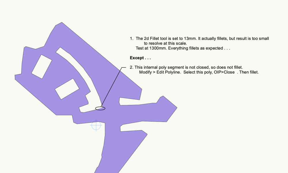
-
Cutting Complex Patterns Into Solids
Benson Shaw replied to Chame_liam's topic in General Discussion
Forgot to mention some potential cutting issues. Check with the cutting personnel for tips and limitations: The 2D layout is best if the drops are individual polys arranged on the sheet outline - whether whole sheet or the 6 facets. Rather than the clipped poly used for the extrude. Some cutters software interprets only straight segments and circular arcs. Beziers or splines may not be recognized or may be “exploded” into a few or many straight segments. Get a proof prior to the cut. -B